 |
CTM Racing Heavy Duty Rebuildable U-joints By Bill "BillaVista" Ansell |
IntroductionEvery once in a while there comes along a product so "in a class of its own" that it literally defines the genre. Such products set the standard by which all others are judged. CTM U-joints are just such a rare beast. They've been available for several years now and remain the first and only choice in extreme duty U-joints. |
 |
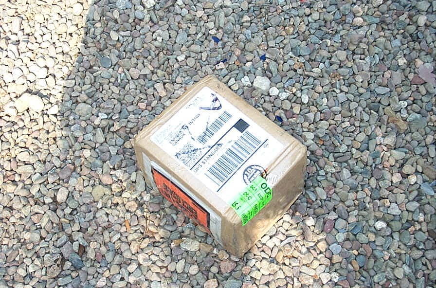 |
When you decide you want the best U-joint money can buy - and order your own CTMs - this is what comes to the door. | |
 |
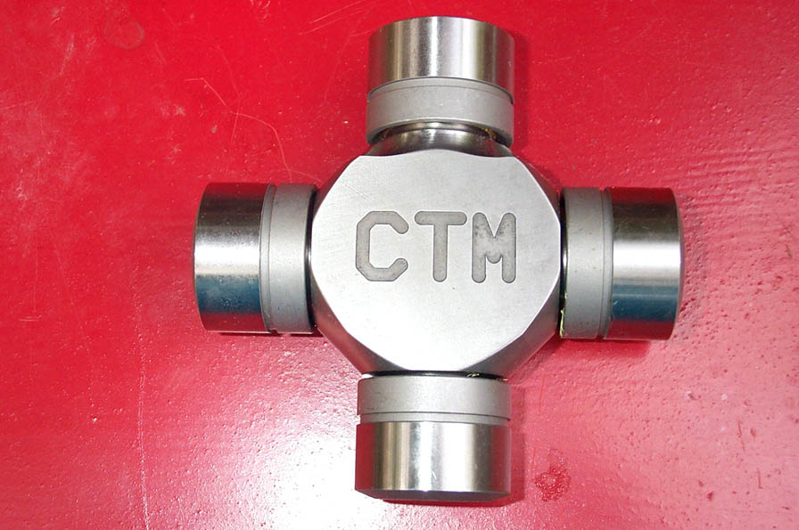
The Dana 60 U-joints (part #C160-3750) from CTM Racing Products replace the OEM stock part #5-332x | |
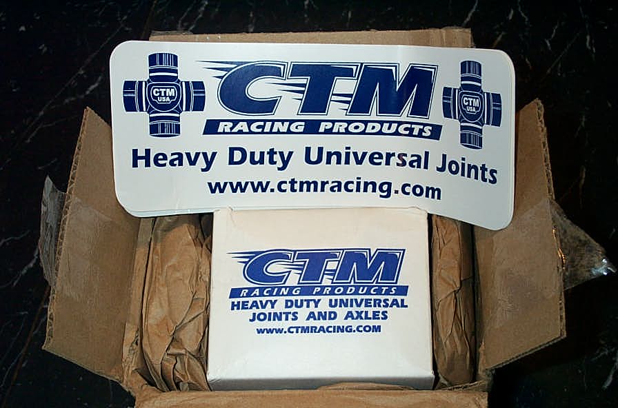 |
You get cool stickers to show-off your ultimate U-joints. | |
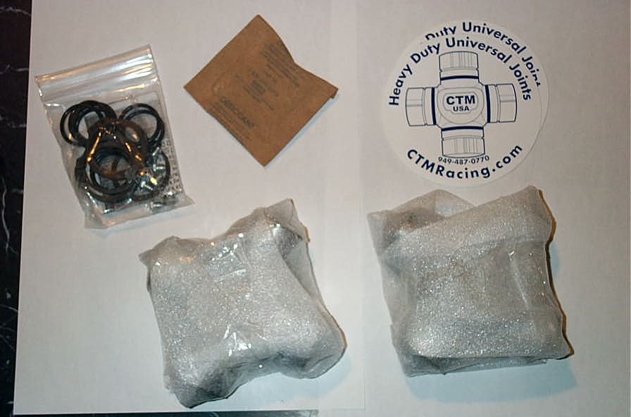 |
And inside the box there are 2 complete joints, a hardware kit, a couple more stickers, and a small packet of desiccant to keep it all dry. Remember not to get too excited and eat the desiccant - it warns you not to on the packet! |
|
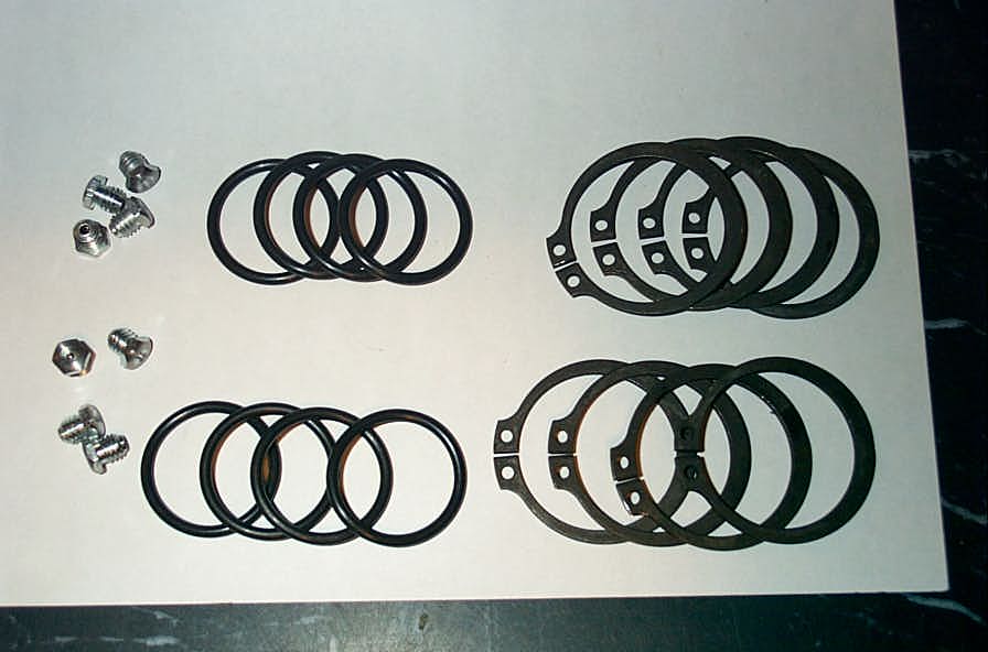 |
Inside the hardware kit there are 8 flush grease fittings, 8 O-rings, and 8 full-circle snaprings. | |
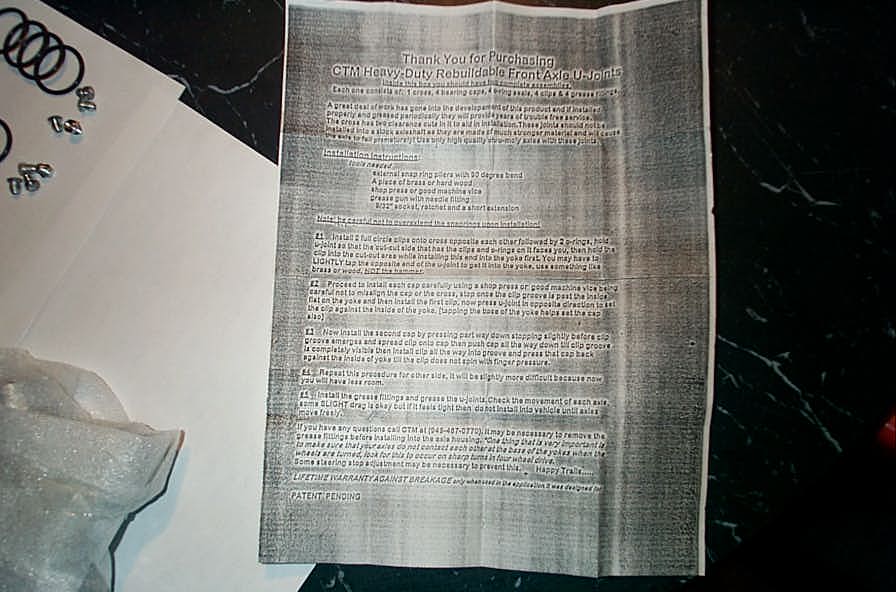 |
There's also a fairly detailed instruction sheet - well copied. I have reproduced the instruction sheet below, letter for letter, should you wish to read it or save it electronically. I also detail the installation process below with over 30 detailed photos, and have also compiled that section of this article into a printable PDF document that you can save, print, and take to the shop if you like. |
|
|
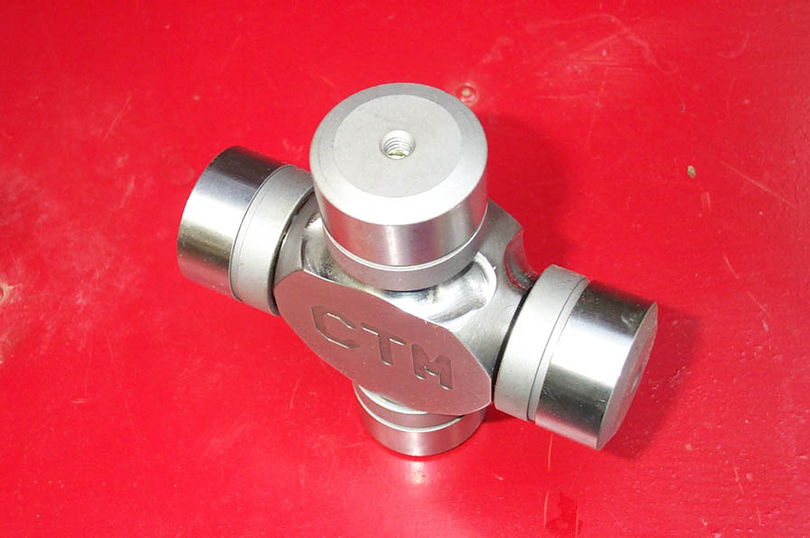
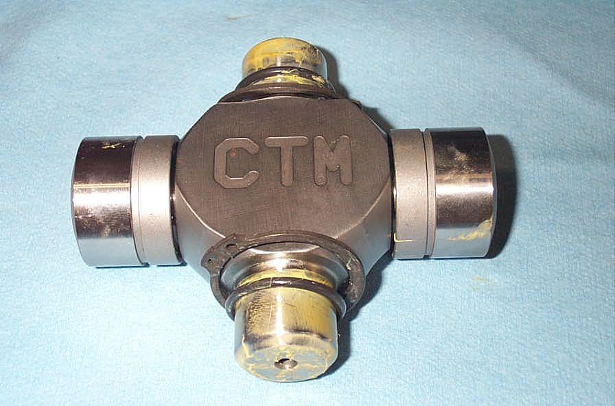
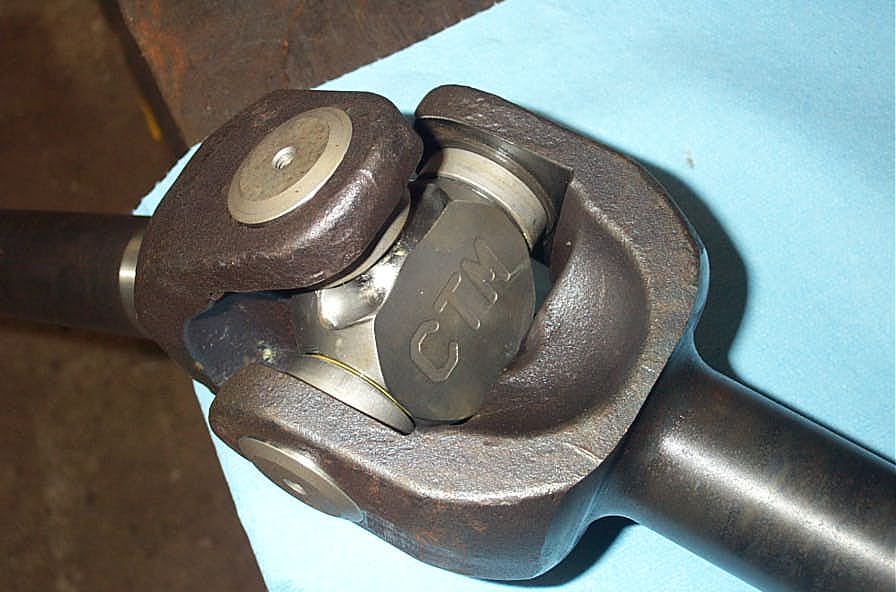
The joints themselves are works of art. I took a bunch of photos - and have tried to do them justice, but they really need to be held in your hands to get a full appreciation of the product. They are forged from 300m Chrom-Moly steel, heat treated, machined, and cryogenically treated for the strongest possible assembly. All the tricks are used with no expense spared or shortcuts taken. |
|
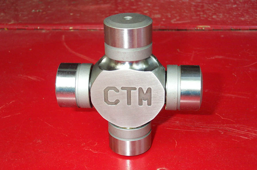 |
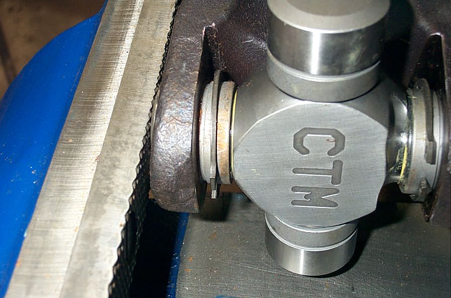
Here you can clearly see one of the two clearance cut-outs needed for installation. The reason for them will be made very clear in the installation section below. | |
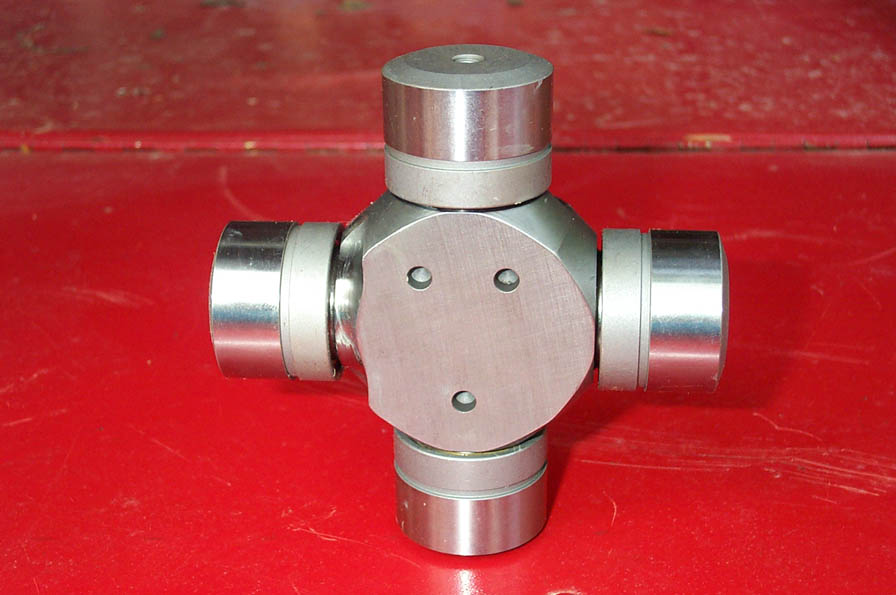 |
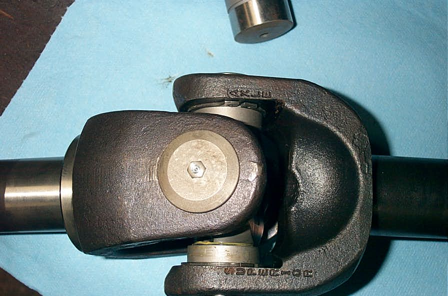
On the back of the joint are 3 small circular impressions that serve no function, but are remnants of the manufacturing process. | |
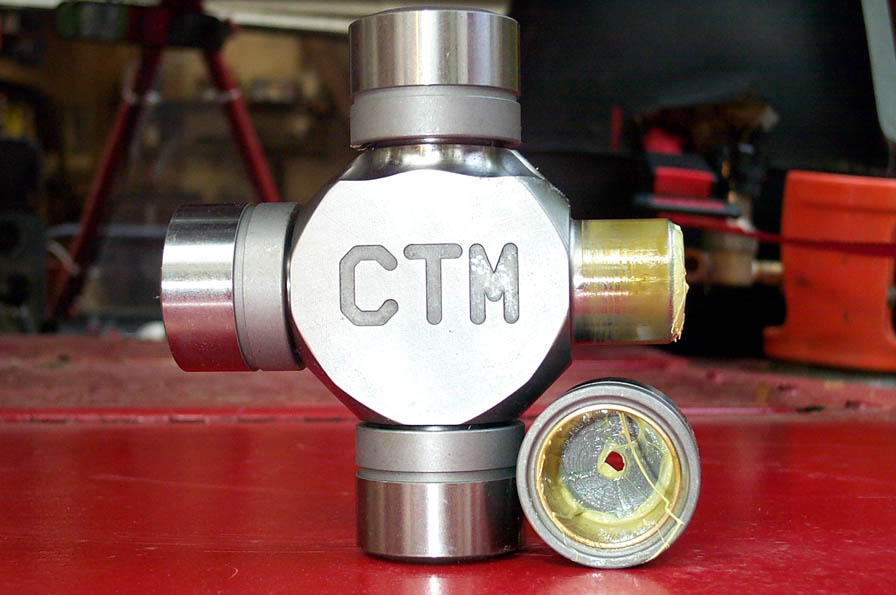 |
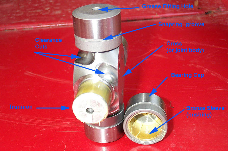
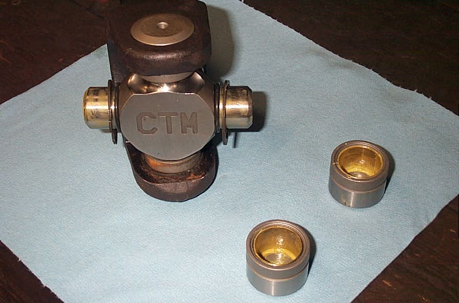
One of the keys to the CTMs brute strength is the elimination of needle bearings between the trunnion and bearing cap. This allows greater size and strength in the trunnion itself, as well as removing the weak, troublesome needle bearings themselves. Needle bearings are fine for the longevity requirements of multi-million mile highway fleets - but they are not up to the brutal abuse of hard 4x4 use - they gall, distort, and ultimately disintegrate rather easily. | |
 |
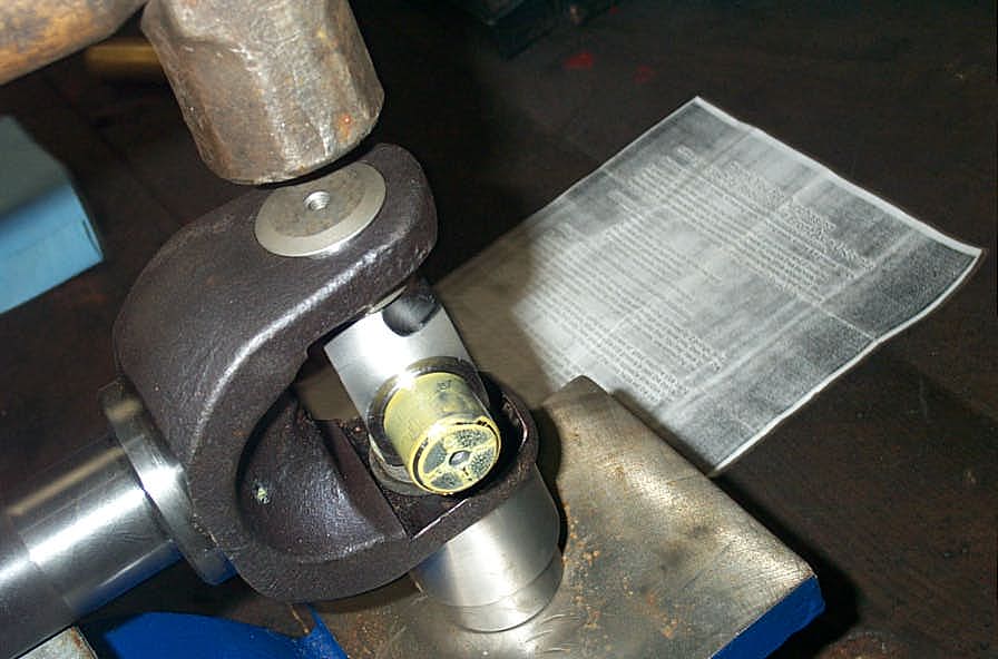
CTM U-Joints use a bronze sleeve (visible inside the bearing cap) in place of needle bearings. When kept properly greased they have proven to show little or no wear. Axle Jack at CTM racing says "Keep these sleeves well greased using a needle adapter on your grease gun and abuse them worry free." |
|
 |
How often they need to be greased will depend on the environment. In the harshest of climates or conditions (water, sand, mud etc) it is best to grease them after every run. This will purge any water or gunk from the joint and ensure it remains properly lubricated and corrosion free. CTM has customers that have over 10,000 miles of street and trail driving on their U-joints without any sign of wear. |
|
 |
CTM Racing U-Joints carry a "LIFETIME WARRANTY AGAINST BREAKAGE" when they are installed, and maintained properly in the application for which they were intended. | |
 |
The U-joints are also, should you require it, fully rebuildable. Bearing caps, bronze sleeves, O-rings, snap-rings, and grease fittings are all individually replaceable. | |
 |
Finally, I should mention that CTM U-joints are designed for, and should ONLY, be used with high quality alloy axles that have the yokes hardened. To do otherwise will cause premature shaft failure as the extremely hard and tough CTM U-joint will cause the relatively soft "ears" on the yokes to oval out, resulting in loose caps and assembly failure. this means you cannot run CTM U-joints in Spicer or Moser axle shafts. |
|
Here is a word for word transcript of the official CTM instructions:
Superior Alloy axle and CTM U-joint Assembly (for a printable PDF version of the installation - click HERE) |
||
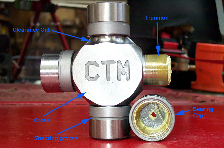 |
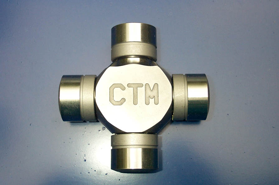
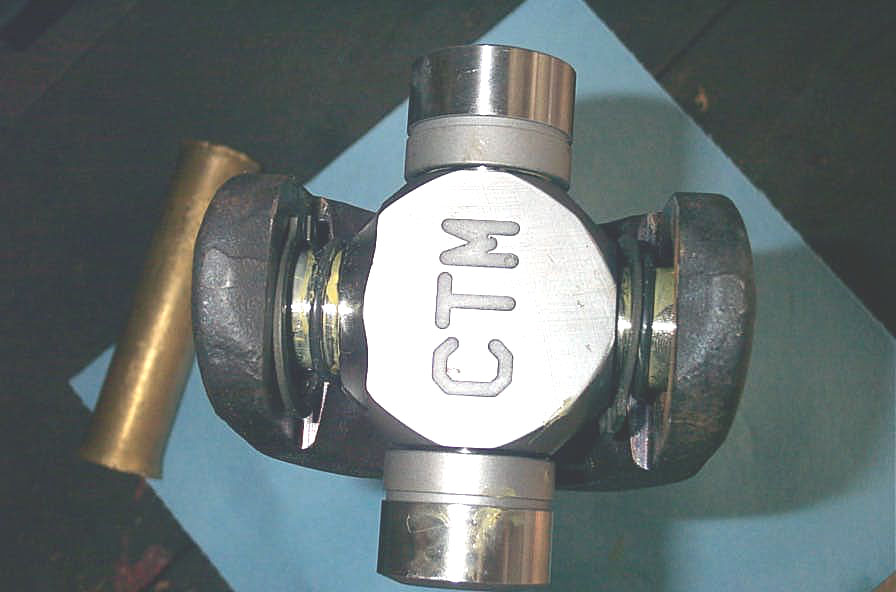
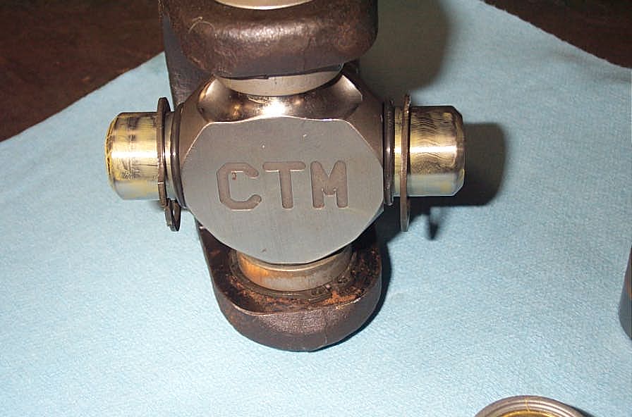
Naming Conventions For clarity I have illustrated the names I shall use for the parts of the CTM U-joint and kit in the following pics to the left. Here is a front view of the joint... |
|
 |
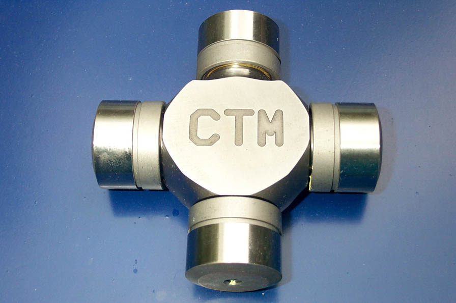
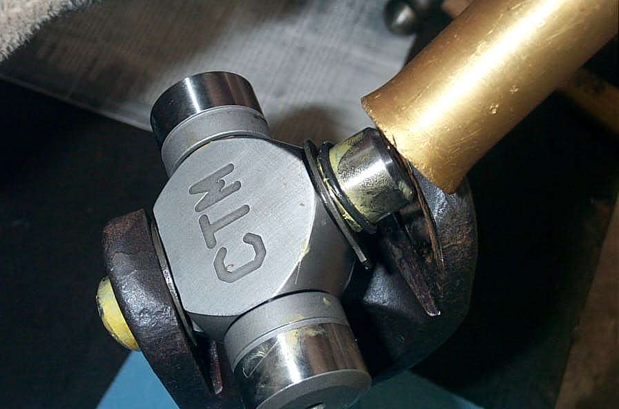
...a side view of the joint. The main body I will call the "cross", the bearing journals "trunnion", and the bearing caps "caps". |
|
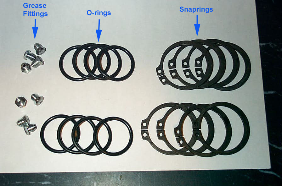 |
The supplied hardware kit. Simple stuff, sure enough, but by now you know I'm a fanatic for clarity and accuracy. |
|
 |
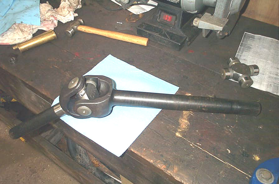
In the "tools needed" section of the official instructions with the CTMs say "shop press or good machine vice." I had a piece of junk bolted to the bench where a vice should go, so I took this opportunity to rationalize the purchase of a nice new vice. Hey - when Axle Jack says get a good vice...you get a good vice! You'll want one with jaws that open at least " |
|
 |
1. Take a joint, remove a pair of opposing bearing caps, and onto each trunnion place a snapring followed by an O-ring. | |
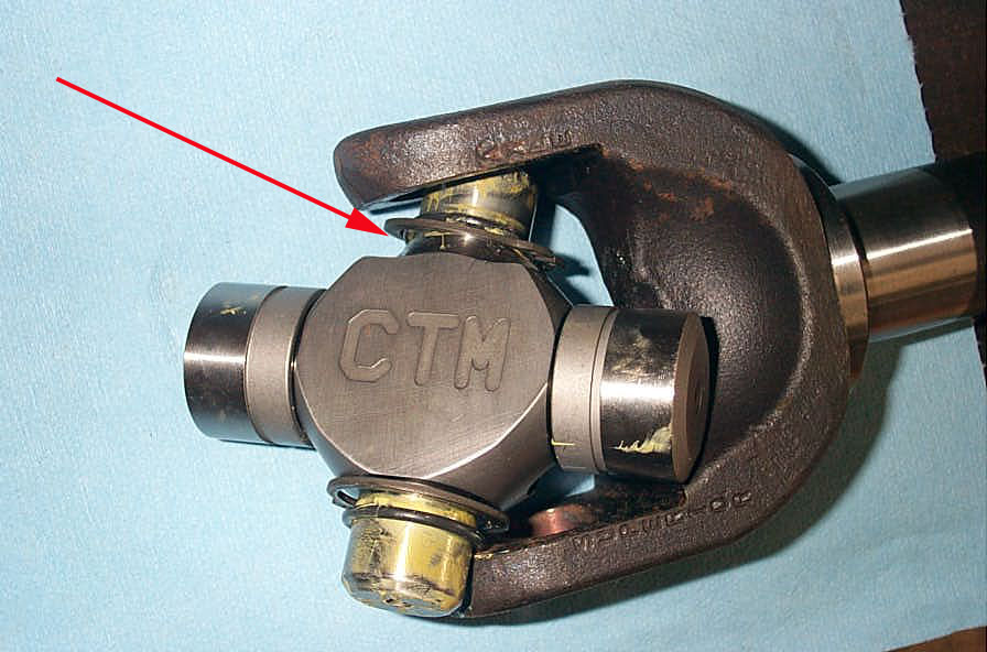 |
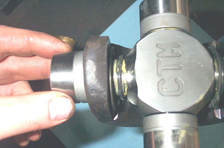
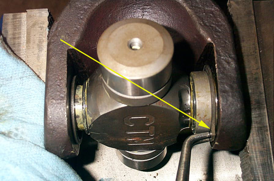
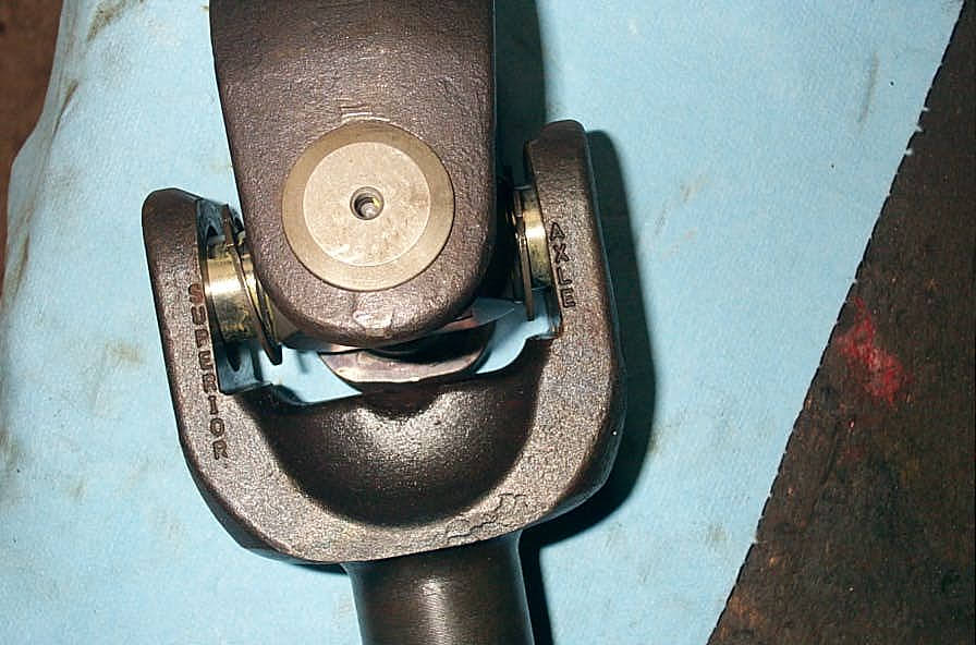
2. Hold the cross so the CTM label faces you and the cut-out is at the top facing you. Place the snapring in the cut out area (red arrow) and slip this trunnion into the yoke first. | |
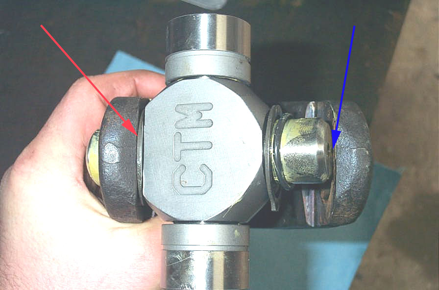 |
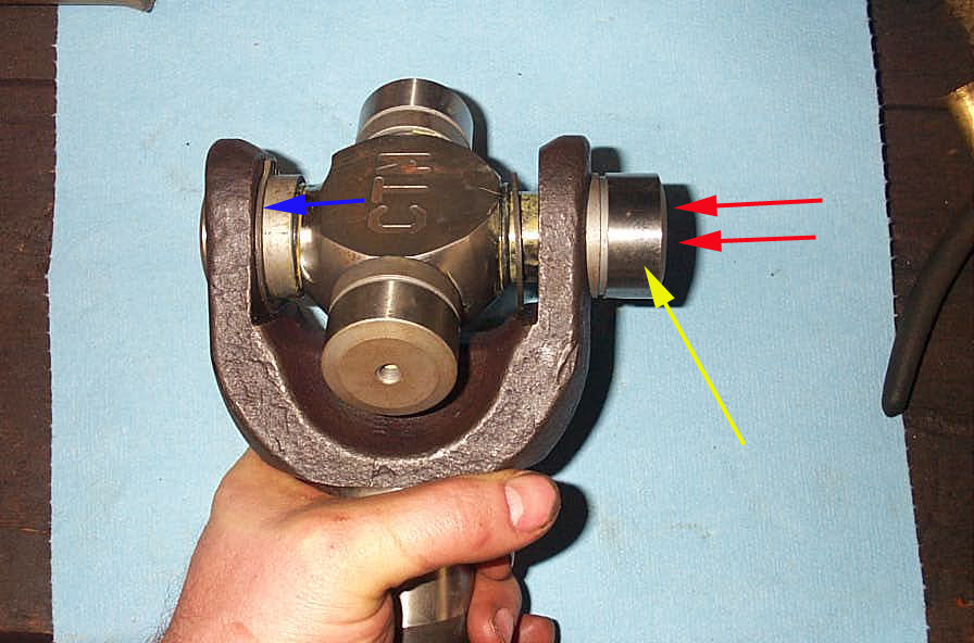
3. Even with the snapring in the cutout (red arrow) clearance at the opposite trunnion will be very tight (blue arrow). | |
 |
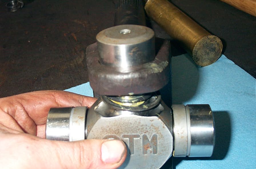
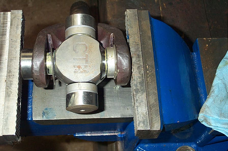
4. Use a brass or hardwood drift to GENTLY tap the trunnion past the yoke... | |
 |
... until the U-joint sits fully in the axle yoke. | |
 |
5. Carefully install a bearing cap on the trunnion by pressing it through the hole in the axle yoke. | |
 |
Start by using your fingers, being extra careful to keep he trunnions, caps, and yoke bores all lined up, and making sure the O-rings and snaprings aren't pinched or caught up... | |
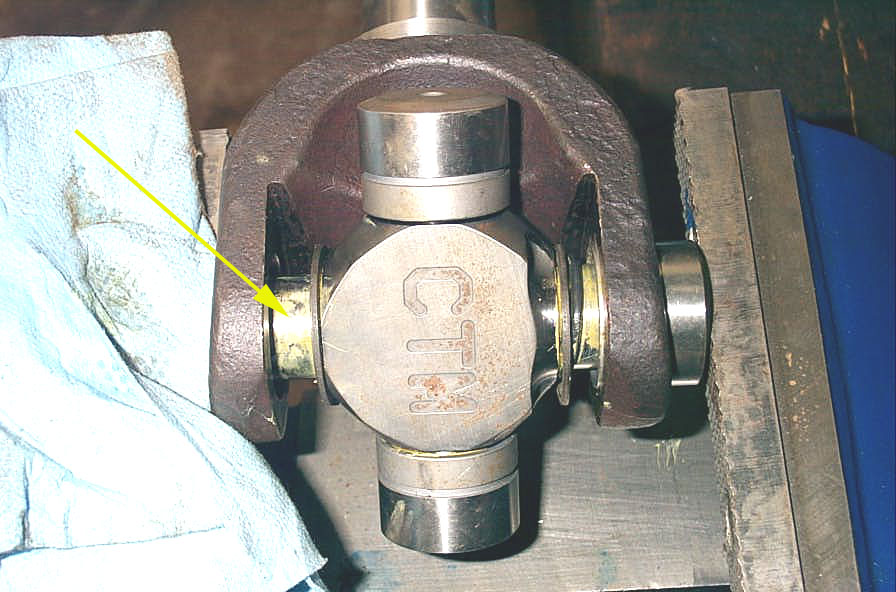 |
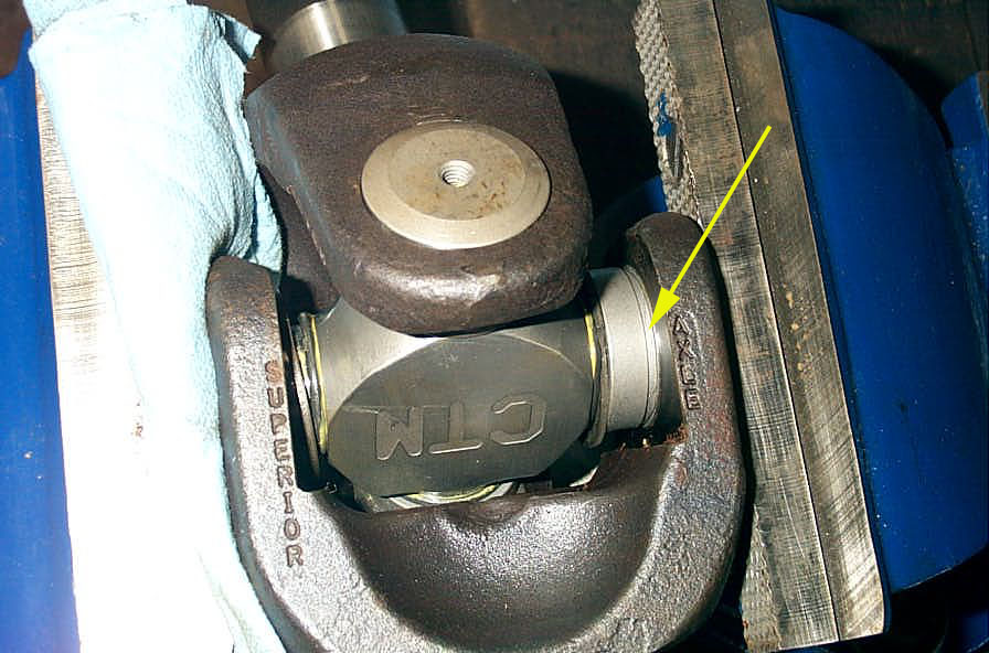
6. Once the cap is lined up and finger tight proceed to press it in using your vice or shop press. When doing the first one, be sure to use a rag to protect the end of the opposite trunnion (yellow arrow) from being marred by the jaws of the vice. | |
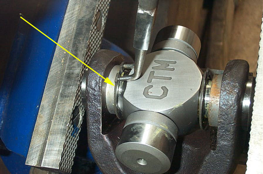 |
7. Pause partway once the cap protrudes past the inside flat of the yoke. Spread the snapring with pliers and slip it over the cap (yellow arrow). | |
 |
8. Continue to press the cap on until the snapring groove (yellow arrow) is fully inside the yoke. | |
 |
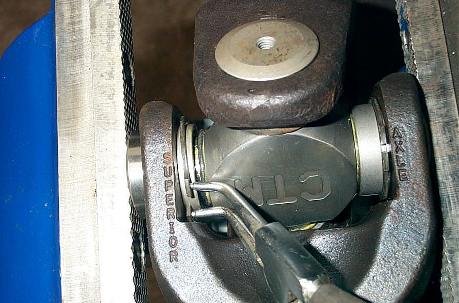
9. Install snapring in snapring groove using snapring pliers (yellow arrow) (snapring, snapring, snapring.....hmm, funny - after you say it to yourself 36 times the word loses all meaning!) |
|
 |
10. Place the other cap on its trunnion (yellow arrow) and using the brass or hardwood drift tap the joint in the direction indicted by the red arrows to seat the snapring (blue arrow) tightly between the flat on the inside of the yoke and the snapring groove in the cap. Set the cap and snapring in this manner so that you cannot spin the snapring in its groove with finger pressure. | |
 |
11. Continue pressing the second cap on with your vice or press and continue as per the first cap install. | |
 |
12. Remember to pause and slip the snapring over the cap, press cap until snapring groove is visible inside yoke, and insert snapring in groove. | |
 |
13. You must also press joint back in opposite direction to seat cap and snapring. I found it necessary to place cap over a large socket and tap the opposite cap to seat the snapring. | |
 |
When you have finished installing both snaprings and clips, the cross should rotate freely in the bearing caps with no hint of bind, but you shouldn't be able to spin either snapring in its groove just by trying to turn them with your fingers. | |
 |
14. Continue by removing the cpas from the remaining 2 trunnions, and installing an O-ring followed by snapring onto both. | |
 |
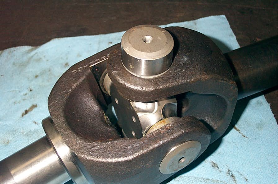
15. The trickiest part of the CTM installation is getting the cross in the second yoke. Because of the size of both the U-joints and the Superior Alloy shafts clearances are quite tight. You will have to carefully align the trunnions with the yoke bores... | |
 |
...and make use of the second clearance cut-out (yellow arrow)... | |
 |
...too get the trunnions to pop through the bores. But it will fit, just be patient, and don;t hammer or force anything but feel free to apply a little persuasion with a brass drift. Not only is this trickiness more than made up for by the fact that there are NO needle bearings do drop, crush, get trapped etc - but if you're struggling, remember that the parts fit tightly because of their maximum size and strength - which is exactly what you want! |
|
 |
16. Once the cross is situated in the yoke of the second axle, proceed as above to press on the first cap. | |
|
17. Stop when the snapring groove is inside the yoke Don't forget to frequently pause and admire the amazing beef of your super-cool new axles and U-joints ;-) |
|
 |
18. Install the snapring. | |
 |
19. Install the final cap. | |
 |
20. Final snapring in place. | |
 |
AWESOME! Very cool, VERY beefy, - form and function in one sweet package. installing the CTM's was a JOY! I have never had such an easy time installing U-joints. I didn't have to force anything, no dropped needles, no getting the whole thing assembled and one cap wont sit right and you realize a needle has fallen over and you have trapped it - jeez I hated that! I love these joints. Down with needle bearings I say! |
|
 |
21. Install the grease fittings in the ends of each of the caps and grease the U-joint at each cap with a high quality synthetic grease. | |
 |
22. Before installing the axle assemblies into the axle housing - do a final check that all yokes move smoothly and freely with no binding; that all caps are greased and grease fittings are installed; and that all snaprings are firmly seated in the groove and do not spin under finger pressure. | |
InstallationMy intent was never to make this article a detailed installation article - I'm assuming that we're pretty comfortable with axle R&R at this stage. However, should you wish to review or study detailed information regarding the building of a D60 front axle, that information is readily available in several articles I have written. You can check out: The original Spicer D60 front axle maintenance manual The one ton axle tech manual compiled from US military manuals The Dana light axle service manual (torque and setup specs) and my other tech articles: Dana 60 front axle kingpin rebuild That said, here are a few pics of the Superior/CTM assemblies being installed in the BV-60. |
||
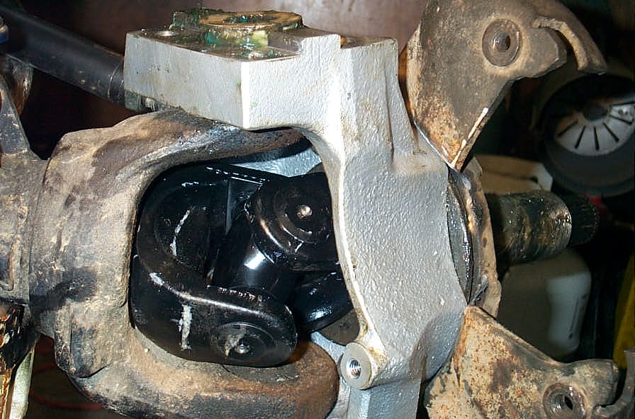 |
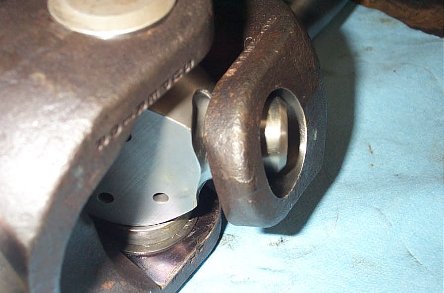
It is critical that you carefully check clearances once everything is installed. The knuckle must be cycled from lock to lock while the axle is being rotated (a helper is enormously useful here) while you carefully check to make sure that the axle/U-joint assembly doesn't contact any part of the knuckle or axle housing at any time. |
|
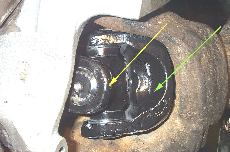 |
And also check to make sure that there is no contact possible between the top of the yoke ears (yellow arrow) and the bottom of the yoke on the opposite shaft (green arrow). If there is any interference, you will be able to see, hear, and feel it, and you must adjust your steering stops to eliminate it. It is wise to allow a little extra clearance to make sure nothing contacts under hard use where things may compress a bit. |
|
FAQQ: How often do they need grease?A: Good question, that all depends on driving conditions and whether or not the U-joints were subjected to water or mud. Generally, grease them every trip or when you lube the rest of the vehicle once again depending on driving conditions. (The harsher the conditions, the more often you should grease them) Q: How long will they last?A: That all depends on how frequently you grease them. It's kind of like changing the oil in your engine. If you do it regularly then it will last a very long time. Q: How do you remove the U-joints caps if it becomes necessary for maintenance?A: Method 1 - Remove the grease fitting
from the cap, thread a metric 6x1.0 bolt into the grease fitting hole and use
it to remove the cap |
||
|
Sources: CTM Racing Products, Inc. 32991 Calle Aviador #E |
|