 |
ARB 14-Bolt Air Locker Install By Bill "BillaVista" Ansell |
IntroductionOh mighty 14-Bolt, how do I love thee? Let me count the ways! With apologies to Elizabeth Barrett Browning (1806 - 1861), and in all seriousness: it's no secret how big of a fan I am of the GM 10.5" 14-Bolt full-float rear axle. There are many reasons why - and I needn't repeat them all here - interested readers and the unconvinced can discover the reasons themselves, along with much more information on the 14-Bolt, by checking out the following articles: But...until recently, there was one fairly major drawback to the 14-Bolt: locker selection was far poorer than for other axles. Not so long ago it used to be that you had open carriers, a few weak/unreliable limited-slips, Detroit Lockers, or a home-made welded-up spool. |
 |
||||||||||||||||||||||||||||||||||||||||||
No more!! Early in 2005 renowned off-road manufacturing giant ARB stepped up to the plate for 14-Bolt lovers with the introduction of the 14-Bolt ARB Air Locker. I myself was tire-scrubbing my way through life in noisy ignorance with a home-made spool in the rear - doggedly preaching the gospel of the mighty 14-Bolt to an audience of largely unconvinced Dana axle owners when Tim the Tech Man from ARB USA called me up to ask if I'd be interested in checking out their new air locker for the 14-Bolt. I politely declined, quite happy with the welded gob of rusty steel that was once a differential in my rear axle...NOT! I jumped at the chance, and promised a full article on the holiest of holy selectable lockers. About a hundred hours and over seven hundred pics later - here is the result.
This article assumes that the reader is familiar with 14-Bolt nomenclature and basic 14-Bolt tear-down/assembly. It assumes you are at least familiar with gear terms and the procedure for setting up gears in a 14-Bolt. It details the installation of the ARB assuming you are reusing your ring and pinion gears and bearings (although I would personally recommend installing new bearings with any gear or locker change). If you are not familiar with any of these terms or procedures, or if you are changing gears at the same time and need a more thorough look at setting up gears in a 14-Bolt, please also refer to my: Installing an ARB air locker is not much more complicated than installing any other carrier - the gears are set up in exactly the same way. However, due to the design and nature of the ARB, there are a couple of tricky steps, and a few things that are critical to get right for trouble-free operation. In fact, I am convinced that there are just one or two places during the install procedure where people tend to make mistakes, and that these mistakes are likely responsible for 90% of the issues some people seem to have later on. You can be sure that I will steer you carefully around the pitfalls - and I know where they all are - mostly because I tend to fall in them all! The Bits in the Box |
|||||||||||||||||||||||||||||||||||||||||||
 |
I can unequivocally say, with complete confidence, that the ARB came in the nicest box I have ever seen a 4x4 product in. So what? Well, apart from just looking way cool - it was my first indication of something that I would become very familiar with by the end of my installation and article - ARB are a top-notch, thoroughly professional outfit. Not only are their boxes the best, but their instructions are the finest I have seen, and their customer service is legendary. In fact - during the course of my installation and the preparation for this article, I had numerous technical questions, and I actually received technical help and personal correspondence from the Engineering Supervisor at ARB headquarters in Melbourne, Australia! He was a hell of a nice fella to boot. It's all these little things that can quickly add up to provide you with confidence in a companies products and service. So...let's get the box open and see if the goods live up to the hype! |
||||||||||||||||||||||||||||||||||||||||||||||||||||||||||||||||||||||||||||||||||||||||||||||||||||||||||||||||||||||||||||||||||||||||||||||||||||||||||||||||||||||||||||||||||||||||||||||||||||||||||||||||||||||||||||||||||||||||||||||||||||||||||||||||||||||||||||||||||||||||||||||||||||||||||||||||||||||||||||||||||||||||||||||||||||||||||||||||||||||||||||||||||||||||||||||||||||||||||||||||||||||||||||||||||||
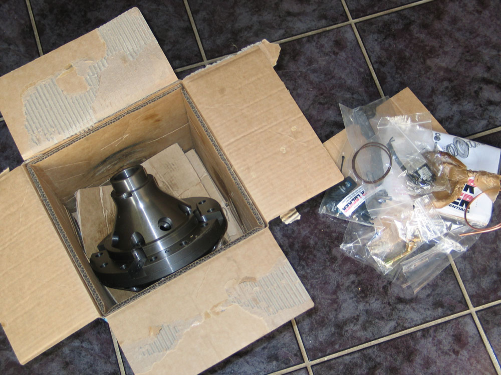 |
Inside the locker was fairly well packaged (it's hard to box up a big heavy unit like this and have it completely secure - short of using a wooden crate). All the miscellaneous parts were well packaged - individually bagged, with critical parts lubricated and wrapped in grease paper to prevent corrosion. Instructions and stickers are included, and the instructions include a clear exploded diagram and parts list so you can easily verify the contents. |
||||||||||||||||||||||||||||||||||||||||||||||||||||||||||||||||||||||||||||||||||||||||||||||||||||||||||||||||||||||||||||||||||||||||||||||||||||||||||||||||||||||||||||||||||||||||||||||||||||||||||||||||||||||||||||||||||||||||||||||||||||||||||||||||||||||||||||||||||||||||||||||||||||||||||||||||||||||||||||||||||||||||||||||||||||||||||||||||||||||||||||||||||||||||||||||||||||||||||||||||||||||||||||||||||||
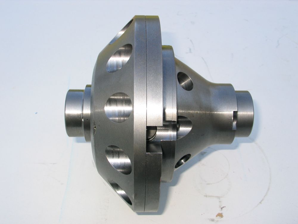 |
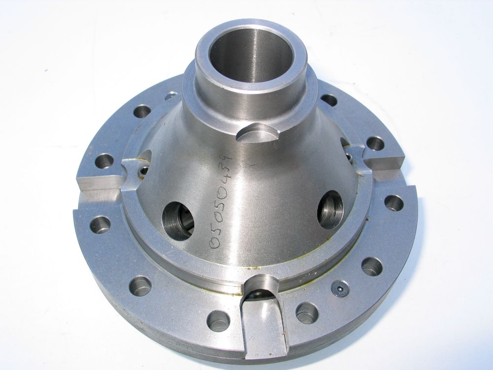
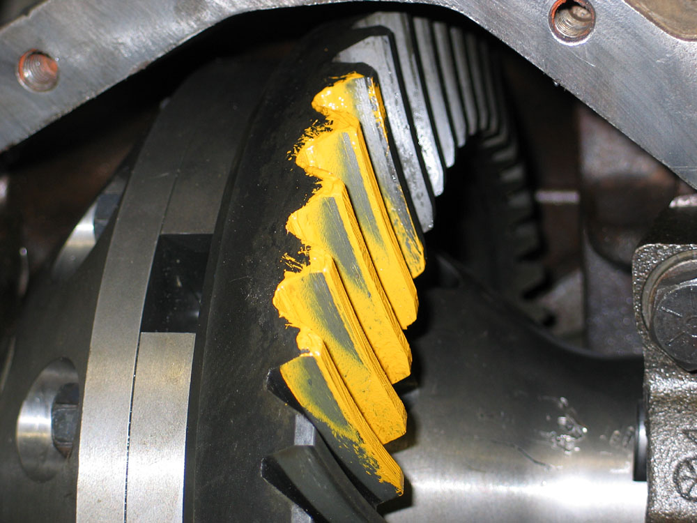
And then there is the beast itself. The next few pictures speak for themselves - there's not much I can add, except that it is even cooler in person than it looks! Note: I have intentionally left the large-size view of the next few pics at full size and resolution so you can get a good appreciation for the quality of the part. |
||||||||||||||||||||||||||||||||||||||||||||||||||||||||||||||||||||||||||||||||||||||||||||||||||||||||||||||||||||||||||||||||||||||||||||||||||||||||||||||||||||||||||||||||||||||||||||||||||||||||||||||||||||||||||||||||||||||||||||||||||||||||||||||||||||||||||||||||||||||||||||||||||||||||||||||||||||||||||||||||||||||||||||||||||||||||||||||||||||||||||||||||||||||||||||||||||||||||||||||||||||||||||||||||||||
|
|||||||||||||||||||||||||||||||||||||||||||||||||||||||||||||||||||||||||||||||||||||||||||||||||||||||||||||||||||||||||||||||||||||||||||||||||||||||||||||||||||||||||||||||||||||||||||||||||||||||||||||||||||||||||||||||||||||||||||||||||||||||||||||||||||||||||||||||||||||||||||||||||||||||||||||||||||||||||||||||||||||||||||||||||||||||||||||||||||||||||||||||||||||||||||||||||||||||||||||||||||||||||||||||||||||
|
The individual serial number, hand-engraved, gives the part the look and feel of a limited edition piece. | ||||||||||||||||||||||||||||||||||||||||||||||||||||||||||||||||||||||||||||||||||||||||||||||||||||||||||||||||||||||||||||||||||||||||||||||||||||||||||||||||||||||||||||||||||||||||||||||||||||||||||||||||||||||||||||||||||||||||||||||||||||||||||||||||||||||||||||||||||||||||||||||||||||||||||||||||||||||||||||||||||||||||||||||||||||||||||||||||||||||||||||||||||||||||||||||||||||||||||||||||||||||||||||||||||||
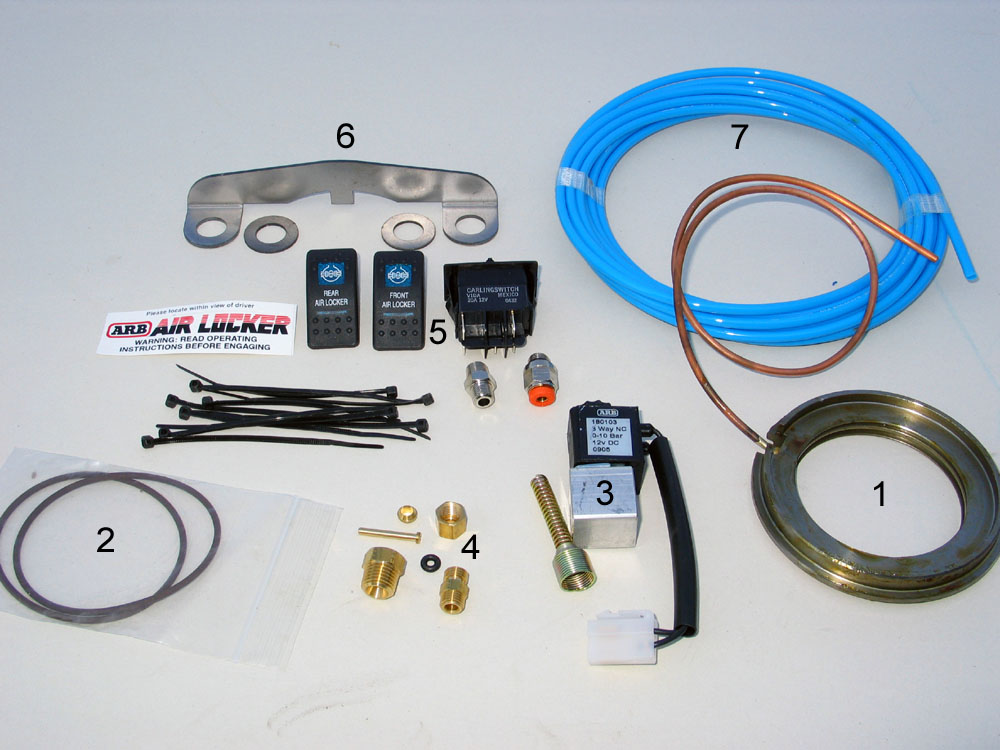 |
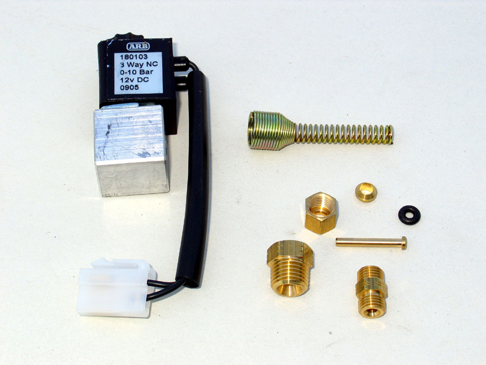
Apart from the locker itself, the box also contains: 1. The seal housing with seal housing tube attached |
||||||||||||||||||||||||||||||||||||||||||||||||||||||||||||||||||||||||||||||||||||||||||||||||||||||||||||||||||||||||||||||||||||||||||||||||||||||||||||||||||||||||||||||||||||||||||||||||||||||||||||||||||||||||||||||||||||||||||||||||||||||||||||||||||||||||||||||||||||||||||||||||||||||||||||||||||||||||||||||||||||||||||||||||||||||||||||||||||||||||||||||||||||||||||||||||||||||||||||||||||||||||||||||||||||
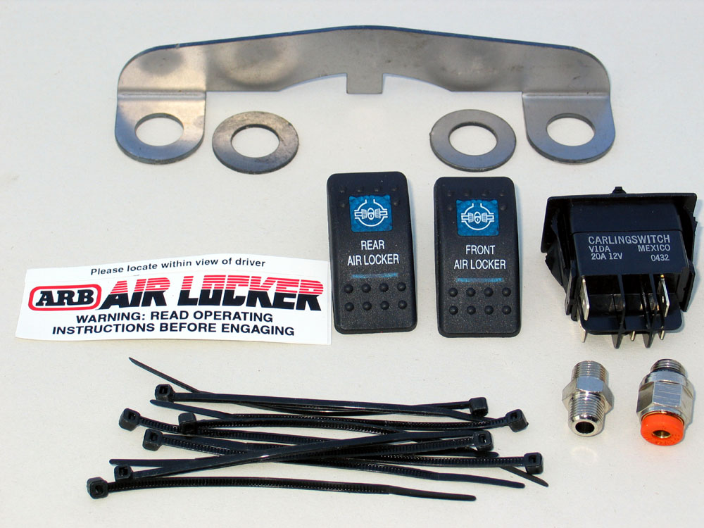 |
Close-up shot of the seal housing bracket and the activation switch. The two small, silver-coloured fittings on the lower right are for connecting the solenoid to the air source tank. The switches are nice quality units, have a cool blue back light, and have snazzy graphics on them. |
||||||||||||||||||||||||||||||||||||||||||||||||||||||||||||||||||||||||||||||||||||||||||||||||||||||||||||||||||||||||||||||||||||||||||||||||||||||||||||||||||||||||||||||||||||||||||||||||||||||||||||||||||||||||||||||||||||||||||||||||||||||||||||||||||||||||||||||||||||||||||||||||||||||||||||||||||||||||||||||||||||||||||||||||||||||||||||||||||||||||||||||||||||||||||||||||||||||||||||||||||||||||||||||||||||
 |
Close-up of the electro-pneumatic solenoid and the air-line to seal housing tube fittings. | ||||||||||||||||||||||||||||||||||||||||||||||||||||||||||||||||||||||||||||||||||||||||||||||||||||||||||||||||||||||||||||||||||||||||||||||||||||||||||||||||||||||||||||||||||||||||||||||||||||||||||||||||||||||||||||||||||||||||||||||||||||||||||||||||||||||||||||||||||||||||||||||||||||||||||||||||||||||||||||||||||||||||||||||||||||||||||||||||||||||||||||||||||||||||||||||||||||||||||||||||||||||||||||||||||||
ARB NomenclatureThe following exploded diagram and parts list are taken directly from the ARB installation manual and will help you to understand the rest of the article.
How the ARB WorksTo understand how the ARB air locker operates, refer to this modified version of the exploded diagram and read the description that follows.
The air flow is represented by the red arrows. When the locker is locked - air pressure is supplied through the seal housing tube to the seal housing (#14). It exits the port in the seal housing but is prevented from escaping by the two seal housing O-rings (#15), located between the seal housing and the seal housing running surface of the carrier. As such, the air pressurizes the cavity between the O-rings, the seal housing, and the seal housing running surface. There is a port in the seal housing running surface that directs the air into the differential where it pushes on the clutch gear (#4) that slides on the coarse splined part of the carrier (blue arrow). The clutch gear compresses the return springs (#5), and engages the coarse external splines of the splined side gear (#18). The external splines of the side gear cannot be seen ion this picture, but the engagement action is illustrated by the yellow arrows. With the clutch gear simultaneously engaging the side gear (#18) and the carrier (blue arrow), the ARB is now completely, positively locked and will act as a spool. InstallationStep 1 - Tear Down |
|||||||||||||||||||||||||||||||||||||||||||||||||||||||||||||||||||||||||||||||||||||||||||||||||||||||||||||||||||||||||||||||||||||||||||||||||||||||||||||||||||||||||||||||||||||||||||||||||||||||||||||||||||||||||||||||||||||||||||||||||||||||||||||||||||||||||||||||||||||||||||||||||||||||||||||||||||||||||||||||||||||||||||||||||||||||||||||||||||||||||||||||||||||||||||||||||||||||||||||||||||||||||||||||||||||
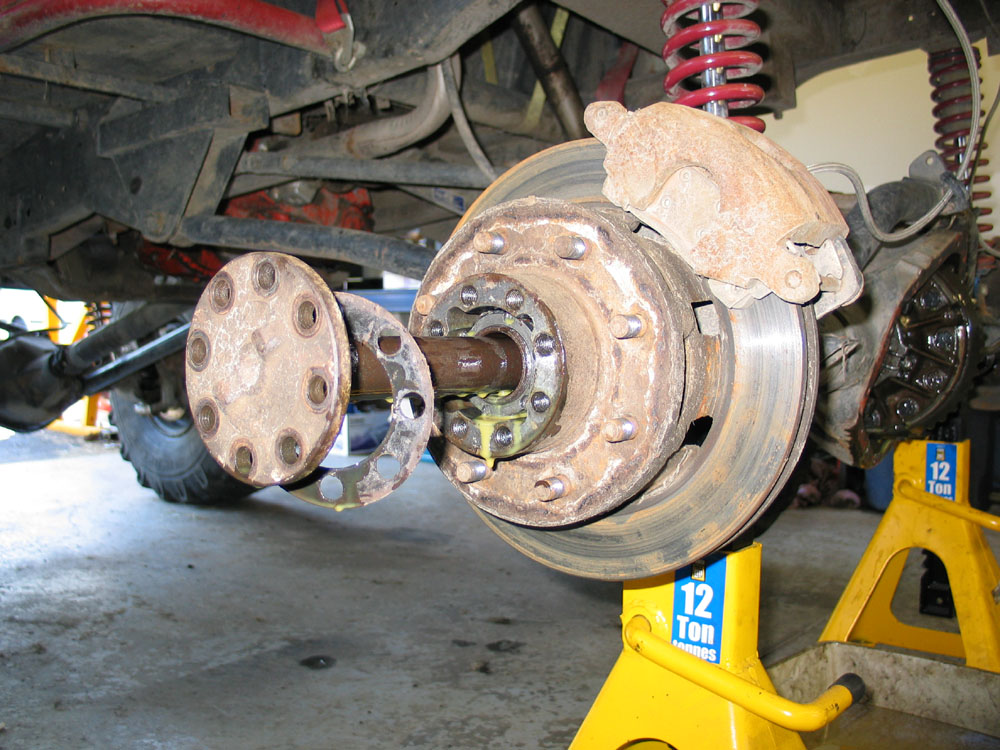 |
Loosen lug-nuts then jack up rear axle and secure safely on jack stands. Remove wheels. Remove the axle-flange to hub bolts and remove the axle shafts from the axle. |
||||||||||||||||||||||||||||||||||||||||||||||||||||||||||||||||||||||||||||||||||||||||||||||||||||||||||||||||||||||||||||||||||||||||||||||||||||||||||||||||||||||||||||||||||||||||||||||||||||||||||||||||||||||||||||||||||||||||||||||||||||||||||||||||||||||||||||||||||||||||||||||||||||||||||||||||||||||||||||||||||||||||||||||||||||||||||||||||||||||||||||||||||||||||||||||||||||||||||||||||||||||||||||||||||||
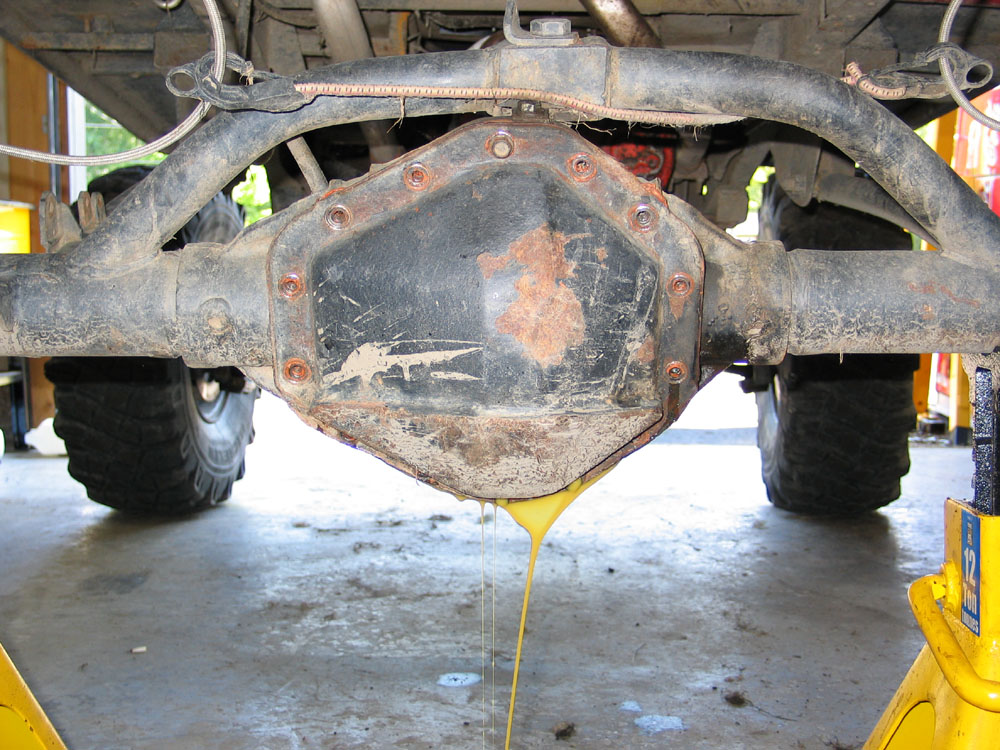 |
Remove the diff cover and drain the gear oil. Thoroughly clean the cover ready for installation. | ||||||||||||||||||||||||||||||||||||||||||||||||||||||||||||||||||||||||||||||||||||||||||||||||||||||||||||||||||||||||||||||||||||||||||||||||||||||||||||||||||||||||||||||||||||||||||||||||||||||||||||||||||||||||||||||||||||||||||||||||||||||||||||||||||||||||||||||||||||||||||||||||||||||||||||||||||||||||||||||||||||||||||||||||||||||||||||||||||||||||||||||||||||||||||||||||||||||||||||||||||||||||||||||||||||
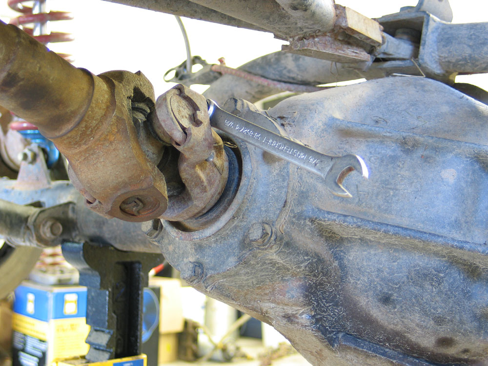 |
Remove the driveshaft U-bolts or straps and disconnect the driveshaft from the pinion yoke. | ||||||||||||||||||||||||||||||||||||||||||||||||||||||||||||||||||||||||||||||||||||||||||||||||||||||||||||||||||||||||||||||||||||||||||||||||||||||||||||||||||||||||||||||||||||||||||||||||||||||||||||||||||||||||||||||||||||||||||||||||||||||||||||||||||||||||||||||||||||||||||||||||||||||||||||||||||||||||||||||||||||||||||||||||||||||||||||||||||||||||||||||||||||||||||||||||||||||||||||||||||||||||||||||||||||
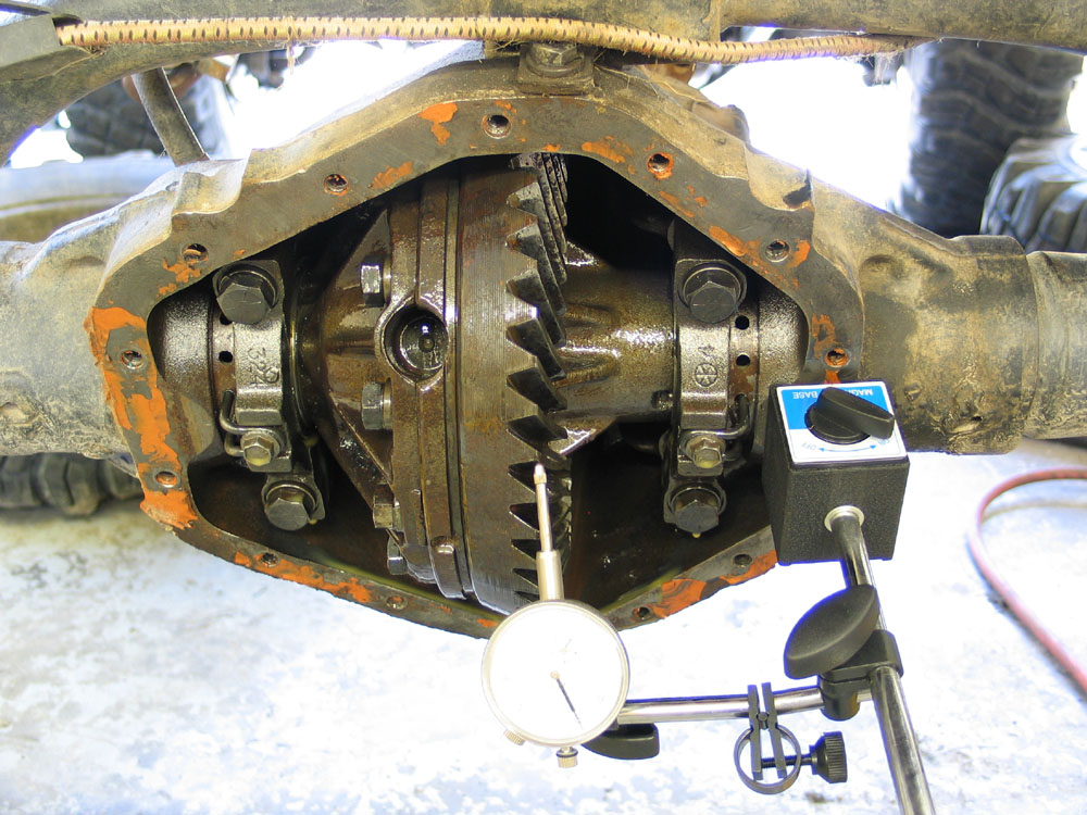 |
Before tearing down the diff, check the existing backlash with a dial-indicator. The reason you want to check it now, is so that you can re-install the same gears with the original backlash (assuming it was within spec) to avoid changing the gear tooth contact pattern since the gears have broken in together at this lash. In many axles this wouldn't even be an option, but where the 14-Bolt has such a wide range of acceptable backlash (0.003" - 0.012") it can be worth checking if you're going to be re-installing the same gears. |
||||||||||||||||||||||||||||||||||||||||||||||||||||||||||||||||||||||||||||||||||||||||||||||||||||||||||||||||||||||||||||||||||||||||||||||||||||||||||||||||||||||||||||||||||||||||||||||||||||||||||||||||||||||||||||||||||||||||||||||||||||||||||||||||||||||||||||||||||||||||||||||||||||||||||||||||||||||||||||||||||||||||||||||||||||||||||||||||||||||||||||||||||||||||||||||||||||||||||||||||||||||||||||||||||||
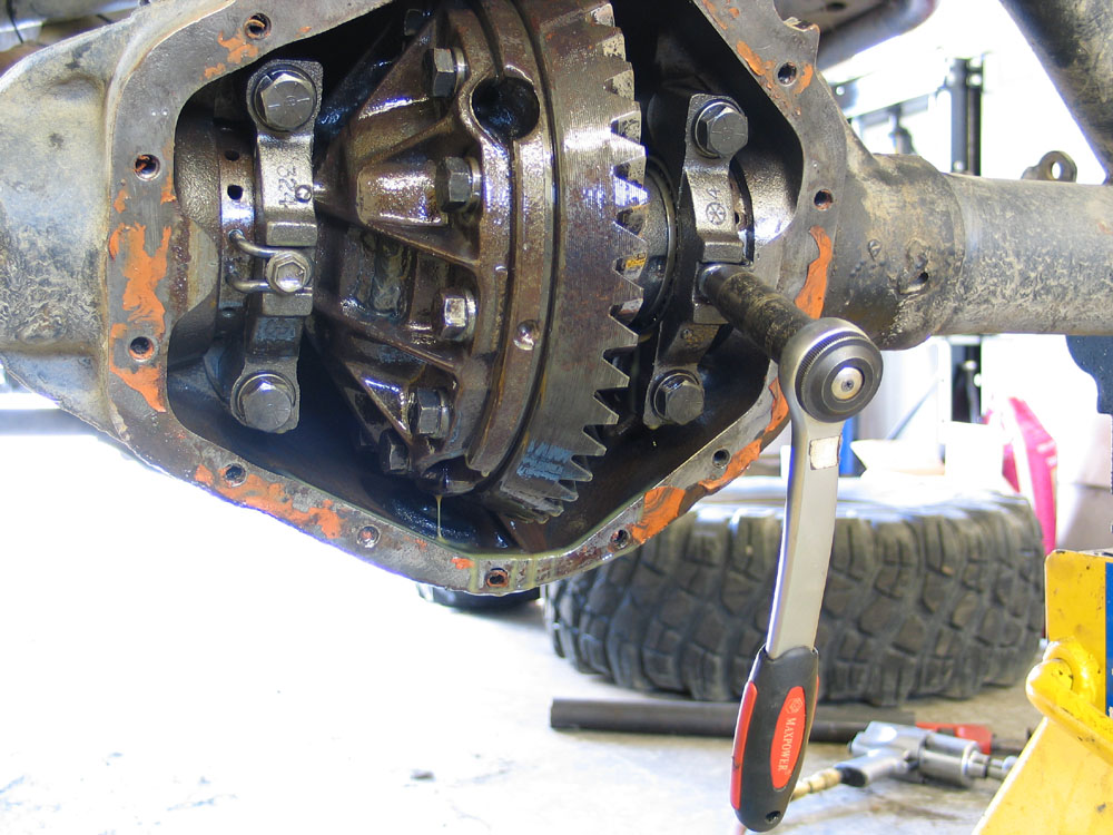 |
Remove the bolts securing the adjusting nut locks. Remove the adjusting nut locks. Mark the carrier bearing caps so that they can be re-installed in exactly the same orientation. Remove the bearing caps and bolts. |
||||||||||||||||||||||||||||||||||||||||||||||||||||||||||||||||||||||||||||||||||||||||||||||||||||||||||||||||||||||||||||||||||||||||||||||||||||||||||||||||||||||||||||||||||||||||||||||||||||||||||||||||||||||||||||||||||||||||||||||||||||||||||||||||||||||||||||||||||||||||||||||||||||||||||||||||||||||||||||||||||||||||||||||||||||||||||||||||||||||||||||||||||||||||||||||||||||||||||||||||||||||||||||||||||||
 |
Loosen the adjusting nuts so that the carrier can be removed, and carefully remove the carrier. It's best to use the proper spanner tool, but a #2 Phillips screwdriver will do. The right adjusting nut is loosened by moving the screwdriver handle DOWN. The left adjusting nut is loosened by moving the screwdriver handle UP. |
||||||||||||||||||||||||||||||||||||||||||||||||||||||||||||||||||||||||||||||||||||||||||||||||||||||||||||||||||||||||||||||||||||||||||||||||||||||||||||||||||||||||||||||||||||||||||||||||||||||||||||||||||||||||||||||||||||||||||||||||||||||||||||||||||||||||||||||||||||||||||||||||||||||||||||||||||||||||||||||||||||||||||||||||||||||||||||||||||||||||||||||||||||||||||||||||||||||||||||||||||||||||||||||||||||
 |
Tag and keep the carrier bearing cups separate so that they can be re-installed on their original sides. Remove the carrier bearings from the carrier, tag them, and keep them separate with their cups. Here I am using a clamshell-style carrier bearing puller. In the past I have used cheap, 2-jaw pullers (that had to have the legs ground to fit in the carrier reliefs below the carrier bearings), hammer and chisel, heel-style pry-bars, and who knows what to remove carrier bearings. |
||||||||||||||||||||||||||||||||||||||||||||||||||||||||||||||||||||||||||||||||||||||||||||||||||||||||||||||||||||||||||||||||||||||||||||||||||||||||||||||||||||||||||||||||||||||||||||||||||||||||||||||||||||||||||||||||||||||||||||||||||||||||||||||||||||||||||||||||||||||||||||||||||||||||||||||||||||||||||||||||||||||||||||||||||||||||||||||||||||||||||||||||||||||||||||||||||||||||||||||||||||||||||||||||||||
 |
None of these methods works very well, all seem to damage the bearing during removal, and frankly I was tired of them. On top of that, the design of the stock 14-Bolt carrier leaves virtually no room to get a leg-style puller or a bearing separator in behind the carrier bearings. For more details check out my review of the Yukon Clamshell Bearing Puller from Randy's Ring & Pinion |
||||||||||||||||||||||||||||||||||||||||||||||||||||||||||||||||||||||||||||||||||||||||||||||||||||||||||||||||||||||||||||||||||||||||||||||||||||||||||||||||||||||||||||||||||||||||||||||||||||||||||||||||||||||||||||||||||||||||||||||||||||||||||||||||||||||||||||||||||||||||||||||||||||||||||||||||||||||||||||||||||||||||||||||||||||||||||||||||||||||||||||||||||||||||||||||||||||||||||||||||||||||||||||||||||||
 |
Use a clamp or similar device to keep pressure on the two halves of the carrier as you remove the ring gear bolts, as spring pressure from the differential will try and force the two halves apart. Remove and DISCARD the old ring gear bolts and lock washers. Then tap the ring gear free from the carrier. |
||||||||||||||||||||||||||||||||||||||||||||||||||||||||||||||||||||||||||||||||||||||||||||||||||||||||||||||||||||||||||||||||||||||||||||||||||||||||||||||||||||||||||||||||||||||||||||||||||||||||||||||||||||||||||||||||||||||||||||||||||||||||||||||||||||||||||||||||||||||||||||||||||||||||||||||||||||||||||||||||||||||||||||||||||||||||||||||||||||||||||||||||||||||||||||||||||||||||||||||||||||||||||||||||||||
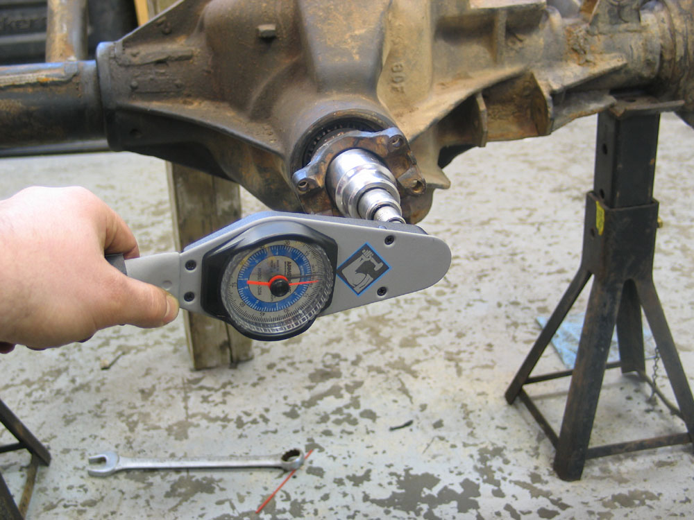 |
Before removing the pinion nut, and with the carrier removed, it can be beneficial to check the pinion bearing preload. This will give you some indication as to the health (or in my case - lack thereof) of your pinion bearings. To measure pinion bearing preload - use a beam- or dial-type inch-pound torque wrench on the pinion nut and measure the torque required to rotate the pinion. Do not read the initial torque it takes to start the pinion turning, but rather the steady torque it takes to keep the pinion rotating. The spec is 5-15 in/lbs for used bearings. If pinion preload is within spec and you are not changing the pinion bearings, you needn't remove the pinion bearing retainer nor even loosen the pinion nut. Note: Picture actually shows D60 axle, but concept is the same. |
||||||||||||||||||||||||||||||||||||||||||||||||||||||||||||||||||||||||||||||||||||||||||||||||||||||||||||||||||||||||||||||||||||||||||||||||||||||||||||||||||||||||||||||||||||||||||||||||||||||||||||||||||||||||||||||||||||||||||||||||||||||||||||||||||||||||||||||||||||||||||||||||||||||||||||||||||||||||||||||||||||||||||||||||||||||||||||||||||||||||||||||||||||||||||||||||||||||||||||||||||||||||||||||||||||
 |
If pinion bearing preload is less than 5 in/lbs you can increase it slightly by securing the yoke from turning and then very carefully tightening the pinion nut in small increments. Stop and check the torque required to turn the pinion frequently while tightening. If you over-tighten the nut you will need to replace the crush sleeve. If you need to replace the pinion, pinion bearings, crush sleeve or pinion seal - refer to my 14-Bolt Gear Setup Article. |
||||||||||||||||||||||||||||||||||||||||||||||||||||||||||||||||||||||||||||||||||||||||||||||||||||||||||||||||||||||||||||||||||||||||||||||||||||||||||||||||||||||||||||||||||||||||||||||||||||||||||||||||||||||||||||||||||||||||||||||||||||||||||||||||||||||||||||||||||||||||||||||||||||||||||||||||||||||||||||||||||||||||||||||||||||||||||||||||||||||||||||||||||||||||||||||||||||||||||||||||||||||||||||||||||||
Assembling the ARB and Ring Gear |
|||||||||||||||||||||||||||||||||||||||||||||||||||||||||||||||||||||||||||||||||||||||||||||||||||||||||||||||||||||||||||||||||||||||||||||||||||||||||||||||||||||||||||||||||||||||||||||||||||||||||||||||||||||||||||||||||||||||||||||||||||||||||||||||||||||||||||||||||||||||||||||||||||||||||||||||||||||||||||||||||||||||||||||||||||||||||||||||||||||||||||||||||||||||||||||||||||||||||||||||||||||||||||||||||||||
 |
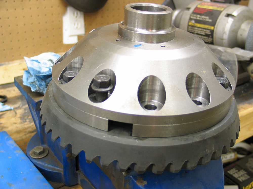
Clean the ring gear thoroughly before installing it on the ARB. Pay particular attention to ensuring the mounting surface is clean and burr-free and that all the bolt holes are clean, free from any grease or old thread-locking compound, and dry. Heat the ring-gear in a kitchen stove at 200°F for about 45 minutes to expand it slightly and ease assembly. Note that this step is recommended only for very clean gears - unless of course your spouse doesn't mind the aroma of baking gear oil! Never heat the ring gear with a flame as this will damage the hardened surfaces. In a pinch, you could heat an old ring gear in boiling water on a camp stove or the like. Carefully install the ring gear onto the ARB, tapping with a soft-faced hammer if necessary, being sure to line up the bolt holes. DO NOT use the bolts to pull the ring gear onto the locker as this will damage the ring gear bolts. |
||||||||||||||||||||||||||||||||||||||||||||||||||||||||||||||||||||||||||||||||||||||||||||||||||||||||||||||||||||||||||||||||||||||||||||||||||||||||||||||||||||||||||||||||||||||||||||||||||||||||||||||||||||||||||||||||||||||||||||||||||||||||||||||||||||||||||||||||||||||||||||||||||||||||||||||||||||||||||||||||||||||||||||||||||||||||||||||||||||||||||||||||||||||||||||||||||||||||||||||||||||||||||||||||||||
Note: It is at this stage that I must take one of the very few exceptions I have to the ARB instructions (as I said - they are excellent overall). However, the ARB instruction sheet includes this step: "Apply a thin film of high pressure grease to the ring gear shoulder of the Air Locker to prevent seizing." I fundamentally disagree with this step. First - the ring gear and air locker will spend their life running in an oil bath - it is very unlikely that seizing due to corrosion will ever happen. In fact, I have never seen a ring gear seized to its carrier. Some are very tight, it's true, but that's a good thing - a very good thing. More importantly though - you actually want a very high friction interface between the ring gear and the locker - you want the ring gear bolts to clamp the ring gear to the flange on the locker - thereby achieving friction between the two - and thereby keeping the ring gear attached to the locker, without having to rely solely on the ring gear bolts loaded in shear. I believe coating either side of this mating interface with grease - or anything else - would be highly counter-productive. Keep the surfaces clean and dry. |
|||||||||||||||||||||||||||||||||||||||||||||||||||||||||||||||||||||||||||||||||||||||||||||||||||||||||||||||||||||||||||||||||||||||||||||||||||||||||||||||||||||||||||||||||||||||||||||||||||||||||||||||||||||||||||||||||||||||||||||||||||||||||||||||||||||||||||||||||||||||||||||||||||||||||||||||||||||||||||||||||||||||||||||||||||||||||||||||||||||||||||||||||||||||||||||||||||||||||||||||||||||||||||||||||||||
 |
Apply a little high-strength thread locking compound to the ring gear bolts and carefully insert them. Don't go overboard with the thread locker - only a little is needed. I find the new gel kind from Loctite works very well. ALWAYS install new ring gear bolts - even if reusing the ring gear. Torque the ring gear bolts evenly, in two or three stages, using a crosswise pattern, to 120 ft/lbs. You will have to carefully clamp the locker in a vice to do this - using a rag or something similar to prevent damage to the locker. |
||||||||||||||||||||||||||||||||||||||||||||||||||||||||||||||||||||||||||||||||||||||||||||||||||||||||||||||||||||||||||||||||||||||||||||||||||||||||||||||||||||||||||||||||||||||||||||||||||||||||||||||||||||||||||||||||||||||||||||||||||||||||||||||||||||||||||||||||||||||||||||||||||||||||||||||||||||||||||||||||||||||||||||||||||||||||||||||||||||||||||||||||||||||||||||||||||||||||||||||||||||||||||||||||||||
 |
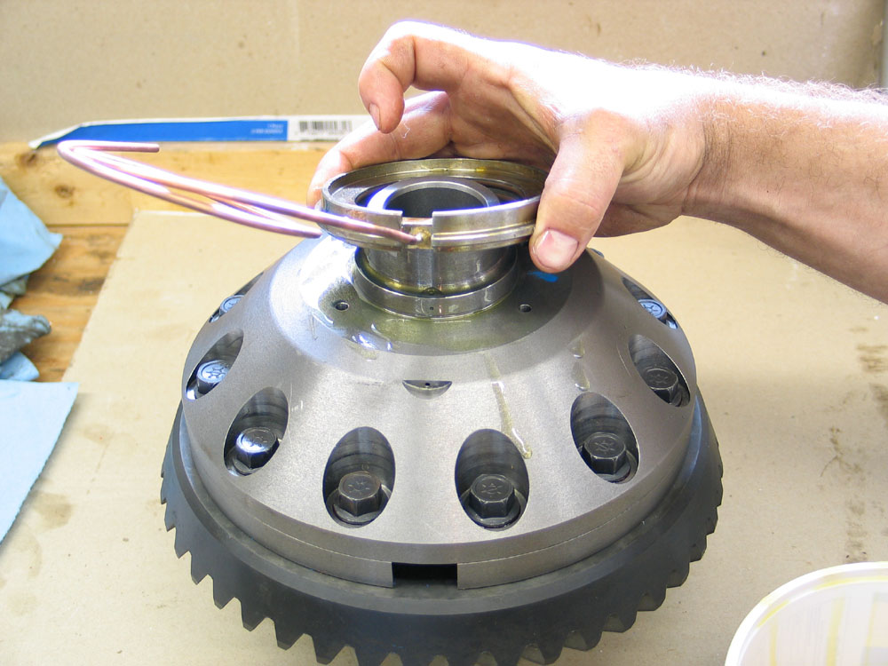
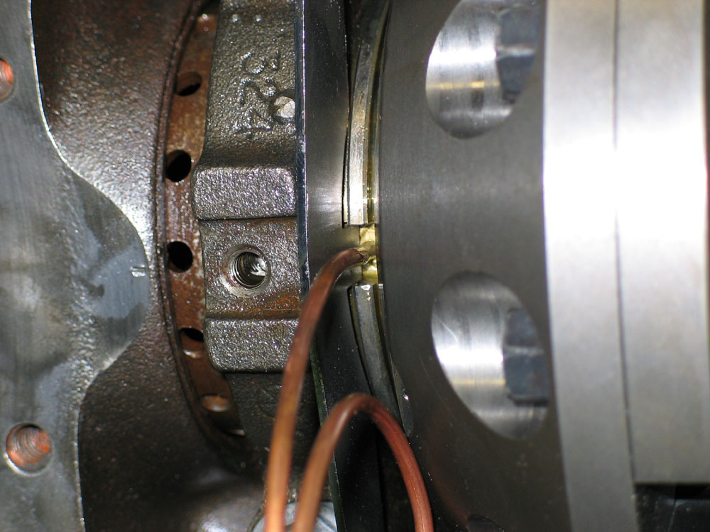
With the ring gear installed on the locker it is time for the most critical phase of the ARB install - installing the seal housing without pinching or twisting the O-rings. Remember the pit falls I was warning you about? This is one of the biggest. I'm pretty convinced that a lot of issues involving ARB's - air leaks and "eau de gear oil" in the cab - can be traced to an error at this stage of the install. So clear yourself some clean space to work, set the locker, seal housing, and O-rings in front of you, roll up your sleeves, and let's get it right the first time. |
||||||||||||||||||||||||||||||||||||||||||||||||||||||||||||||||||||||||||||||||||||||||||||||||||||||||||||||||||||||||||||||||||||||||||||||||||||||||||||||||||||||||||||||||||||||||||||||||||||||||||||||||||||||||||||||||||||||||||||||||||||||||||||||||||||||||||||||||||||||||||||||||||||||||||||||||||||||||||||||||||||||||||||||||||||||||||||||||||||||||||||||||||||||||||||||||||||||||||||||||||||||||||||||||||||
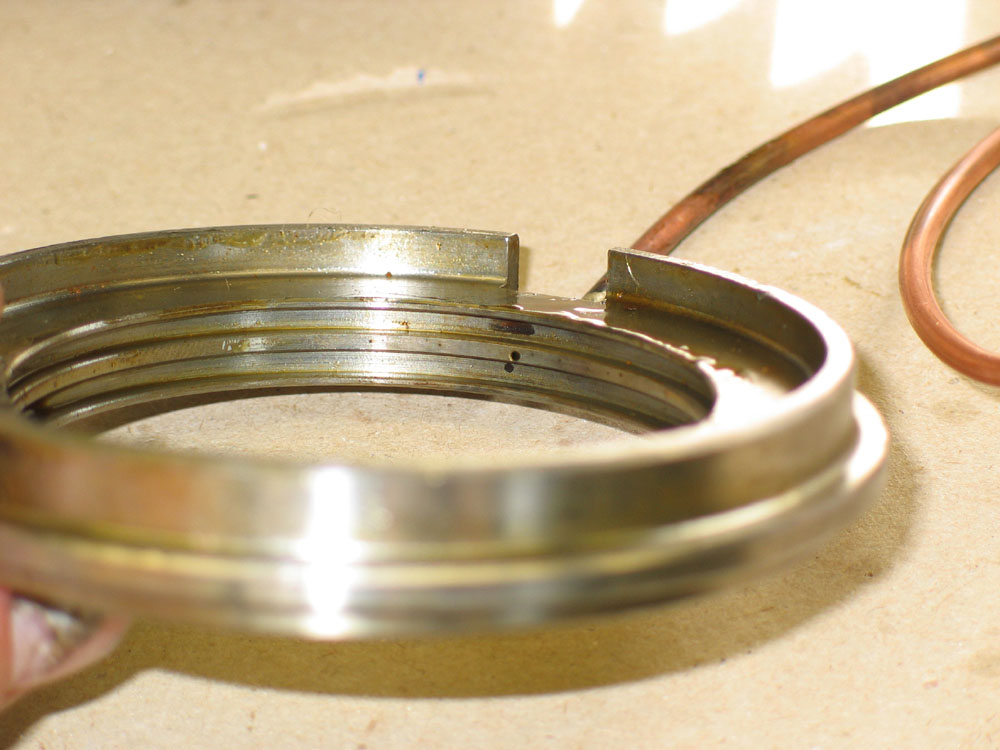 |
This is a close-up of the seal housing. You can see the air port on the centre ring. Air is supplied through the copper seal housing tube brazed onto the seal housing. It comes through the air port, and is sealed on either side by the O-rings. The seal housing itself sits on a specially machined journal just inside the carrier bearing journal. The seal housing is prevented from rotating on the journal by the seal housing bracket. The seal housing journal also has an air port that directs the air pressure inside the ARB to activate the locking mechanism. The two O-rings seal the air from escaping and at the same time the locker must rotate inside them without damaging or excessively wearing the O-rings. For this reason, the O-rings MUST be properly and completely lubricated before installation, must be installed in the seal housing without being twisted or deformed, and then the seal housing and /-ring assembly must be installed on the locker without pinching, twisting, deforming, or damaging the O-rings. |
||||||||||||||||||||||||||||||||||||||||||||||||||||||||||||||||||||||||||||||||||||||||||||||||||||||||||||||||||||||||||||||||||||||||||||||||||||||||||||||||||||||||||||||||||||||||||||||||||||||||||||||||||||||||||||||||||||||||||||||||||||||||||||||||||||||||||||||||||||||||||||||||||||||||||||||||||||||||||||||||||||||||||||||||||||||||||||||||||||||||||||||||||||||||||||||||||||||||||||||||||||||||||||||||||||
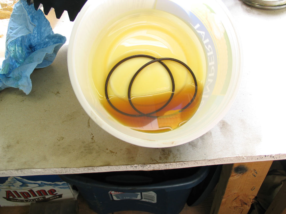 |
First, generously lubricate the O-rings in gear oil. Generously lubricate the seal housing with gear oil. |
||||||||||||||||||||||||||||||||||||||||||||||||||||||||||||||||||||||||||||||||||||||||||||||||||||||||||||||||||||||||||||||||||||||||||||||||||||||||||||||||||||||||||||||||||||||||||||||||||||||||||||||||||||||||||||||||||||||||||||||||||||||||||||||||||||||||||||||||||||||||||||||||||||||||||||||||||||||||||||||||||||||||||||||||||||||||||||||||||||||||||||||||||||||||||||||||||||||||||||||||||||||||||||||||||||
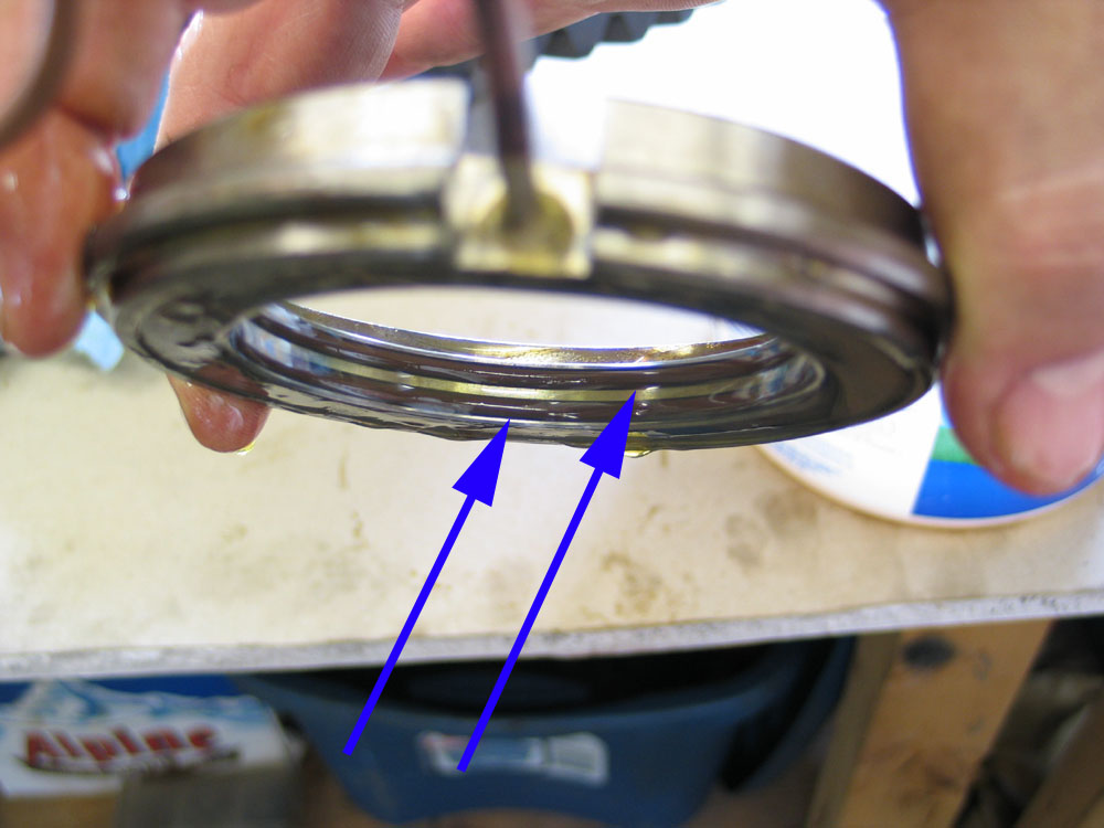 |
Carefully install an /-ring in each groove of the seal housing. Make sure they are completely seated in the grooves and that they are not twisted or deformed. The blue arrows show the O-rings properly installed in the seal housing. |
||||||||||||||||||||||||||||||||||||||||||||||||||||||||||||||||||||||||||||||||||||||||||||||||||||||||||||||||||||||||||||||||||||||||||||||||||||||||||||||||||||||||||||||||||||||||||||||||||||||||||||||||||||||||||||||||||||||||||||||||||||||||||||||||||||||||||||||||||||||||||||||||||||||||||||||||||||||||||||||||||||||||||||||||||||||||||||||||||||||||||||||||||||||||||||||||||||||||||||||||||||||||||||||||||||
 |
Generously lubricate the seal housing running surface (just below the bearing journal) with gear oil. | ||||||||||||||||||||||||||||||||||||||||||||||||||||||||||||||||||||||||||||||||||||||||||||||||||||||||||||||||||||||||||||||||||||||||||||||||||||||||||||||||||||||||||||||||||||||||||||||||||||||||||||||||||||||||||||||||||||||||||||||||||||||||||||||||||||||||||||||||||||||||||||||||||||||||||||||||||||||||||||||||||||||||||||||||||||||||||||||||||||||||||||||||||||||||||||||||||||||||||||||||||||||||||||||||||||
 |
Orient the seal housing as shown, with the seal housing flange closest to the air locker, and carefully install it by sliding it into place with a gentle twisting motion. It's very important to have everything well lubricated, and to complete this step with great care as you must ensure the O-rings do not get pinched or twisted. Naturally, the O-rings are a tight fit onto the running surface and the seal housing will almost "pop" into place as you gently rotate the seal housing while pressing it on. Once again - if you allow the O-rings to twist while installing the seal housing, they will not seal properly - and this will allow oil contamination of the air system - resulting in the complaint of gear-oil odour from the switches when deactivating the locker. |
||||||||||||||||||||||||||||||||||||||||||||||||||||||||||||||||||||||||||||||||||||||||||||||||||||||||||||||||||||||||||||||||||||||||||||||||||||||||||||||||||||||||||||||||||||||||||||||||||||||||||||||||||||||||||||||||||||||||||||||||||||||||||||||||||||||||||||||||||||||||||||||||||||||||||||||||||||||||||||||||||||||||||||||||||||||||||||||||||||||||||||||||||||||||||||||||||||||||||||||||||||||||||||||||||||
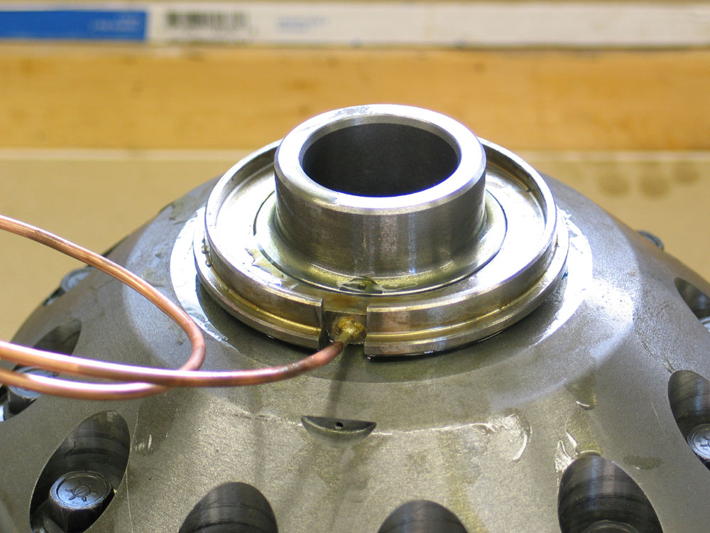 |
Properly installed it will look like this. Note the orientation of the seal housing - with the largest diameter (the flange) up against the locker. | ||||||||||||||||||||||||||||||||||||||||||||||||||||||||||||||||||||||||||||||||||||||||||||||||||||||||||||||||||||||||||||||||||||||||||||||||||||||||||||||||||||||||||||||||||||||||||||||||||||||||||||||||||||||||||||||||||||||||||||||||||||||||||||||||||||||||||||||||||||||||||||||||||||||||||||||||||||||||||||||||||||||||||||||||||||||||||||||||||||||||||||||||||||||||||||||||||||||||||||||||||||||||||||||||||||
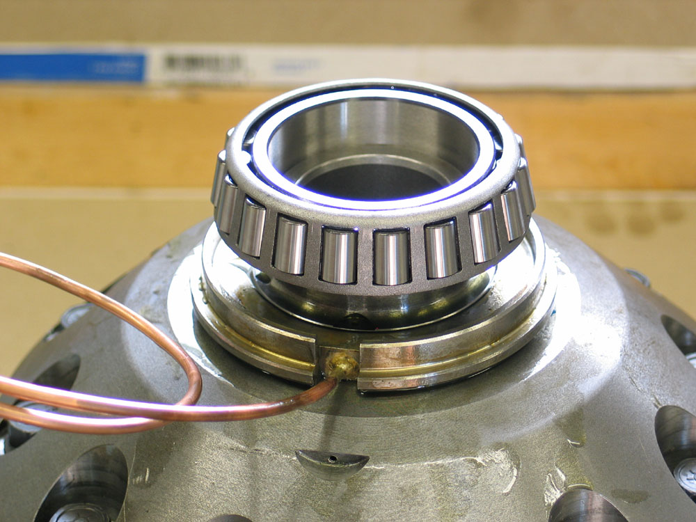 |
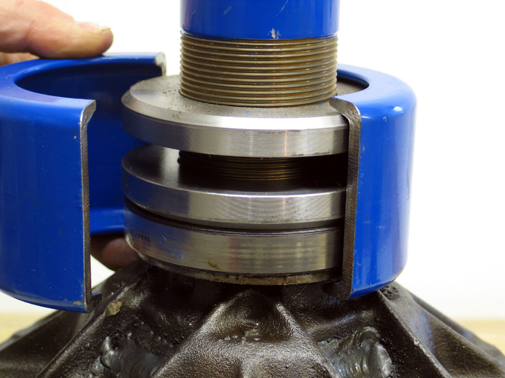
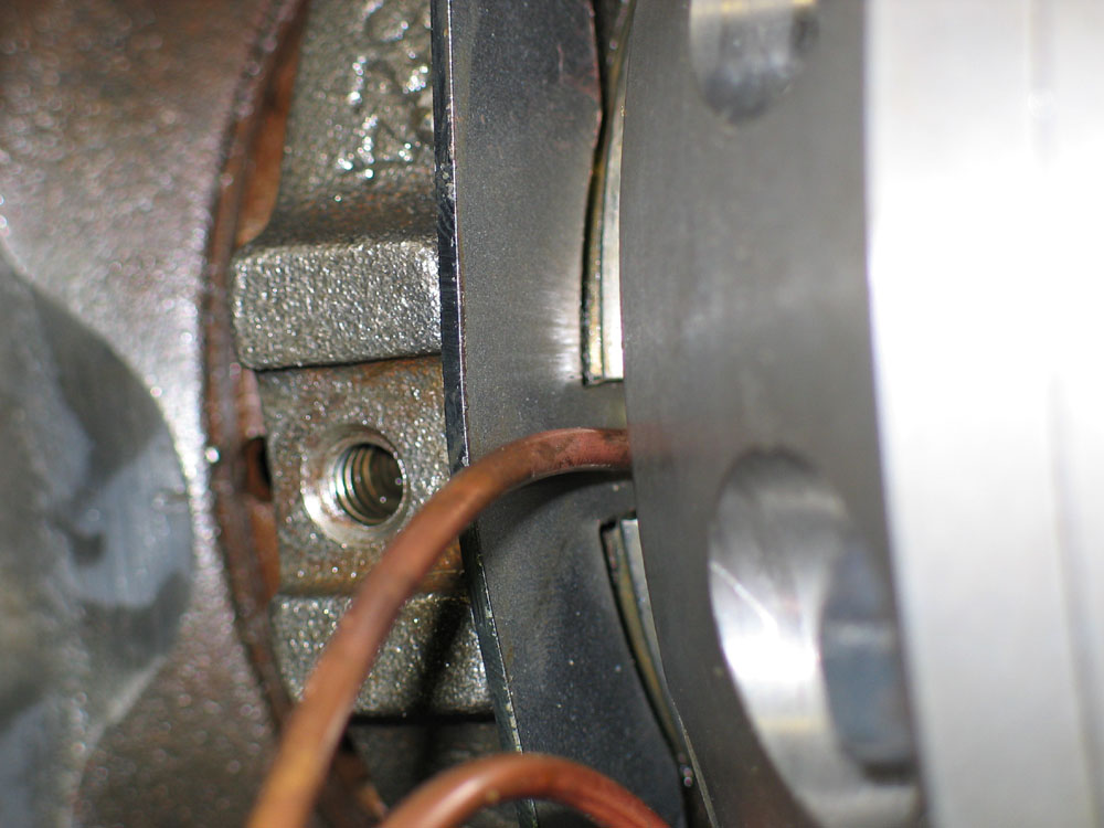
The next step is to install the carrier bearings. This can be a little tricky with the seal housing installed as you have to be very careful of the seal housing tube. Where the copper tube is brazed onto the seal housing, the attachment is quite fragile and the locker is heavy and unwieldy. Great care is required to avoid damage. Install the left (non ring gear side) bearing first. Carefully place the bearing cone square on the journal. |
||||||||||||||||||||||||||||||||||||||||||||||||||||||||||||||||||||||||||||||||||||||||||||||||||||||||||||||||||||||||||||||||||||||||||||||||||||||||||||||||||||||||||||||||||||||||||||||||||||||||||||||||||||||||||||||||||||||||||||||||||||||||||||||||||||||||||||||||||||||||||||||||||||||||||||||||||||||||||||||||||||||||||||||||||||||||||||||||||||||||||||||||||||||||||||||||||||||||||||||||||||||||||||||||||||
 |
Then press it into place until the bearing seats firmly against the shoulder of the bearing journal. I found that the bearing seated before the driver I was using bottomed on the journal. Note that there will be very little clearance between the seal housing and the bearing once the bearing is fully seated - this is normal and perfectly OK. Obviously there shouldn't be any actual contact between the two parts. |
||||||||||||||||||||||||||||||||||||||||||||||||||||||||||||||||||||||||||||||||||||||||||||||||||||||||||||||||||||||||||||||||||||||||||||||||||||||||||||||||||||||||||||||||||||||||||||||||||||||||||||||||||||||||||||||||||||||||||||||||||||||||||||||||||||||||||||||||||||||||||||||||||||||||||||||||||||||||||||||||||||||||||||||||||||||||||||||||||||||||||||||||||||||||||||||||||||||||||||||||||||||||||||||||||||
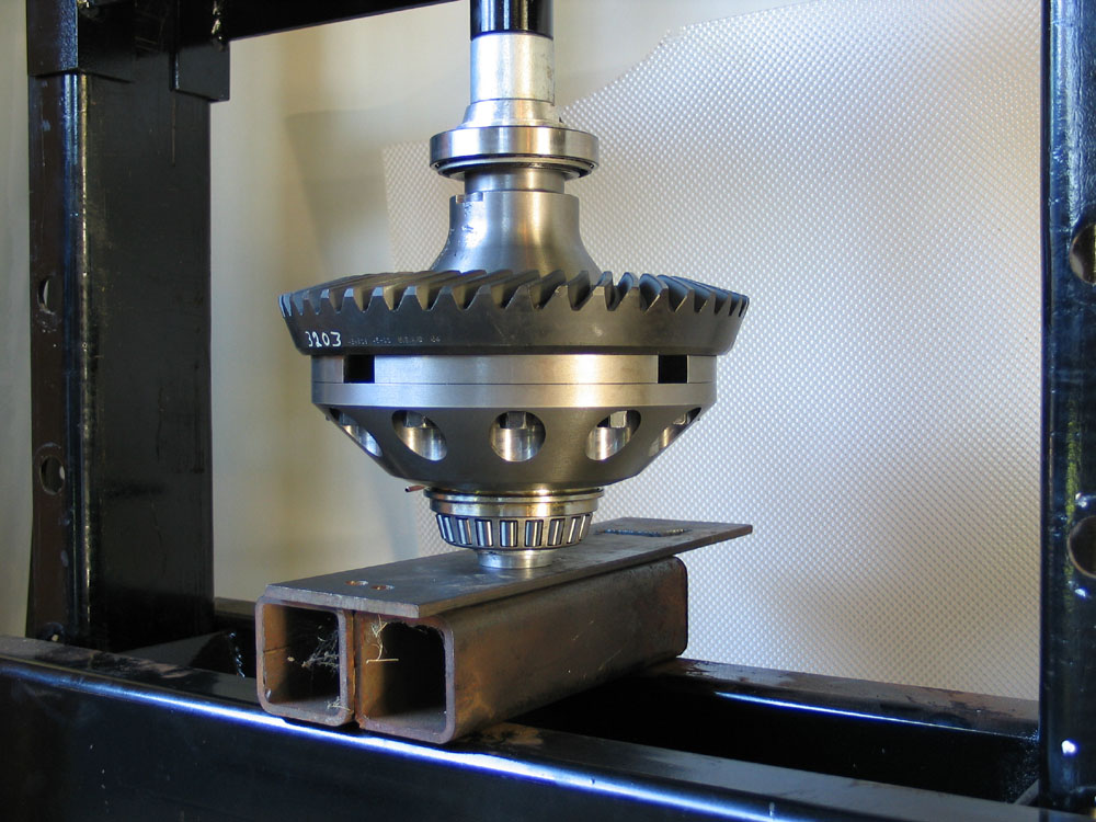 |
The right side is just a little more tricky since you already have a bearing installed on the opposite side. This is because the rollers and cage protrude slightly above the end of the carrier. If you were to simply set the carrier on the press bed and press on the right side bearing, you would damage the cage of the other bearing, ruining it. To avoid this, I placed a small driver underneath the carrier that fit inside the ID of the bearing, against the end of the journal. This way, the load will transmit through the carrier journal to the driver, to the press, without damaging the installed bearing. |
||||||||||||||||||||||||||||||||||||||||||||||||||||||||||||||||||||||||||||||||||||||||||||||||||||||||||||||||||||||||||||||||||||||||||||||||||||||||||||||||||||||||||||||||||||||||||||||||||||||||||||||||||||||||||||||||||||||||||||||||||||||||||||||||||||||||||||||||||||||||||||||||||||||||||||||||||||||||||||||||||||||||||||||||||||||||||||||||||||||||||||||||||||||||||||||||||||||||||||||||||||||||||||||||||||
 |
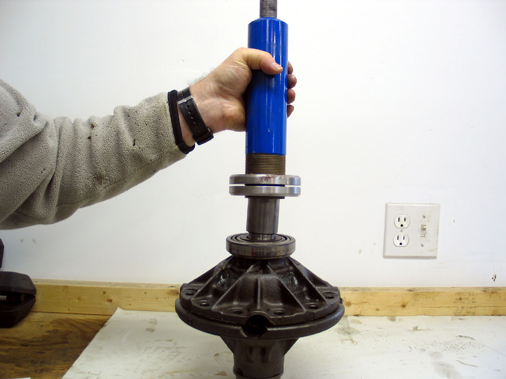
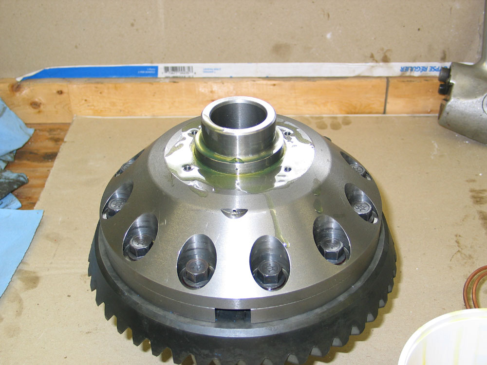
I then pressed on the bearing, making sure to press only against the inner ring of the bearing cone, and not against the cage or rollers. At this point the ARB is fully assembled ready for installation and you can move on to the job of drilling and tapping the axle housing for the air line. |
||||||||||||||||||||||||||||||||||||||||||||||||||||||||||||||||||||||||||||||||||||||||||||||||||||||||||||||||||||||||||||||||||||||||||||||||||||||||||||||||||||||||||||||||||||||||||||||||||||||||||||||||||||||||||||||||||||||||||||||||||||||||||||||||||||||||||||||||||||||||||||||||||||||||||||||||||||||||||||||||||||||||||||||||||||||||||||||||||||||||||||||||||||||||||||||||||||||||||||||||||||||||||||||||||||
Drilling and Tapping the Axle Housing for the Air Line |
|||||||||||||||||||||||||||||||||||||||||||||||||||||||||||||||||||||||||||||||||||||||||||||||||||||||||||||||||||||||||||||||||||||||||||||||||||||||||||||||||||||||||||||||||||||||||||||||||||||||||||||||||||||||||||||||||||||||||||||||||||||||||||||||||||||||||||||||||||||||||||||||||||||||||||||||||||||||||||||||||||||||||||||||||||||||||||||||||||||||||||||||||||||||||||||||||||||||||||||||||||||||||||||||||||||
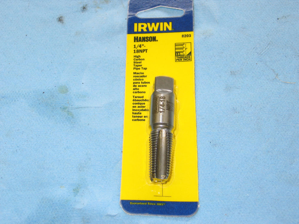 |
You will need a 1/4"-18NPT tap to cut National Pipe Taper (NPT) threads. NPT threads are tapered threads common in plumbing and hydraulics. As the name suggests, the threads are actually slightly tapered, so that a leak-free fit can be obtained as the parts are screwed together. A 1/4" NPT fitting will have an actual threaded OD of nearly half an inch, and requires a 7/16" hole be drilled for tapping the hole. The proper tap may be a challenge to find, but should be available from a good machine shop tool supplier, hydraulics outlet, or other quality tool supplier. It will have an OD of 0.459", have 18 threads per inch, and will taper between 23/32 and 27/32 inches per foot. | ||||||||||||||||||||||||||||||||||||||||||||||||||||||||||||||||||||||||||||||||||||||||||||||||||||||||||||||||||||||||||||||||||||||||||||||||||||||||||||||||||||||||||||||||||||||||||||||||||||||||||||||||||||||||||||||||||||||||||||||||||||||||||||||||||||||||||||||||||||||||||||||||||||||||||||||||||||||||||||||||||||||||||||||||||||||||||||||||||||||||||||||||||||||||||||||||||||||||||||||||||||||||||||||||||||
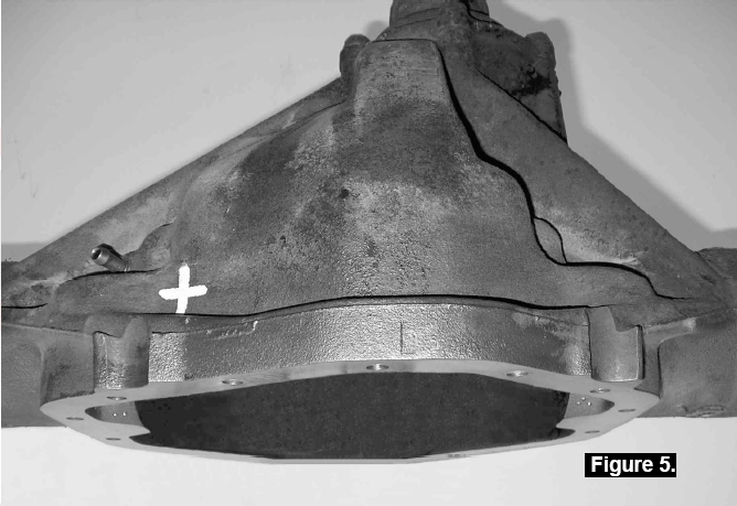 |
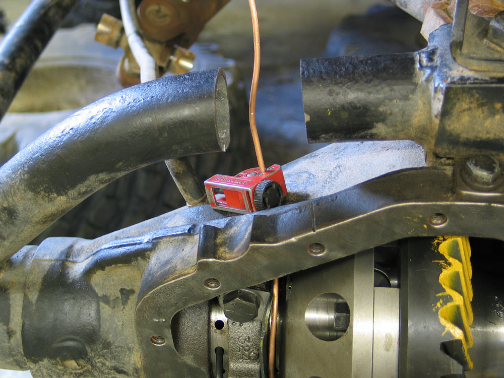
The first step is to carefully drill a 7/16" hole through the housing in the position indicated by the white cross. Picture from the ARB installation manual, courtesy ARB. |
||||||||||||||||||||||||||||||||||||||||||||||||||||||||||||||||||||||||||||||||||||||||||||||||||||||||||||||||||||||||||||||||||||||||||||||||||||||||||||||||||||||||||||||||||||||||||||||||||||||||||||||||||||||||||||||||||||||||||||||||||||||||||||||||||||||||||||||||||||||||||||||||||||||||||||||||||||||||||||||||||||||||||||||||||||||||||||||||||||||||||||||||||||||||||||||||||||||||||||||||||||||||||||||||||||
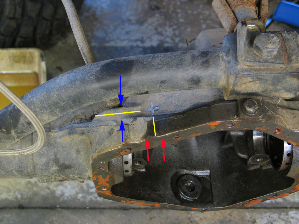 |
It can be a little nerve racking, as drilling into the housing is not something that can be terribly easily fixed if you get it wrong - the cast iron of the 14-Bolt housing does not weld well. I used the following method to find the location to drill: Just rear of the axle breather, there is a small shape (between the blue arrows in the pic). Draw a line down the middle of this shape - represented in the picture by the longer yellow line. On the top of the housing, there is a small flat area (between the red arrows in the pic.) Draw another line just to the right of the middle of this area - shown in the pic by the short yellow line. The correct location to drill the hole is where the two yellow lines intersect - shown by the silver cross I drew on my housing with a Sharpie. Make sure you centre-punch the target to get the hole started accurately, and use rags to cover the pinion and collect the metal filings. |
||||||||||||||||||||||||||||||||||||||||||||||||||||||||||||||||||||||||||||||||||||||||||||||||||||||||||||||||||||||||||||||||||||||||||||||||||||||||||||||||||||||||||||||||||||||||||||||||||||||||||||||||||||||||||||||||||||||||||||||||||||||||||||||||||||||||||||||||||||||||||||||||||||||||||||||||||||||||||||||||||||||||||||||||||||||||||||||||||||||||||||||||||||||||||||||||||||||||||||||||||||||||||||||||||||
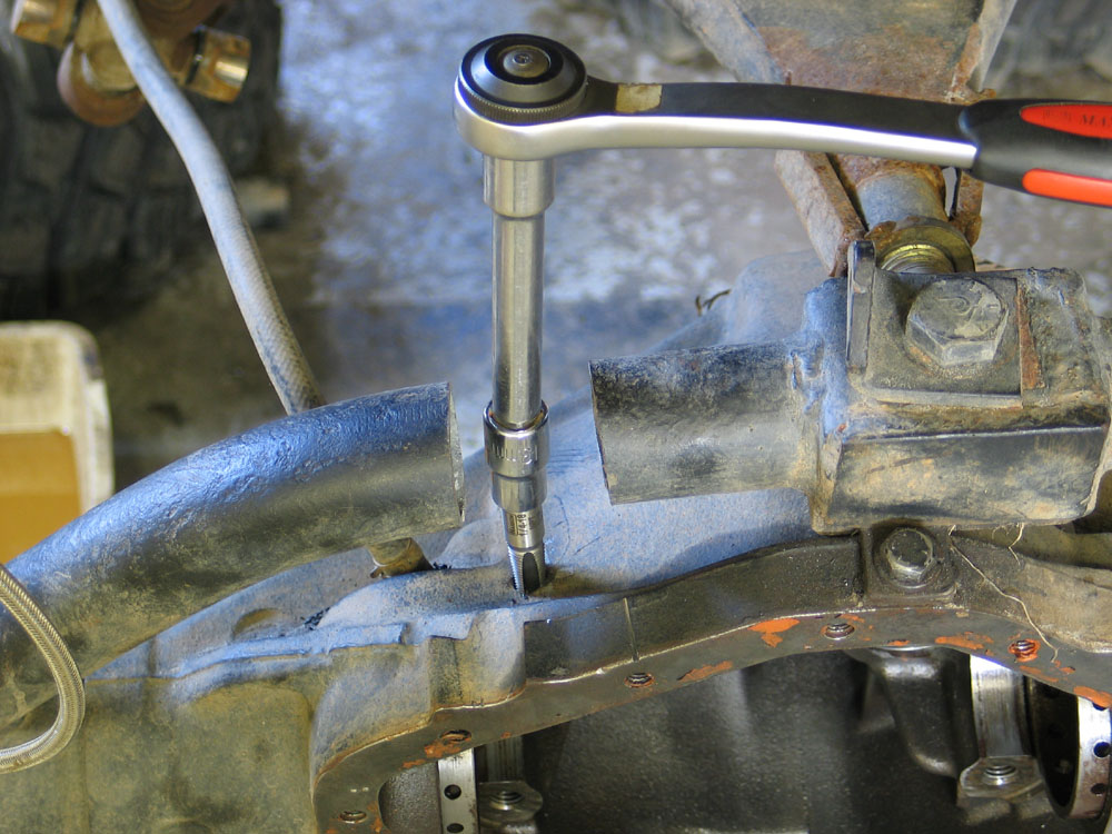 |
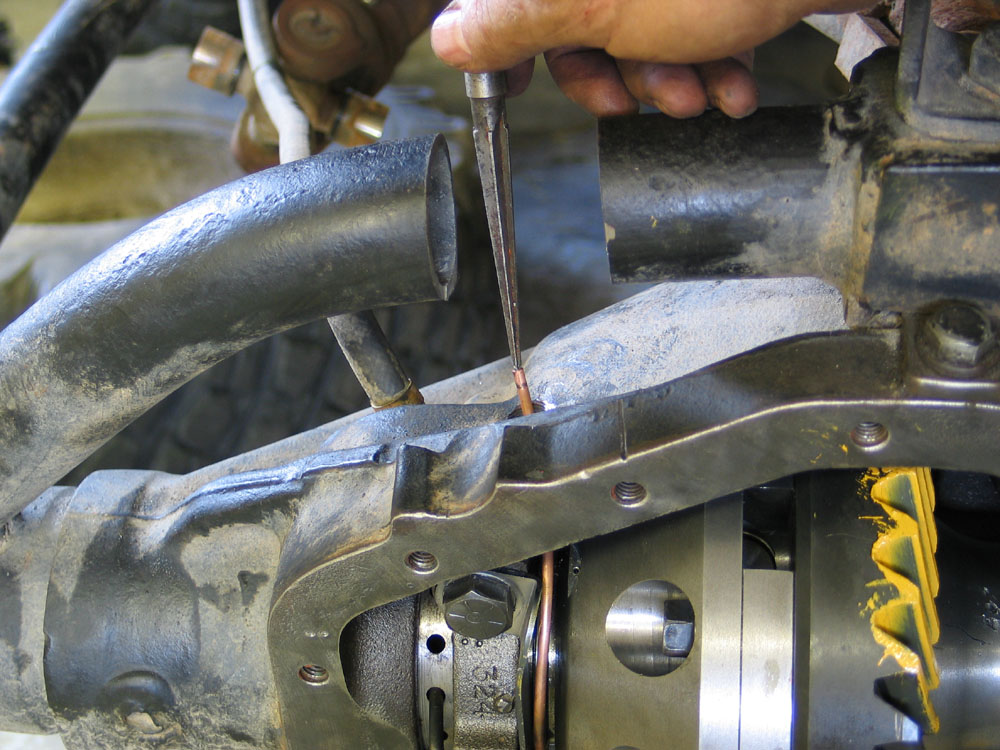
With the hole drilled, tap it with the 1/4" NPT tap. Note that this picture really illustrates how NOT to tap a hole - as I'm using a ratchet to drive the tap - which tends to load the tap unevenly and risks either tapping the hole crooked or breaking the tap in the hole. The proper method is to use a two-handled tap driver. However, as you can see, I had to cut my axle truss out of the way which left me short on space and clearance for the proper tap handle. Fortunately the axle housing is not very hard and I managed to tap the hole perfectly well like this. If, however, you side load the tap and break it off in the hole - don't say I didn't warn you! |
||||||||||||||||||||||||||||||||||||||||||||||||||||||||||||||||||||||||||||||||||||||||||||||||||||||||||||||||||||||||||||||||||||||||||||||||||||||||||||||||||||||||||||||||||||||||||||||||||||||||||||||||||||||||||||||||||||||||||||||||||||||||||||||||||||||||||||||||||||||||||||||||||||||||||||||||||||||||||||||||||||||||||||||||||||||||||||||||||||||||||||||||||||||||||||||||||||||||||||||||||||||||||||||||||||
Installing ARB Into Housing |
|||||||||||||||||||||||||||||||||||||||||||||||||||||||||||||||||||||||||||||||||||||||||||||||||||||||||||||||||||||||||||||||||||||||||||||||||||||||||||||||||||||||||||||||||||||||||||||||||||||||||||||||||||||||||||||||||||||||||||||||||||||||||||||||||||||||||||||||||||||||||||||||||||||||||||||||||||||||||||||||||||||||||||||||||||||||||||||||||||||||||||||||||||||||||||||||||||||||||||||||||||||||||||||||||||||
 |
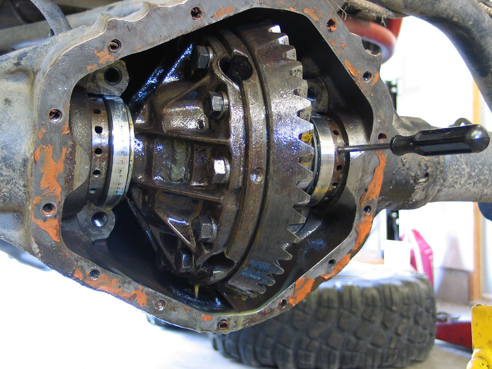
Now that the locker is assembled and the air port is tapped, it's time to install the locker. Ensuring the carrier bearing cups are on the carrier bearings, carefully place the locker in the axle housing. A helper is extremely useful at this stage, as the locker is heavy, and you have to be careful not to damage that copper seal housing tube. Install the carrier bearing caps in their original positions and tighten them until just snug. |
||||||||||||||||||||||||||||||||||||||||||||||||||||||||||||||||||||||||||||||||||||||||||||||||||||||||||||||||||||||||||||||||||||||||||||||||||||||||||||||||||||||||||||||||||||||||||||||||||||||||||||||||||||||||||||||||||||||||||||||||||||||||||||||||||||||||||||||||||||||||||||||||||||||||||||||||||||||||||||||||||||||||||||||||||||||||||||||||||||||||||||||||||||||||||||||||||||||||||||||||||||||||||||||||||||
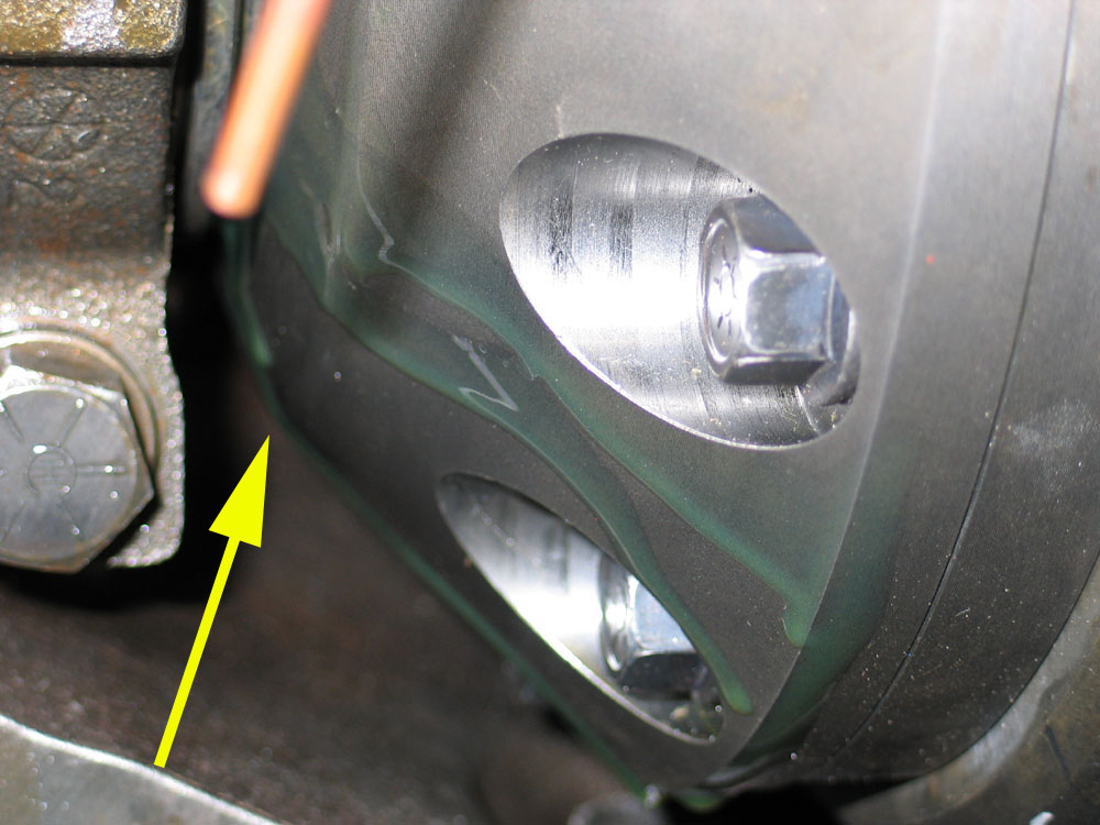 |
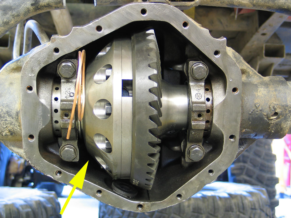
With the ARB installed, you must check for adequate clearance inside the housing. There must be no place where there is less than 1/16" clearance between any part of the ARB and the axle housing. Using a feeler gauge if necessary, check for the required clearance as you rotate the ARB by hand. The most probable location where there might be a lack of clearance is the area between the ARB and one of the ribs inside the housing, on the lower left, just to the right of the bearing cap bolt. This area is indicated in this pic and the one above by the yellow arrow. If there is insufficient clearance, you will have to remove the ARB and the pinion and grind or file the axle housing to gain the required clearance. After any grinding or filing - be sure to thoroughly clean the axle housing, removing all grinding dust and other particles, then re-install the pinion and ARB. |
||||||||||||||||||||||||||||||||||||||||||||||||||||||||||||||||||||||||||||||||||||||||||||||||||||||||||||||||||||||||||||||||||||||||||||||||||||||||||||||||||||||||||||||||||||||||||||||||||||||||||||||||||||||||||||||||||||||||||||||||||||||||||||||||||||||||||||||||||||||||||||||||||||||||||||||||||||||||||||||||||||||||||||||||||||||||||||||||||||||||||||||||||||||||||||||||||||||||||||||||||||||||||||||||||||
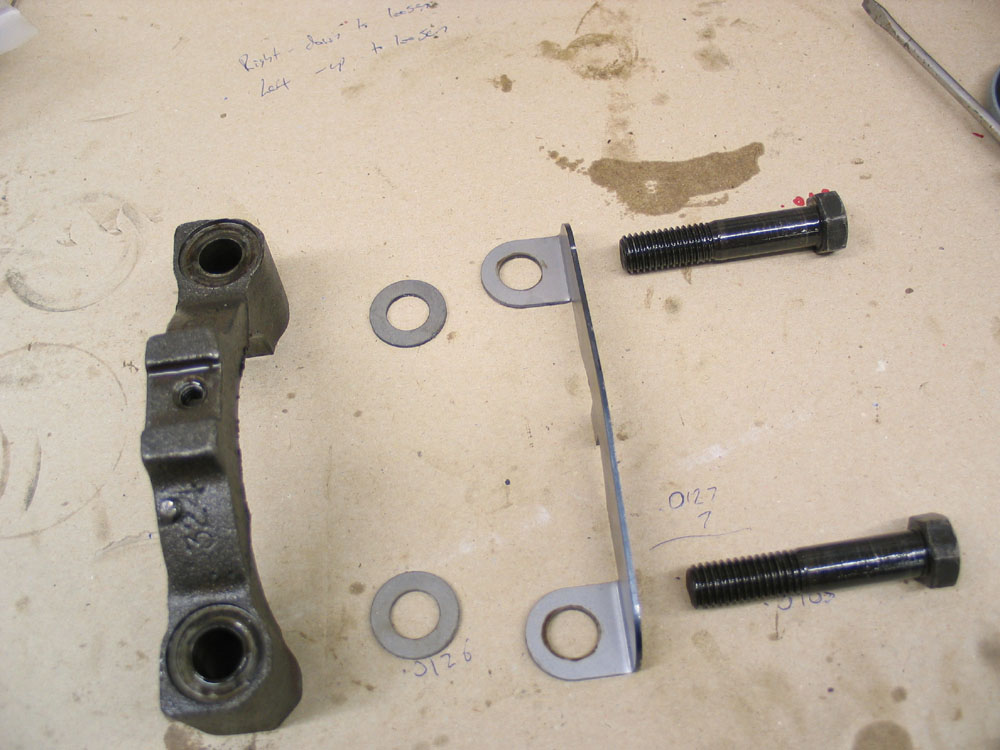 |
The next step is to install the seal housing bracket. This bracket is installed on top of the left side carrier bearing cap and keeps the seal housing from spinning with the locker which would breaking the seal housing tube. With the ARB in place in the axle housing, snug up the adjusting nuts so that it cannot fall from the housing. Remove the left side carrier bearing cap and discard the lock washers. This is because the seal housing bracket and washers will consume the thickness normally consumed by the lock washers. If the lock washers were also left in place, the cap bolts would not achieve proper and full thread engagement. You will replace the locking action of the washers by using thread locking compound later in the final assembly (NOT now). This picture shows the arrangement of the left bearing cap, washers, bracket, and bolts. The washers go between the the bracket and the bearing cap. |
||||||||||||||||||||||||||||||||||||||||||||||||||||||||||||||||||||||||||||||||||||||||||||||||||||||||||||||||||||||||||||||||||||||||||||||||||||||||||||||||||||||||||||||||||||||||||||||||||||||||||||||||||||||||||||||||||||||||||||||||||||||||||||||||||||||||||||||||||||||||||||||||||||||||||||||||||||||||||||||||||||||||||||||||||||||||||||||||||||||||||||||||||||||||||||||||||||||||||||||||||||||||||||||||||||
 |
The assembled bracket and bearing cap looks like this. | ||||||||||||||||||||||||||||||||||||||||||||||||||||||||||||||||||||||||||||||||||||||||||||||||||||||||||||||||||||||||||||||||||||||||||||||||||||||||||||||||||||||||||||||||||||||||||||||||||||||||||||||||||||||||||||||||||||||||||||||||||||||||||||||||||||||||||||||||||||||||||||||||||||||||||||||||||||||||||||||||||||||||||||||||||||||||||||||||||||||||||||||||||||||||||||||||||||||||||||||||||||||||||||||||||||
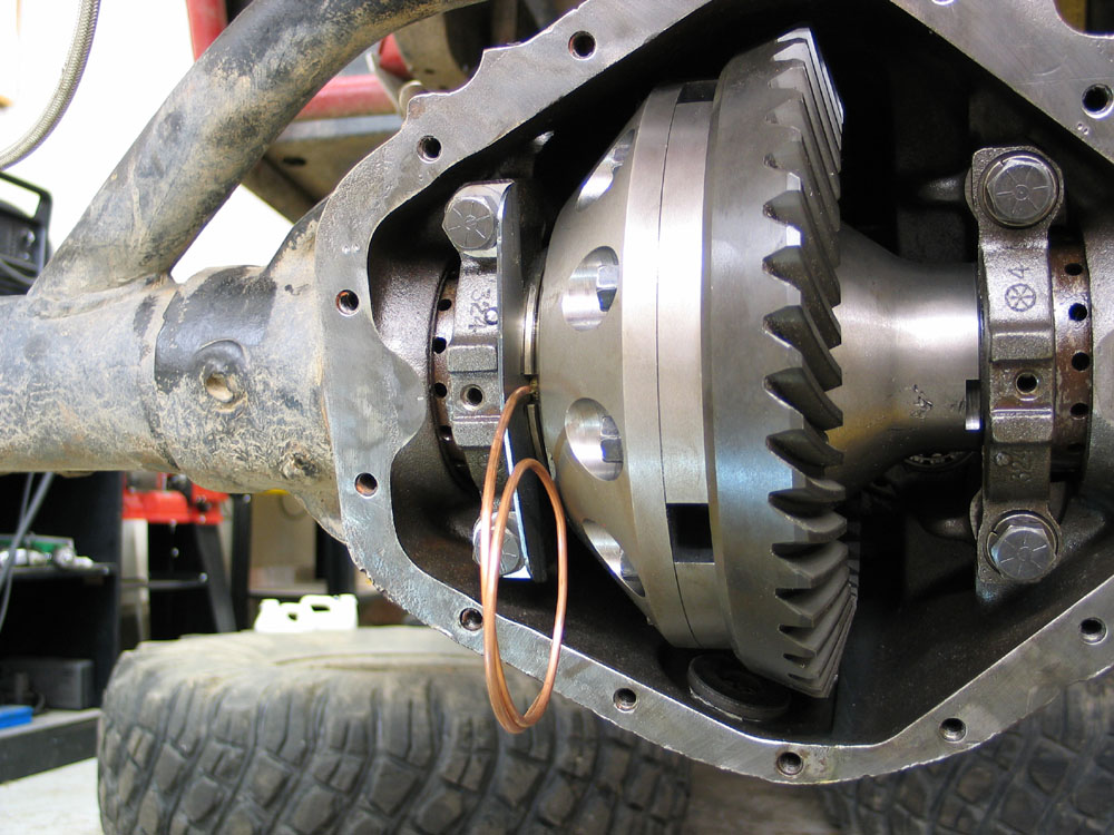 |
With the ARB correctly in place and fully seated, rotate the seal housing on the seal housing running surface until the seal housing tube sticks straight out of the housing like this. | ||||||||||||||||||||||||||||||||||||||||||||||||||||||||||||||||||||||||||||||||||||||||||||||||||||||||||||||||||||||||||||||||||||||||||||||||||||||||||||||||||||||||||||||||||||||||||||||||||||||||||||||||||||||||||||||||||||||||||||||||||||||||||||||||||||||||||||||||||||||||||||||||||||||||||||||||||||||||||||||||||||||||||||||||||||||||||||||||||||||||||||||||||||||||||||||||||||||||||||||||||||||||||||||||||||
 |
Then install the washers and seal housing bracket. Ensure the tab on the bracket engages the slot in the seal housing. Re-install the bearing cap bolts and tighten them until just snug. |
||||||||||||||||||||||||||||||||||||||||||||||||||||||||||||||||||||||||||||||||||||||||||||||||||||||||||||||||||||||||||||||||||||||||||||||||||||||||||||||||||||||||||||||||||||||||||||||||||||||||||||||||||||||||||||||||||||||||||||||||||||||||||||||||||||||||||||||||||||||||||||||||||||||||||||||||||||||||||||||||||||||||||||||||||||||||||||||||||||||||||||||||||||||||||||||||||||||||||||||||||||||||||||||||||||
 |
Close-up of the tab engaged in the slot. | ||||||||||||||||||||||||||||||||||||||||||||||||||||||||||||||||||||||||||||||||||||||||||||||||||||||||||||||||||||||||||||||||||||||||||||||||||||||||||||||||||||||||||||||||||||||||||||||||||||||||||||||||||||||||||||||||||||||||||||||||||||||||||||||||||||||||||||||||||||||||||||||||||||||||||||||||||||||||||||||||||||||||||||||||||||||||||||||||||||||||||||||||||||||||||||||||||||||||||||||||||||||||||||||||||||
Setting Backlash and Carrier Preload |
|||||||||||||||||||||||||||||||||||||||||||||||||||||||||||||||||||||||||||||||||||||||||||||||||||||||||||||||||||||||||||||||||||||||||||||||||||||||||||||||||||||||||||||||||||||||||||||||||||||||||||||||||||||||||||||||||||||||||||||||||||||||||||||||||||||||||||||||||||||||||||||||||||||||||||||||||||||||||||||||||||||||||||||||||||||||||||||||||||||||||||||||||||||||||||||||||||||||||||||||||||||||||||||||||||||
 |
Loosen right-side adjusting nut and tighten left-side adjusting nut until the ring gear contacts the pinion without binding. This is zero backlash. Back off left-side adjusting nut approximately two slots. Install left side adjusting nut lock, washer and bolt. Tighten bolt to 20 ft/lbs. Tighten right-side adjusting nut until ARB is forced into solid contact with left-side adjusting nut. Loosen right-side adjusting nut until it is free from bearing contact, then re-tighten until contact is re-established. Now tighten right-side adjusting nut two slots if carrier bearings are reused or three slots if carrier bearings are new. Install adjusting nut lock, washer, and bolt to right-side bearing cap. Tighten bolt to 20 ft/lbs. Tighten all bearing cap bolts to 135 ft/lbs. |
||||||||||||||||||||||||||||||||||||||||||||||||||||||||||||||||||||||||||||||||||||||||||||||||||||||||||||||||||||||||||||||||||||||||||||||||||||||||||||||||||||||||||||||||||||||||||||||||||||||||||||||||||||||||||||||||||||||||||||||||||||||||||||||||||||||||||||||||||||||||||||||||||||||||||||||||||||||||||||||||||||||||||||||||||||||||||||||||||||||||||||||||||||||||||||||||||||||||||||||||||||||||||||||||||||
The carrier bearings are now properly preloaded. If, to set backlash, the adjusting nuts must be adjusted after this step, make sure the preload remains the same. That is, if one adjusting nut is loosened, the other must be tightened an equal amount to maintain carrier bearing preload. Backlash should now be checked at a minimum of two different places on the ring gear. The dedicated will check backlash in four equally spaced places, and the truly devout will measure the axial run-out of the ring-gear, mark the high, low, and average spots, and use those spots to measure backlash. |
|||||||||||||||||||||||||||||||||||||||||||||||||||||||||||||||||||||||||||||||||||||||||||||||||||||||||||||||||||||||||||||||||||||||||||||||||||||||||||||||||||||||||||||||||||||||||||||||||||||||||||||||||||||||||||||||||||||||||||||||||||||||||||||||||||||||||||||||||||||||||||||||||||||||||||||||||||||||||||||||||||||||||||||||||||||||||||||||||||||||||||||||||||||||||||||||||||||||||||||||||||||||||||||||||||||
 |
Whichever method you choose, read the backlash as follows:
Backlash should be between .003" - .012", with .005"-.008" preferred. |
||||||||||||||||||||||||||||||||||||||||||||||||||||||||||||||||||||||||||||||||||||||||||||||||||||||||||||||||||||||||||||||||||||||||||||||||||||||||||||||||||||||||||||||||||||||||||||||||||||||||||||||||||||||||||||||||||||||||||||||||||||||||||||||||||||||||||||||||||||||||||||||||||||||||||||||||||||||||||||||||||||||||||||||||||||||||||||||||||||||||||||||||||||||||||||||||||||||||||||||||||||||||||||||||||||
If backlash is not within spec, adjustments are made with the adjusting nuts as follows:
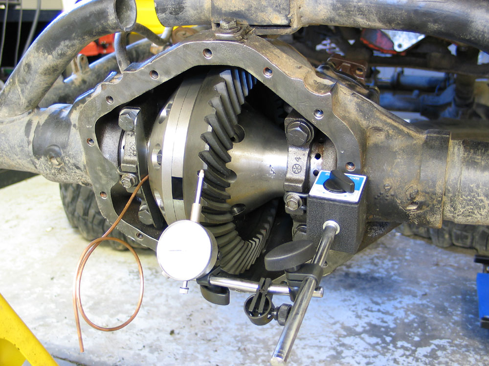
Once backlash has been set, remove the left-side bearing cap bolts, apply thread-locking compound to the threads, re-install the bolts and tighten to 135 ft/lbs. Checking the Contact PatternAt this stage, if all has gone well, and if you haven't changed the gears or replaced the pinion bearings, you shouldn't have to re-adjust the pinion depth. However, I recommend always checking the gear contact pattern just to be sure. |
|||||||||||||||||||||||||||||||||||||||||||||||||||||||||||||||||||||||||||||||||||||||||||||||||||||||||||||||||||||||||||||||||||||||||||||||||||||||||||||||||||||||||||||||||||||||||||||||||||||||||||||||||||||||||||||||||||||||||||||||||||||||||||||||||||||||||||||||||||||||||||||||||||||||||||||||||||||||||||||||||||||||||||||||||||||||||||||||||||||||||||||||||||||||||||||||||||||||||||||||||||||||||||||||||||||
 |
To check the contact pattern, proceed as follows: 1. Clean ring-gear teeth and wipe any oil out of the housing. |
||||||||||||||||||||||||||||||||||||||||||||||||||||||||||||||||||||||||||||||||||||||||||||||||||||||||||||||||||||||||||||||||||||||||||||||||||||||||||||||||||||||||||||||||||||||||||||||||||||||||||||||||||||||||||||||||||||||||||||||||||||||||||||||||||||||||||||||||||||||||||||||||||||||||||||||||||||||||||||||||||||||||||||||||||||||||||||||||||||||||||||||||||||||||||||||||||||||||||||||||||||||||||||||||||||
 |
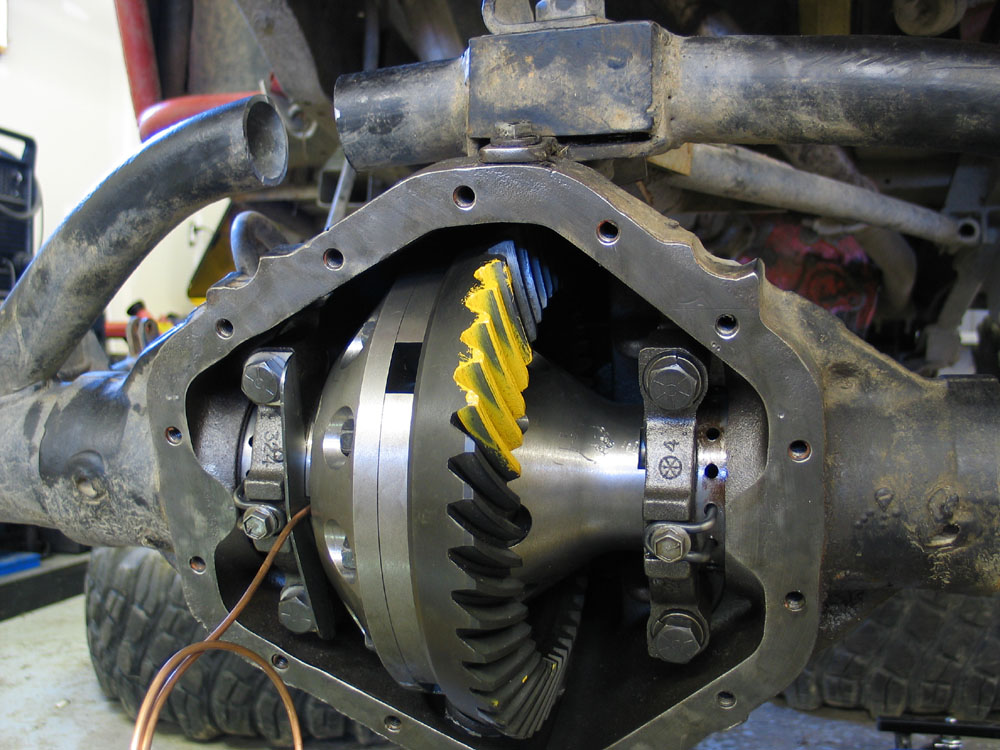
5. With the load on the gears in place, rotate the pinion two or three times in each direction through the marking compound. Excessive turning of the ring gear is not advisable. 6. Observe and record whether the pattern is towards the top or towards the root of the ring-gear teeth. Also note whether contact is at the heel or toe of the teeth. |
||||||||||||||||||||||||||||||||||||||||||||||||||||||||||||||||||||||||||||||||||||||||||||||||||||||||||||||||||||||||||||||||||||||||||||||||||||||||||||||||||||||||||||||||||||||||||||||||||||||||||||||||||||||||||||||||||||||||||||||||||||||||||||||||||||||||||||||||||||||||||||||||||||||||||||||||||||||||||||||||||||||||||||||||||||||||||||||||||||||||||||||||||||||||||||||||||||||||||||||||||||||||||||||||||||
Drive-side contact pattern interpretation |
7. You should see a pattern that is centred between the heel and toe and also between the top and root of the tooth, as shown in the centre diagram of the pic at left. There should be some clearance between the pattern and the top of the tooth. On the coast-side the pattern may be slightly towards the toe. The pattern should also be broad and diffuse, without sharp edges. If the pattern is found to be unacceptable, refer to the 14-Bolt Gear Setup article for instructions on how to set pinion depth. |
||||||||||||||||||||||||||||||||||||||||||||||||||||||||||||||||||||||||||||||||||||||||||||||||||||||||||||||||||||||||||||||||||||||||||||||||||||||||||||||||||||||||||||||||||||||||||||||||||||||||||||||||||||||||||||||||||||||||||||||||||||||||||||||||||||||||||||||||||||||||||||||||||||||||||||||||||||||||||||||||||||||||||||||||||||||||||||||||||||||||||||||||||||||||||||||||||||||||||||||||||||||||||||||||||||
Routing the Copper Seal Housing Tube |
|||||||||||||||||||||||||||||||||||||||||||||||||||||||||||||||||||||||||||||||||||||||||||||||||||||||||||||||||||||||||||||||||||||||||||||||||||||||||||||||||||||||||||||||||||||||||||||||||||||||||||||||||||||||||||||||||||||||||||||||||||||||||||||||||||||||||||||||||||||||||||||||||||||||||||||||||||||||||||||||||||||||||||||||||||||||||||||||||||||||||||||||||||||||||||||||||||||||||||||||||||||||||||||||||||||
 |
The next step is to route the seal housing tube. Using only your hands, carefully bend the seal housing tube so that it runs closely beside the seal housing bracket and through the hole you tapped in the housing. Keep the bends smooth, and handle the tube carefully to avoid damaging it. Make sure the tube doesn't contact the seal housing bracket or any part of the axle housing, otherwise shock and vibration may wear the tube and eventually cause an air leak. |
||||||||||||||||||||||||||||||||||||||||||||||||||||||||||||||||||||||||||||||||||||||||||||||||||||||||||||||||||||||||||||||||||||||||||||||||||||||||||||||||||||||||||||||||||||||||||||||||||||||||||||||||||||||||||||||||||||||||||||||||||||||||||||||||||||||||||||||||||||||||||||||||||||||||||||||||||||||||||||||||||||||||||||||||||||||||||||||||||||||||||||||||||||||||||||||||||||||||||||||||||||||||||||||||||||
 |
It should look like this when you are finished. | ||||||||||||||||||||||||||||||||||||||||||||||||||||||||||||||||||||||||||||||||||||||||||||||||||||||||||||||||||||||||||||||||||||||||||||||||||||||||||||||||||||||||||||||||||||||||||||||||||||||||||||||||||||||||||||||||||||||||||||||||||||||||||||||||||||||||||||||||||||||||||||||||||||||||||||||||||||||||||||||||||||||||||||||||||||||||||||||||||||||||||||||||||||||||||||||||||||||||||||||||||||||||||||||||||||
Finishing the Air Line Connection |
|||||||||||||||||||||||||||||||||||||||||||||||||||||||||||||||||||||||||||||||||||||||||||||||||||||||||||||||||||||||||||||||||||||||||||||||||||||||||||||||||||||||||||||||||||||||||||||||||||||||||||||||||||||||||||||||||||||||||||||||||||||||||||||||||||||||||||||||||||||||||||||||||||||||||||||||||||||||||||||||||||||||||||||||||||||||||||||||||||||||||||||||||||||||||||||||||||||||||||||||||||||||||||||||||||||
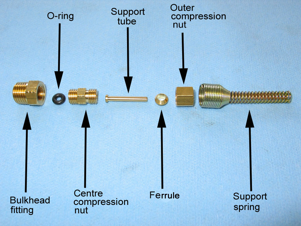 |
The final step in the installation of the locker is to install the bulkhead fitting in the axle housing and connect the seal housing tube to the blue nylon air line. The picture at left shows the parts involved, laid out in the orientation in which they are assembled. |
||||||||||||||||||||||||||||||||||||||||||||||||||||||||||||||||||||||||||||||||||||||||||||||||||||||||||||||||||||||||||||||||||||||||||||||||||||||||||||||||||||||||||||||||||||||||||||||||||||||||||||||||||||||||||||||||||||||||||||||||||||||||||||||||||||||||||||||||||||||||||||||||||||||||||||||||||||||||||||||||||||||||||||||||||||||||||||||||||||||||||||||||||||||||||||||||||||||||||||||||||||||||||||||||||||
 |
Cut off the seal housing tube with a mini brake-line tubing cutter; leaving 5/16" protruding above the housing. Be careful not to create any metal filings or allow any debris to fall into the tubing. | ||||||||||||||||||||||||||||||||||||||||||||||||||||||||||||||||||||||||||||||||||||||||||||||||||||||||||||||||||||||||||||||||||||||||||||||||||||||||||||||||||||||||||||||||||||||||||||||||||||||||||||||||||||||||||||||||||||||||||||||||||||||||||||||||||||||||||||||||||||||||||||||||||||||||||||||||||||||||||||||||||||||||||||||||||||||||||||||||||||||||||||||||||||||||||||||||||||||||||||||||||||||||||||||||||||
 |
Depending on the cut you get from your tubing cutter, you may find that you need to very carefully ream the cut-end of the tube. Again, be very careful not to let any filings fall inside the tube. | ||||||||||||||||||||||||||||||||||||||||||||||||||||||||||||||||||||||||||||||||||||||||||||||||||||||||||||||||||||||||||||||||||||||||||||||||||||||||||||||||||||||||||||||||||||||||||||||||||||||||||||||||||||||||||||||||||||||||||||||||||||||||||||||||||||||||||||||||||||||||||||||||||||||||||||||||||||||||||||||||||||||||||||||||||||||||||||||||||||||||||||||||||||||||||||||||||||||||||||||||||||||||||||||||||||
 |
Once it is carefully cut off, you should be left with 5/16" of copper tubing protruding above the housing. | ||||||||||||||||||||||||||||||||||||||||||||||||||||||||||||||||||||||||||||||||||||||||||||||||||||||||||||||||||||||||||||||||||||||||||||||||||||||||||||||||||||||||||||||||||||||||||||||||||||||||||||||||||||||||||||||||||||||||||||||||||||||||||||||||||||||||||||||||||||||||||||||||||||||||||||||||||||||||||||||||||||||||||||||||||||||||||||||||||||||||||||||||||||||||||||||||||||||||||||||||||||||||||||||||||||
 |
Wrap the threads of the bulkhead fitting with Teflon thread-sealant tape, place it over the tube, and tighten it carefully into the housing. | ||||||||||||||||||||||||||||||||||||||||||||||||||||||||||||||||||||||||||||||||||||||||||||||||||||||||||||||||||||||||||||||||||||||||||||||||||||||||||||||||||||||||||||||||||||||||||||||||||||||||||||||||||||||||||||||||||||||||||||||||||||||||||||||||||||||||||||||||||||||||||||||||||||||||||||||||||||||||||||||||||||||||||||||||||||||||||||||||||||||||||||||||||||||||||||||||||||||||||||||||||||||||||||||||||||
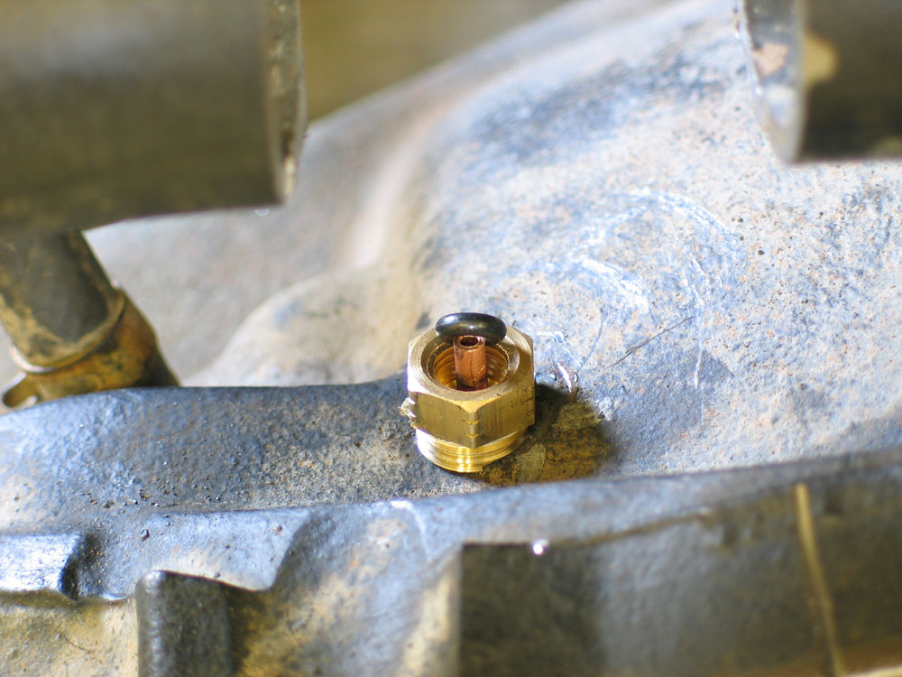 |
Carefully install the small O-ring over the end of the tube and press it down into the bulkhead fitting. A small blunt pic or screwdriver can be useful here - but be careful not to cut or nick the O-ring | ||||||||||||||||||||||||||||||||||||||||||||||||||||||||||||||||||||||||||||||||||||||||||||||||||||||||||||||||||||||||||||||||||||||||||||||||||||||||||||||||||||||||||||||||||||||||||||||||||||||||||||||||||||||||||||||||||||||||||||||||||||||||||||||||||||||||||||||||||||||||||||||||||||||||||||||||||||||||||||||||||||||||||||||||||||||||||||||||||||||||||||||||||||||||||||||||||||||||||||||||||||||||||||||||||||
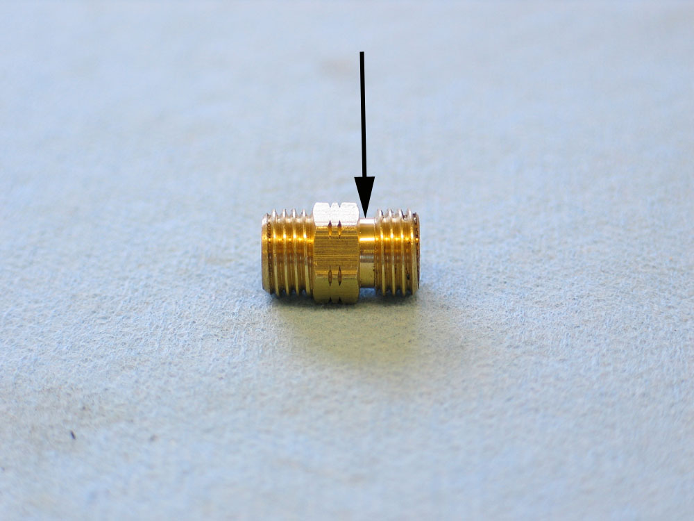 |
The next piece to install is the centre compression nut. You must take care to insert the correct end into the compression fitting, as that end has been machined to seal against the O-ring You can physically install it the wrong way round, as the threads are the same,but it will leak if you do. The end that goes into the compression fitting is the end that has the smooth area between the nut and the threads - indicted by the black arrow in the pic. |
||||||||||||||||||||||||||||||||||||||||||||||||||||||||||||||||||||||||||||||||||||||||||||||||||||||||||||||||||||||||||||||||||||||||||||||||||||||||||||||||||||||||||||||||||||||||||||||||||||||||||||||||||||||||||||||||||||||||||||||||||||||||||||||||||||||||||||||||||||||||||||||||||||||||||||||||||||||||||||||||||||||||||||||||||||||||||||||||||||||||||||||||||||||||||||||||||||||||||||||||||||||||||||||||||||
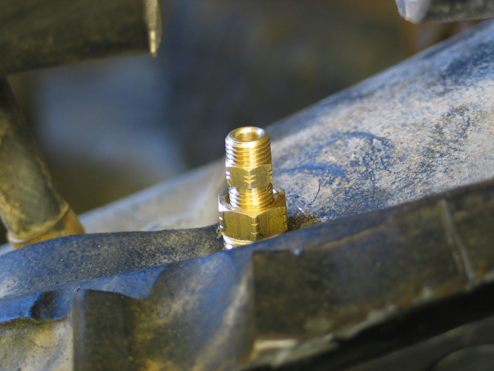 |
Support the copper seal housing tube from inside the diff by holding it with one hand. Insert the centre compression nut over the end of the tube and into the bulkhead fitting, then lightly tighten it. Do not over tighten the centre compression nut as this will damage the O-ring, the seal housing tube, or the threads of the centre compression nut. Excessive tightening is not required for the centre compression nut to form a good seal around the tube and with the O-ring Make sure the seal housing tube is all the way into the centre compression nut while you are tightening it into the bulkhead fitting. |
||||||||||||||||||||||||||||||||||||||||||||||||||||||||||||||||||||||||||||||||||||||||||||||||||||||||||||||||||||||||||||||||||||||||||||||||||||||||||||||||||||||||||||||||||||||||||||||||||||||||||||||||||||||||||||||||||||||||||||||||||||||||||||||||||||||||||||||||||||||||||||||||||||||||||||||||||||||||||||||||||||||||||||||||||||||||||||||||||||||||||||||||||||||||||||||||||||||||||||||||||||||||||||||||||||
 |
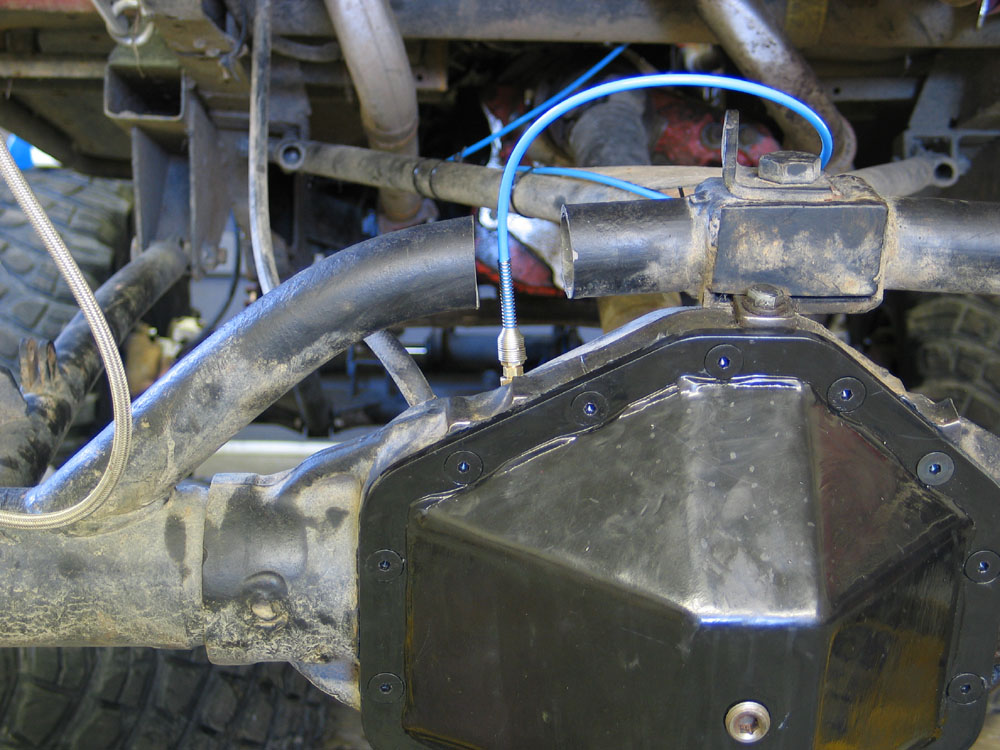
When finished, it should look like this. You are now finished installing the locker. All that remains is to run the air line and install the air source and switches. At this point you can re-install the diff cover, fill the axle with gear oil, and re-install the axles and wheels. |
||||||||||||||||||||||||||||||||||||||||||||||||||||||||||||||||||||||||||||||||||||||||||||||||||||||||||||||||||||||||||||||||||||||||||||||||||||||||||||||||||||||||||||||||||||||||||||||||||||||||||||||||||||||||||||||||||||||||||||||||||||||||||||||||||||||||||||||||||||||||||||||||||||||||||||||||||||||||||||||||||||||||||||||||||||||||||||||||||||||||||||||||||||||||||||||||||||||||||||||||||||||||||||||||||||
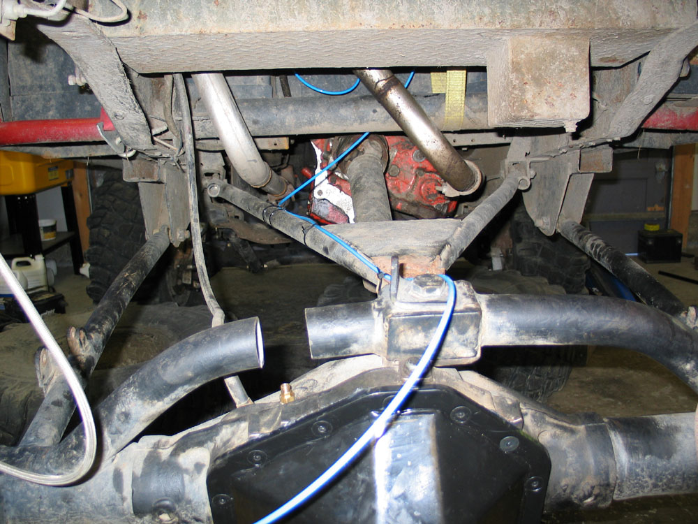 |
It is best to install the air line by starting from the switch or solenoid and routing it back to the axle before cutting it to length. This way you can check for length and clearance before committing to placement and length. Keep the air line away from sharp edges, abrasive surfaces, moving parts, and heat. Avoid tight bends and kinking the air line. Secure the air line with zip ties to avoid chafing due to vibration. Be sure to leave enough slack air line to allow for full suspension travel, but avoid leaving excessively large loops that can snag obstacles on the trail causing damage to the air line. |
||||||||||||||||||||||||||||||||||||||||||||||||||||||||||||||||||||||||||||||||||||||||||||||||||||||||||||||||||||||||||||||||||||||||||||||||||||||||||||||||||||||||||||||||||||||||||||||||||||||||||||||||||||||||||||||||||||||||||||||||||||||||||||||||||||||||||||||||||||||||||||||||||||||||||||||||||||||||||||||||||||||||||||||||||||||||||||||||||||||||||||||||||||||||||||||||||||||||||||||||||||||||||||||||||||
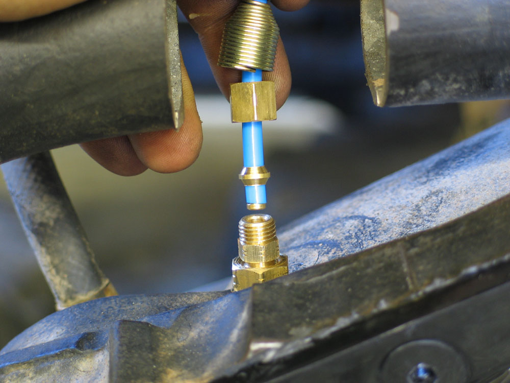 |
Once you are happy with the length and location of the air line, cut the axle end straight and square with a sharp utility knife. Slip the support spring (small end first) and outer compression nut over the air line. Slip the ferrule over the air line and push it up about 5mm from the end - as shown in the pic. Insert the support tube into the end of the air line. |
||||||||||||||||||||||||||||||||||||||||||||||||||||||||||||||||||||||||||||||||||||||||||||||||||||||||||||||||||||||||||||||||||||||||||||||||||||||||||||||||||||||||||||||||||||||||||||||||||||||||||||||||||||||||||||||||||||||||||||||||||||||||||||||||||||||||||||||||||||||||||||||||||||||||||||||||||||||||||||||||||||||||||||||||||||||||||||||||||||||||||||||||||||||||||||||||||||||||||||||||||||||||||||||||||||
 |
Push the air line, with support tube installed, all the way into the centre compression nut. Holding the air line in place, slide the ferrule into contact with the centre compression nut, and then carefully screw down the outer compression nut and tighten it. At this point, the end of the air line is permanently attached to the ferrule and the support tube. Using a pic or a small screwdriver, expand the lower coils of the support spring and install it over the end of the centre compression nut. |
||||||||||||||||||||||||||||||||||||||||||||||||||||||||||||||||||||||||||||||||||||||||||||||||||||||||||||||||||||||||||||||||||||||||||||||||||||||||||||||||||||||||||||||||||||||||||||||||||||||||||||||||||||||||||||||||||||||||||||||||||||||||||||||||||||||||||||||||||||||||||||||||||||||||||||||||||||||||||||||||||||||||||||||||||||||||||||||||||||||||||||||||||||||||||||||||||||||||||||||||||||||||||||||||||||
 |
Congratulations - you're finished! All that remains is to connect the air line to the air supply and install the switches. I have detailed that procedure in: ARB Install Part 2 - Supplying Air to the ARB |
||||||||||||||||||||||||||||||||||||||||||||||||||||||||||||||||||||||||||||||||||||||||||||||||||||||||||||||||||||||||||||||||||||||||||||||||||||||||||||||||||||||||||||||||||||||||||||||||||||||||||||||||||||||||||||||||||||||||||||||||||||||||||||||||||||||||||||||||||||||||||||||||||||||||||||||||||||||||||||||||||||||||||||||||||||||||||||||||||||||||||||||||||||||||||||||||||||||||||||||||||||||||||||||||||||
ARB FAQI wanted to add this extra section at the end of this article to address some of the misinformation regarding the ARB that I found floating around out there. Please note that these opinions and "answers' are mine alone and are not necessarily endorsed by ARB. Having said that - I am deeply grateful to Tim "The Tech Man" Lund of ARB USA for his patience answering my many questions during the research for this article. What are the advantages to a selectable locker?
There are many more, I'm sure, but they all boil down to ultimate flexibility. With a selectable locker you have the choice of when it is locked or unlocked. Is an ARB any less reliable than other lockers?No, not if it installed and maintained properly. Sure, there are more parts and installation is trickier - but this true of many other components you'd never consider inferior because of their complexity. EFI is more complex, has more parts, and is more difficult to install than a carb - but no one in their right mind would choose a carb over EFI because there are more parts in an EFI system. A coil-over 4-link suspension is more complex than leaf springs - but for extreme use, it's clearly the better choice. Heck - there are more parts and greater complexity in a car than a horse-drawn buggy - but you don't see people running the Rubicon on wagon wheels! But what about those who claim they prefer a simple automatic locker?Well, there is always a tendency for folks to defend whatever system they choose to run - it's normal and it's natural. But let me ask you this: how many folks running automatic lockers have also run an ARB? Better yet - how many folks have run automatic lockers, upgraded to an ARB selectable, and then decided to switch back because they liked the auto locker so much more? Not very many! Isn't the supplied blue plastic air line a weak link?Yes, and it's supposed to be. It is what is known as an "engineered weak link." Yes it is weak and easy to break, because it is supposed to be. This is so that, if you snag an air line, it'll break and can easily be repaired in the field with a splice or a new ferrule in a couple of minutes. However, if you run stronger air lines (like stainless steel or hydraulic hose) and you snag a line, the line may not break. Instead you end up pulling the fittings out of the axle or the compressor. This is much more difficult to fix. Having said that - proper routing of the air-line is critical and will go a long way to ensuring failure-free operation. Make sure you route it well, tie it down every 12" or less, and keep it away from heat, vibration, sharp edges, and the like. No two installations will be exactly the same - but common sense and a good plan will help. Routing it along-side flexible brake hoses is one good option. In terrain where there is a lot of brush, bushes, logs and other debris, abrasion damage to the line can be minimized by protecting it with a sleeve of vacuum hose or wiring loom - without loosing the desired weak-link feature. How can I patch a hole in my air line?Quite easily. The best way is to replace any damaged section with a new piece of line and some splice fittings. ARB supplies metric push-lock fittings for this purpose. In my experience, you can also splice a line with standard 3/16" compression fittings - the type that use a threaded body. a ferrule, and a compression nut. Since the ARB line is 5mm, which is slightly larger than 3/16", you may have to lightly sand the end of the air line with a piece of emery cloth or sand paper, to get the 3/16" ferrule to fit on - but once assembled it works quite well. Often, several varieties of air-line fittings can be found at heavy-duty truck parts suppliers or other outlets that cater to vehicles that use air brakes. In a pinch, successful field repairs of the air line have been accomplished using epoxy, steel putty, JB weld, vinyl tube and super glue, and even the ubiquitous duct tape! Where can I get replacement parts for my ARB?Parts and accessories are available direct from ARB or from any one of a large international network of retailers. ARB can be reached at (425) 264-1391 Will I / Why do I get gear oil coming up the air lines?You should not have gear oil being forced up the air supply line. If you do have this condition - it is an indication that there is some sort of problem. A properly installed and functioning ARB will run at any angle and not cause gear-oil to come up the air line. The most common causes of this problem are:
The easiest way to determine which problem is affecting you is to disengage the locker and drive normally for a week without using the locker. If you still get gear oil out the air line - a lack of sufficient axle housing venting is the likely cause. If you don't have any signs of oil after the week, engage and disengage the locker several times. If oil is now present, it indicates that the oil is travelling up the line when the locker is depressurized - meaning the seal housing O-rings are the likely culprit. What are the most important things to watch out for when installing an ARB?Care and cleanliness are obvious - as is reading the directions thoroughly first. In addition, special care should be taken to:
How many models require drilling of the bearing cap during installation?Few models require drilling of the bearing cap for the seal housing tube anymore. The Dana 60 is probably the only common model still requiring this step. What sizes are the O-rings used in the ARBs?They are all standard, common sizes - nothing custom. In order to order an O-ring you need to know two things - the size and the material. O-rings come in a variety of different materials, depending on their use. The two most common are Nitrile (Buna-N) and Viton. The following table illustrates some different O-ring materials and their properties. Note that in the "Material" column, where it says, for example "Standard: 70 Durometer Black" this indicates the standard hardness of the material (durometer is a reading of hardness - you may see it quoted by racers when referring to how hard or soft a tire's rubber compound is) and the standard colour of the O-ring
|
|||||||||||||||||||||||||||||||||||||||||||||||||||||||||||||||||||||||||||||||||||||||||||||||||||||||||||||||||||||||||||||||||||||||||||||||||||||||||||||||||||||||||||||||||||||||||||||||||||||||||||||||||||||||||||||||||||||||||||||||||||||||||||||||||||||||||||||||||||||||||||||||||||||||||||||||||||||||||||||||||||||||||||||||||||||||||||||||||||||||||||||||||||||||||||||||||||||||||||||||||||||||||||||||||||||
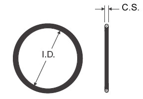 |
O-ring size is determined by the inside diameter (I.D.) and the cross section (C.S.) as shown in this diagram. | ||||||||||||||||||||||||||||||||||||||||||||||||||||||||||||||||||||||||||||||||||||||||||||||||||||||||||||||||||||||||||||||||||||||||||||||||||||||||||||||||||||||||||||||||||||||||||||||||||||||||||||||||||||||||||||||||||||||||||||||||||||||||||||||||||||||||||||||||||||||||||||||||||||||||||||||||||||||||||||||||||||||||||||||||||||||||||||||||||||||||||||||||||||||||||||||||||||||||||||||||||||||||||||||||||||
To make things easier when specifying an O-ring, there are two common international O-ring standards that can be used. The first is the AS568A standard. It consists of a "dash number" that allows both the ID and the CS to be called out by a single number. For example, an O-ring that is "dash 151" has an ID of 3" and a cross section of 3/32". The AS568A dash number doesn't tell us anything about the material though - so if we order by AS568A dash number, we still have to specify the material - for example: "I'm looking for a dash one fifty four in Nitrile". The other standard is the British Standard (BS). This is the most convenient standard, as any O-ring's BS number identifies not only the precise size but also the material. It does so by using a prefix equal to the AS568A dash number, coupled with a letter and two numbers that identify the material and the durometer (hardness) of the material. N denotes "Nitrile" and V denotes "Viton". For example, an O-ring that is BS 151N70 is an O-ring that has a 3" ID, a 3/32" cross section, and is made of Nitrile durometer 70. You can find the size of the O-rings required for your ARB from the following table. To use the table, you must know the ARB part number for your particular locker. If you don't know it, you can find it by looking in the North American ARB Application Catalogue or the International ARB Application Catalogue or by examining the ARB application lists that follows the O-ring table. ARB O-ring Table
ARB Applications - International
ARB Applications - North America
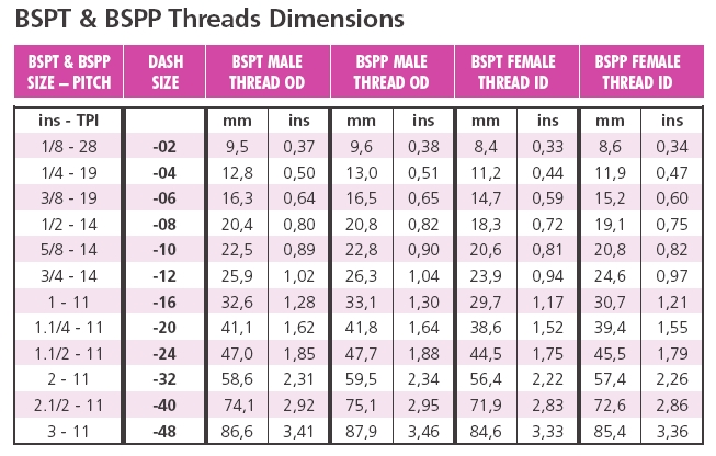
Why all the metric air line and fittings?Quite simply because ARB is an Australian-based global company. Most of the planet uses metric - Australia, Great Britain, Europe, Japan, Canada, South Africa, South America, etc. Some countries, like Canada, have both standard and metric fittings readily available. It seems that only in the USA are metric line and fittings hard to come by - although with increased globalization even this becomes less true as time passes - for example, there's not a car manufactured in the US today that doesn't use at least some metric fasteners. All this is, of course, not terribly helpful if you happen to live in a region where metric parts are hard to come by. If this is the case, you have several options: 1) Use the ARB supplied parts and source metric replacements directly from ARB or one of their distributors 2) Use the ARB supplied parts and the closest fitting standard parts if you need replacements - such as using 3/16" compression fittings with the 5mm air line or 3) Convert your system to standard (SAE & NPT) sized components (see below) What are the threads on the axle housing bulkhead fitting centre compression nut?3/8"-24 UNF What are the threads in the ARB solenoid? Can I use a 1/8 NPT fitting?1/8" BSPT (British Standard Pipe Tapered) BSP stands for British Standard Pipe, of which there are two types: parallel and tapered. BSPT is British Standard Pipe Tapered and BSPP is British Standard Pipe Parallel. Obviously one has parallel threads and the other, tapered threads. BSP threads are common in gas and pneumatics (indeed, you may see BSP threads referred to as "Gas" or "G", as in "that fitting is 1/8-G") BSPT threads are very similar to, but not exactly the same as NPT threads, as the following diagrams and charts illustrate: |
|||||||||||||||||||||||||||||||||||||||||||||||||||||||||||||||||||||||||||||||||||||||||||||||||||||||||||||||||||||||||||||||||||||||||||||||||||||||||||||||||||||||||||||||||||||||||||||||||||||||||||||||||||||||||||||||||||||||||||||||||||||||||||||||||||||||||||||||||||||||||||||||||||||||||||||||||||||||||||||||||||||||||||||||||||||||||||||||||||||||||||||||||||||||||||||||||||||||||||||||||||||||||||||||||||||
 |
 |
||||||||||||||||||||||||||||||||||||||||||||||||||||||||||||||||||||||||||||||||||||||||||||||||||||||||||||||||||||||||||||||||||||||||||||||||||||||||||||||||||||||||||||||||||||||||||||||||||||||||||||||||||||||||||||||||||||||||||||||||||||||||||||||||||||||||||||||||||||||||||||||||||||||||||||||||||||||||||||||||||||||||||||||||||||||||||||||||||||||||||||||||||||||||||||||||||||||||||||||||||||||||||||||||||||
 |
 |
||||||||||||||||||||||||||||||||||||||||||||||||||||||||||||||||||||||||||||||||||||||||||||||||||||||||||||||||||||||||||||||||||||||||||||||||||||||||||||||||||||||||||||||||||||||||||||||||||||||||||||||||||||||||||||||||||||||||||||||||||||||||||||||||||||||||||||||||||||||||||||||||||||||||||||||||||||||||||||||||||||||||||||||||||||||||||||||||||||||||||||||||||||||||||||||||||||||||||||||||||||||||||||||||||||
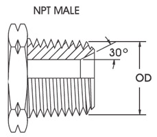
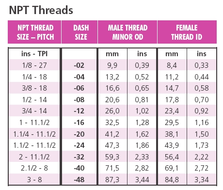
You can also see from the charts that 1/8 BSPT is 28 Thread Per Inch (TPI) while 1/8" NPT is 27 TPI. Many people have reported success screwing a 1/8" NPT male fitting into a 1/8" BSPT and achieving a leak free connection by using a lot of Teflon tape, plumbers dope, or thread locking compound. The better way to do it is to use a BSPT to NPT conversion fitting. These are available from good hydraulic or pneumatics suppliers. They are also available from auto parts suppliers often sold as gauge conversion fittings as many Japanese and European car engines will have 1/8" BSPT port for gauge sending units while many popular North American gauges have NPT sending units. What are the threads on... |
|||||||||||||||||||||||||||||||||||||||||||||||||||||||||||||||||||||||||||||||||||||||||||||||||||||||||||||||||||||||||||||||||||||||||||||||||||||||||||||||||||||||||||||||||||||||||||||||||||||||||||||||||||||||||||||||||||||||||||||||||||||||||||||||||||||||||||||||||||||||||||||||||||||||||||||||||||||||||||||||||||||||||||||||||||||||||||||||||||||||||||||||||||||||||||||||||||||||||||||||||||||||||||||||||||||
 |
Aw heck - here's a complete diagram: | ||||||||||||||||||||||||||||||||||||||||||||||||||||||||||||||||||||||||||||||||||||||||||||||||||||||||||||||||||||||||||||||||||||||||||||||||||||||||||||||||||||||||||||||||||||||||||||||||||||||||||||||||||||||||||||||||||||||||||||||||||||||||||||||||||||||||||||||||||||||||||||||||||||||||||||||||||||||||||||||||||||||||||||||||||||||||||||||||||||||||||||||||||||||||||||||||||||||||||||||||||||||||||||||||||||
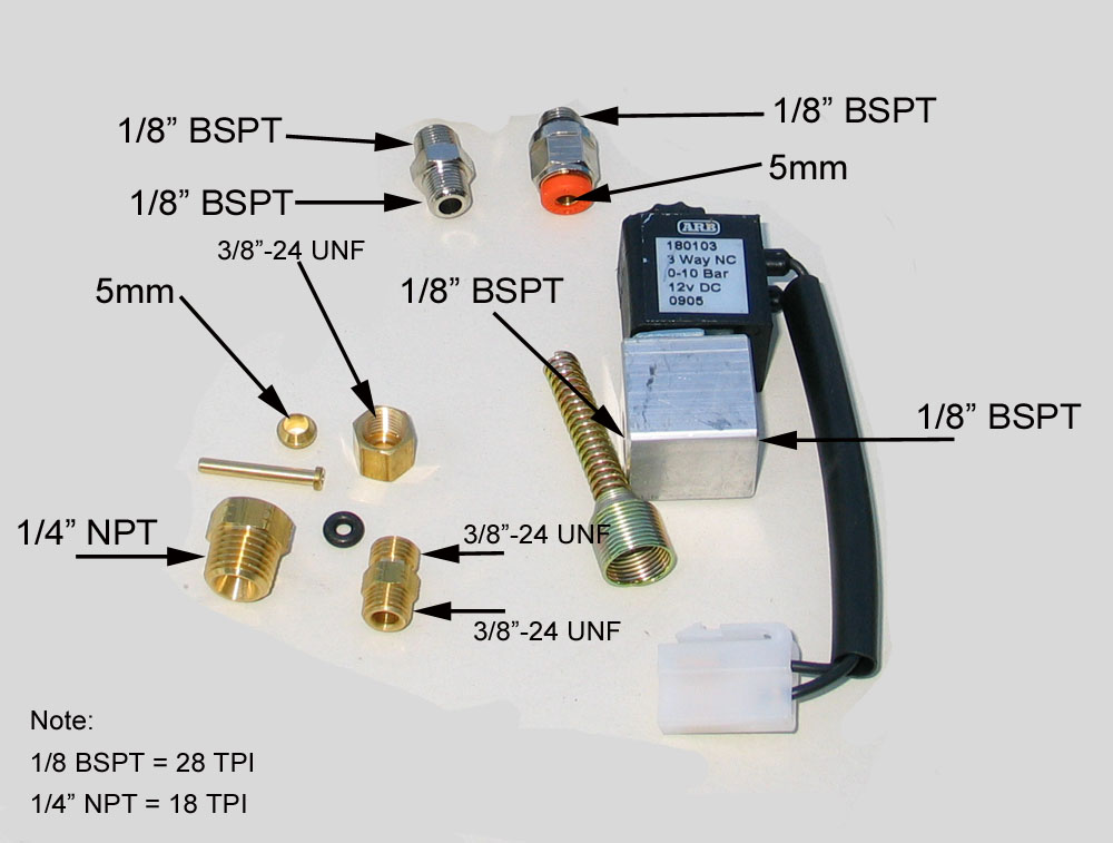
Can I convert my ARB to use SAE line and fittings instead of metric?Yes you can, and quite easily. The only metric parts of the system are the air line itself (5mm), and the ferrule and tube support at the bulkhead fitting (both sized for the 5mm air line). Everything else is standard size threads, except the ARB solenoids and the solenoid-air line fittings. The Solenoids have a female 1/8" BSPT thread, and the solenoid-air line fittings are male 1/8" BSPT one side and 5mm push-lock on the other side. If you are using the ARB supplied solenoids to activate your air locker(s), and desire an NPT system from end to end, you will need to convert your air line at the solenoid end, as well as at the axle housing bulkhead fitting end. If you are using some other air supply system, you simply need to run whatever size SAE air line you choose (e.g. 3/16" or 1/4") to the axle and convert only the axle housing bulkhead fitting end. Let's assume you want to run 1/4" air line and are using the ARB solenoids:
Of course, with the right conversion fittings and/or silver-soldering fittings to the ARB bulkhead fitting almost any combination is possible -for example you could convert to using all -AN fittings and air line if you so desired. Will breaking an axle shaft damage my ARB?It is possible, though much less likely than with automatic style lockers. Normally, when an axle shaft breaks with an ARB locker, if the locker is damaged, often just one of the end caps gets hogged out, which requires a relatively inexpensive repair (compared to replacing the entire locker). Is it true that ARB made some recent design changes to the internal seals to improve performance and reliability?Yes. The biggest change in recent times was to the internal seal. It has been changed from a O-ring or cup seal to a Bonded Piston Seal which is basically a rubber coated steel washer. The result is better cold weather performance and better sealing against excessive housing pressure. The other reason for a decline in the number of reports of air sealing issues is attributable to much improved installation procedures, installation instructions, and installer training. Can I use my ARB with an alternate air supply or only with an ARB compressor?You can use any supply of inert gas (air, CO2, or Nitrogen) that supplies clean, dry gas between 85 and 105 psi. People have successfully used CO2 "Power" tanks, on-board air compressors, and even small CO2 cartridges, such as those used with paint-ball equipment. Be advised that the ARB installation manual clearly states: "ARB cannot warrant your air locker(s) against damage caused as a result of using an alternate air supply. If you have any doubts as to the suitability of your air system to use in an air locker system, consult your ARB distributor.: Note that this DOES NOT say your ARB warranty is void if you use an alternate air source - just that if you damage your locker by using this alternate source the warranty won't cover it. Why does the factory ARB air supply installation include so much wiring?I believe the intent of the ARB supplied wiring and switches is to allow for a clean installation in a "factory like" vehicle. The system was designed so that the switches would easily integrate with a factory dash - complete with backlit switches etc. For those of us with rugged, dedicated trail buggies that have few comforts or amenities to begin with one can always forego some or all of the factory wiring and switches in favour of a "full pneumatic" system. How do I plumb my ARB for "full pneumatic" operation?See ARB Install Part 2 - Supplying Air to the ARB Why hasn't ARB ever offered a factory "all pneumatic" installation kit?Good question! What pressure do I need to supply to operate my ARB?Clean, dry air regulated to a minimum of 85psi and a maximum of 105 psi Will regulating the pressure to less than this make the seals/O-rings last longer?No, this is an urban legend. ARB air lockers are factory tested to well beyond the recommended operating pressure. You will not cause premature wear of component failure by supplying the air pressure as required by the ARB manual. Using the ARB wiring harness, why does my front locker only operate AFTER my rear is already engaged?It's a built in "safety system". If both switches were armed independently, it is conceivable that you could inadvertently engage the front locker while driving down the highway - resulting in a pretty serious loss of control and the impending doom that follows. Presumably they believe that if you inadvertently engage the rear locker, potential loss of control is less (though I'd have to argue with this. Having driven automatic lockers on the highway in snow and ice I can tell you that any sudden locker activation can be pretty scary at the least). The theory is that if you have to engage the rear locker before the first there is less chance of inadvertently engaging the front. How effective this system is in the real world I cannot say. In a dedicated hard-core trail rig it has its limitations though. Imagine what a pain it would be if your rear air line is broken or the rear axle is broken or any other of a myriad of reasons why you might want to engage the front locker and not the rear (cutting brakes, for example). Can I bypass this system?Yes - although you do so completely at your own risk and against the recommendation of ARB. The most common method is as follows: Unplug the yellow wire going into the centre terminal of switch #2. Run a tee from the red wire feeding into the centre terminal of switch #1 into the centre terminal of switch #2. Now when you engage the compressor switch you arm both switch #1 and switch #2. ConclusionIf you've read this far there's very little I can add at this point that isn't already apparent. The new 14-Bolt ARB, part # RD114, delivers ARB quality, legendary ARB customer service, and great performance. The pictures speak for themselves - if you have any doubt as to the quality of this unit - go back to the first series of pictures, enlarge them to full size, and examine them yourself. I can add that, once in your hands, the physical size and weight of the RD114 is even more impressive than the pictures. To complete the package, the ARB packaging, and especially the instructions, are quite simply the best of any product I have ever reviewed. The design of the ARB is unique and keeps all the working parts protected inside the diff cover. This design also means that the ARB is probably the most challenging and tricky locker there is to install. You have to be especially careful about installing the seal housing & O-rings, drilling and tapping the axle housing, installing the carrier bearings, handling the locker without damaging the copper seal housing tube, and running the plastic air line. However, with this article and ARB's excellent instructions, any competent wrench should have no difficulty. Immediately after installing the ARB, I took my rig on a 5-day, 1400km round-trip, wheeling adventure to the famous Paragon Adventure Park in Hazelton, PA. There I took on the toughest "red" trails I could find in the park, and while my rig suffered some severe carnage, including destroying the rear suspension, I never had a lick of trouble from my new ARB. It was reliable and trouble free the entire time, never failing to engage or disengage on my command. Not only that, but even in my dedicated, trail-only, rock-buggy it was a real treat to be able to lock or unlock the rear diff at will. Having lived with a spool for several years I found myself suddenly spoiled with the ability to make tighter turns, optimize my cutting brake performance, and even enjoy wheeling some of the easier trails with open diffs again. Best of all - ARB have all but eliminated any argument challenging the superiority of the mighty 14-Bolt. Go to >>> ARB Install Part 2 - Supplying Air to the ARB References:
|
|||||||||||||||||||||||||||||||||||||||||||||||||||||||||||||||||||||||||||||||||||||||||||||||||||||||||||||||||||||||||||||||||||||||||||||||||||||||||||||||||||||||||||||||||||||||||||||||||||||||||||||||||||||||||||||||||||||||||||||||||||||||||||||||||||||||||||||||||||||||||||||||||||||||||||||||||||||||||||||||||||||||||||||||||||||||||||||||||||||||||||||||||||||||||||||||||||||||||||||||||||||||||||||||||||||
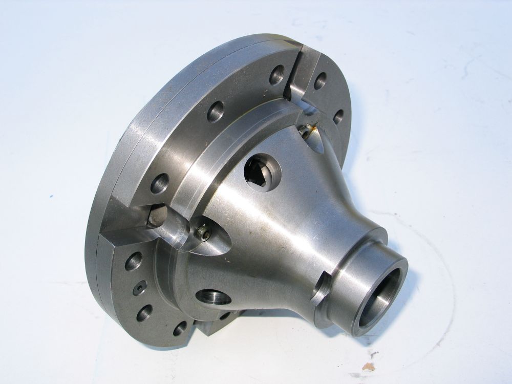


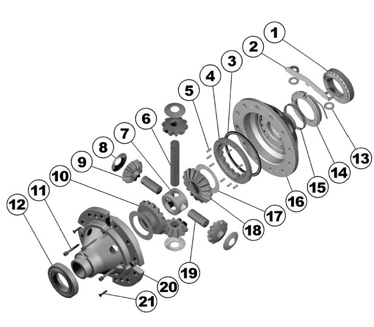
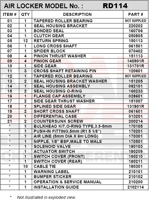
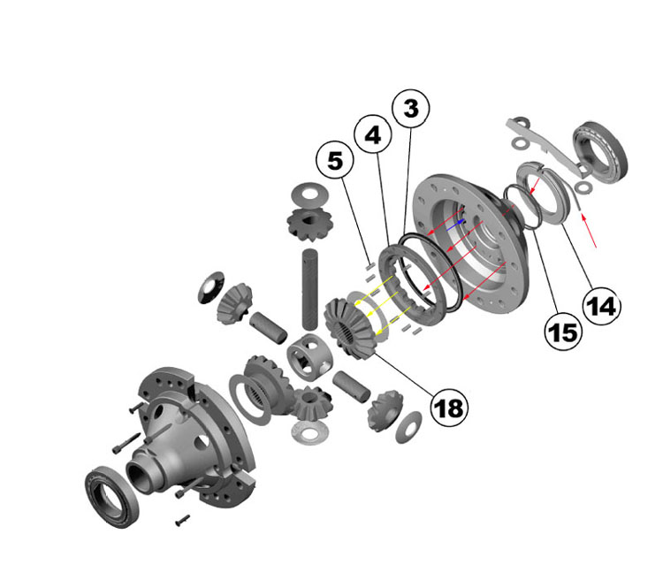

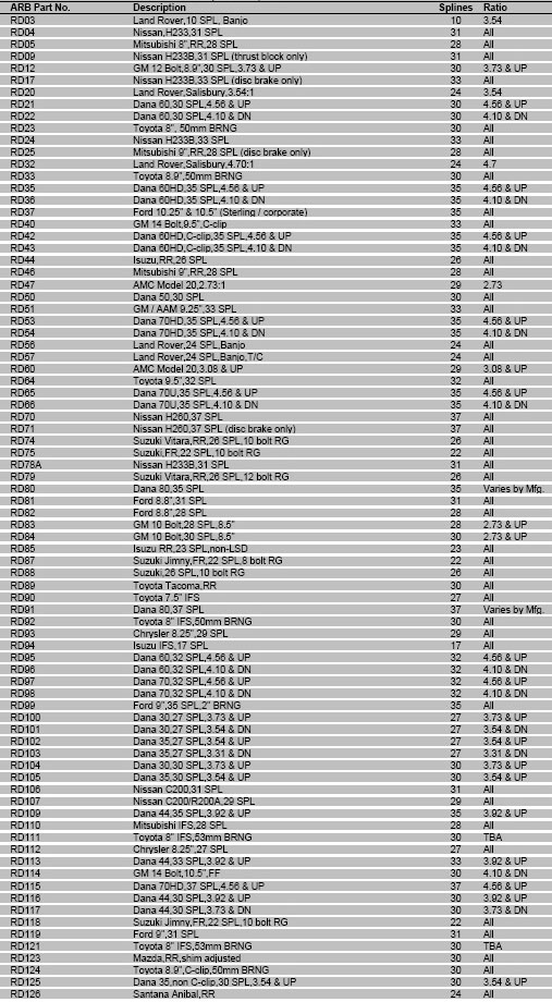
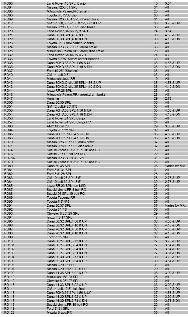
|
Sources: ARB USA 720 SW 34th St. |
|