 |
ARB Install - Air Supply & Compressor Review By Bill "BillaVista" Ansell |
Go to >>> ARB Install Part 1 - ARB 14-Bolt Air Locker Install I used to have oodles of air. At one point I had no less than three independent sources of air on my rig - an OBA engine-mounted compressor setup, a power-tank CO2 setup, and one of those cheap worthless parts-store 12v electric compressors taking up valuable space in the "trunk." My options for supplying my air lockers were seemingly limitless! However, a recent major re-design of the rig - I converted it from 2-seater to 4-seater without extending the wheelbase - robbed me of space and left me without any appropriate air supply for the air lockers. The new seats and fuel cell took up virtually all the space I had - no longer do I have room for the power tank or the electric compressor (no big loss on the latter - they really are useless - so don't ever be tempted to waste your money on one regardless of the sale price!). Not only that, but I also lost the space where I used to keep the tank that the OBA compressor filled. I still have the compressor mounted - without tank - and it works fine for filling tires - but all of a sudden I had no decent way to power the lockers. |
 |
Not only that but space, normally at a premium in a buggy, was now approaching an all-time, sellers market, real-estate boon, Donald Trump gettin' fatter, level! What I really needed was a compact, reliable, independent system for supplying the lockers. Something that didn't take up much space, could be mounted anywhere, and would reliably and independently power the lockers. Enter the new CKSA12 Compact Onboard Air Kit from ARB. It's exactly what I needed. Follow along as I detail the install and also explain the why's and wherefore's of a "full pneumatic" air locker activation system. Inside the Kit |
|
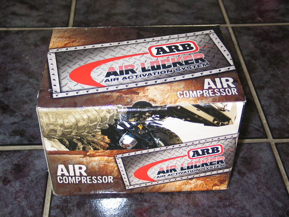 |
The kit comes in the typical top-quality packaging one comes to expect from ARB. |
 |
Inside are all the pieces required, including an excellent set of instructions and clearly labelled wiring harness. |
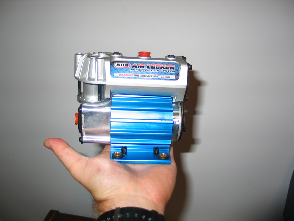 |
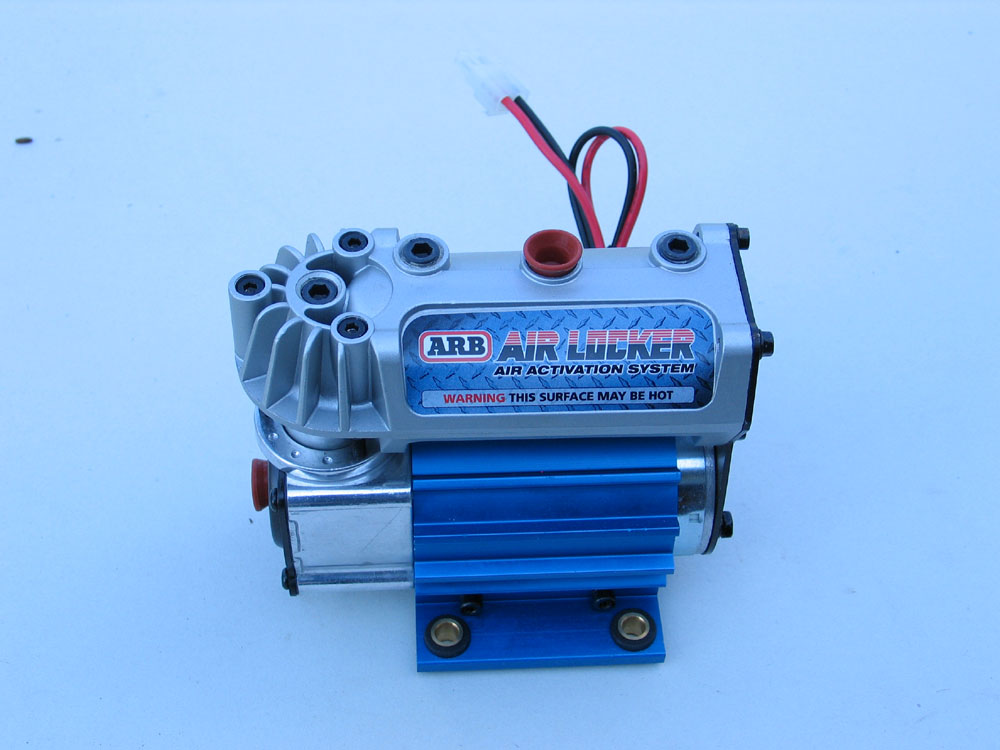
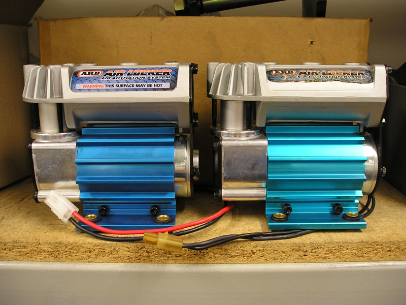
The compressor itself is extremely compact - perfect for squeezing into the tight space available in a buggy, and also easy to mount under the hood (or anywhere else) in more conventional rigs. |
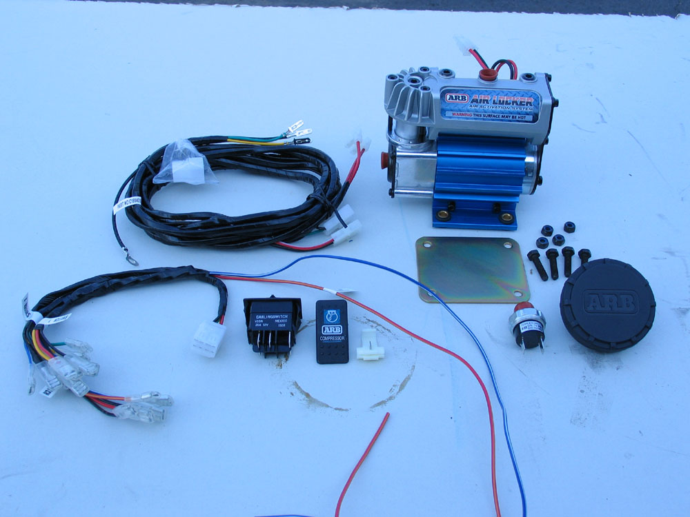 |
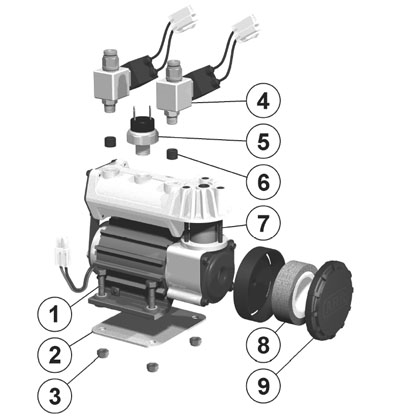
The kit contains (clockwise from top right) the compressor, mounting plate and hardware, air filter, pressure switch, dash-mount activation switch and wiring harness. |
The kit and instructions are supplied for installation using the standard ARB electrical locker-activation switches and solenoids. In my opinion, this method is at its best when installing ARB air lockers into rigs with interiors and dashes that are clean and well laid out - such as in late-model rigs with near-stock interiors. The ARB dash switches are nice clean pieces and by using electrical solenoids for activation the switches can be neatly fitted into the dash or console and everything else can be tucked away. |
|
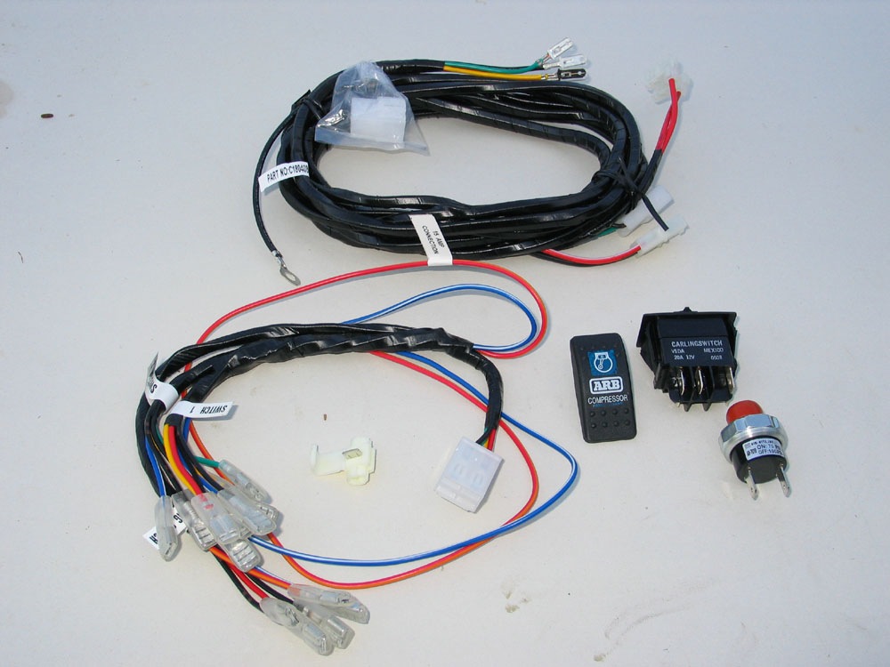 |
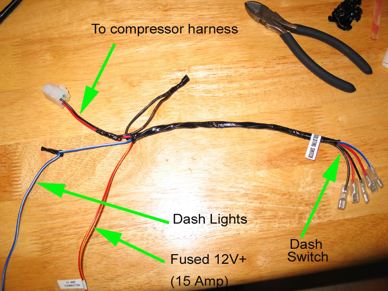
A close-up of the wiring harness and switches. For my installation I wanted to do a "full pneumatic" system - that is, a system where there are no solenoids used, everything downstream of the compressor is pneumatic only, and the only electrical part of the system is the power to run the compressor. More on this later - for now, the important thing to note is that the supplied wiring harness, as seen at left, comes in 2 parts and will have to be modified if not following the ARB electro-pneumatic route. To help keep things clear, I call the larger portion of the harness (at the top of this pic) the "compressor harness" and the smaller section the "switch harness" (where 'switch' refers to the compressor activation switch). |
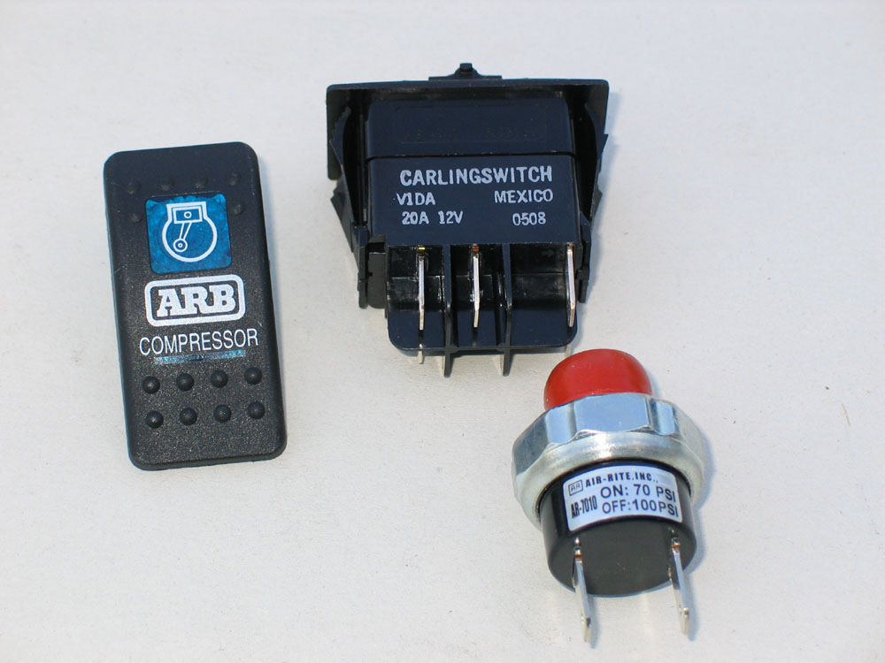 |
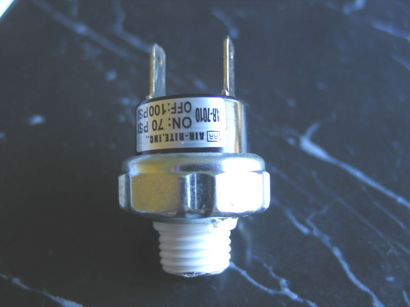
The dash-mounted, compressor activation switch (left) and the compressor's pressure switch. The compressor activation switch is used to turn the compressor on or off and is used in both electro-pneumatic installations as well as full pneumatic systems. The pressure switch installs in the compressor's small tank and, with the dash mount switch on, automatically switches the compressor on when the tank pressure falls below 70psi and switches it off when the pressure reaches 100psi. |
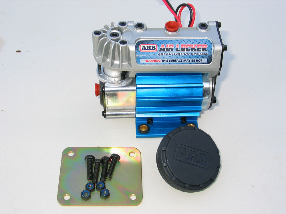 |
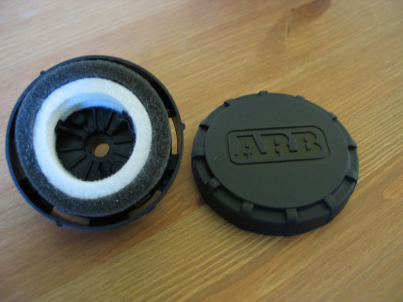
The compressor, mounting plate, and air filter. The air filter is used to filter the incoming air to the compressor. |
 |
End view of the compressor. Note the two red rubber plugs - one on top where the pressure switch screws in, and one on the end where the air filter screws in. |
 |
If we take the end cap off the unit we can see inside the small storage tank (left) and the electric motor. |
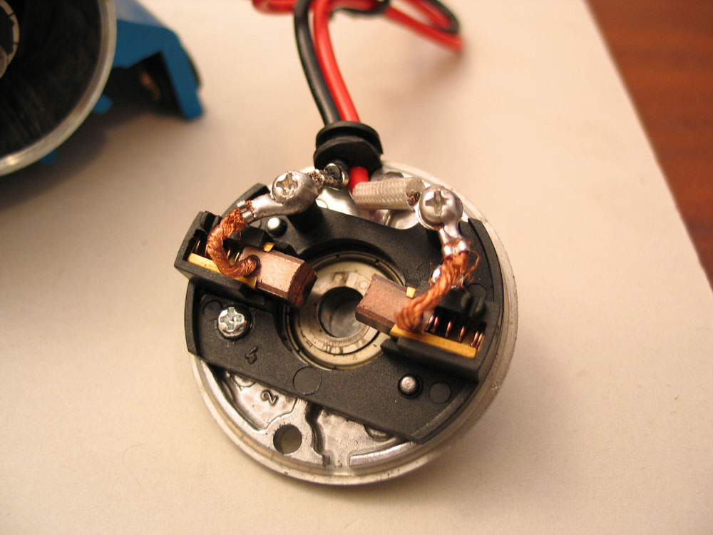 |
Close-up view of the motor's brushes - which are available separately and are user-serviceable That said - you need some skill and a big chunk of patience to finesse the brush cover back on - be warned!! |
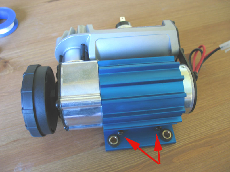 |
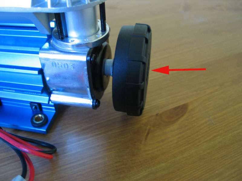
One of the coolest features of the compressor is the fact that you have 270° of freedom in choosing how to rotate the compressor in its mount. By loosening the two small hex-head motor mount screws (red arrows) you can loosen the mount and rotate the compressor in the mount anywhere from 90° to the left, through vertical, to 90° to the right. |
 |
Here the compressor is rotated about 45° to the right in its mount. |
Preparing the Compressor for Installation |
|
 |
Unpack the kit and lay it all out on a clean work surface. Remove the caps from the pressure switch and wrap the threads with Teflon tape. |
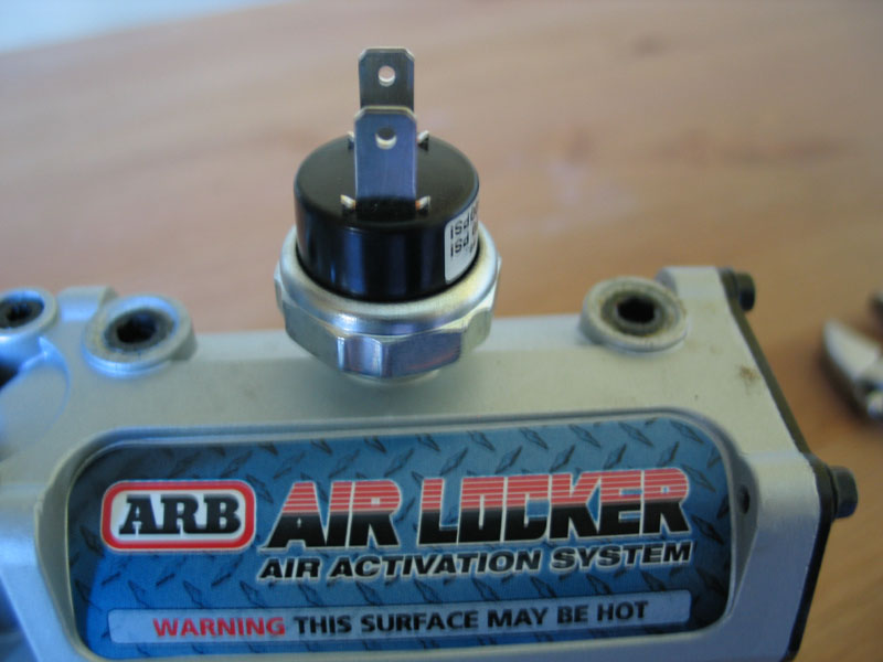 |
Remove the rubber plug from the port on the top of the tank and install the pressure switch. Snug it up but don't strip the threads! |
 |
Snap the two halves of the air filter together, being sure to line up the slots. |
 |
Apply Teflon tape to the threads of the air filter, remove the red rubber plug in the end of the compressor, and thread in the air filter. Note that you can also thread in a 1/4" NPT hose barb and use a length of tubing to relocate the air filter to a more suitable location. This can be useful should, for example, you choose to mount the compressor in a hot, dirty engine bay. The ARB manual contains details on max allowable lengths for different diameters of tube. |
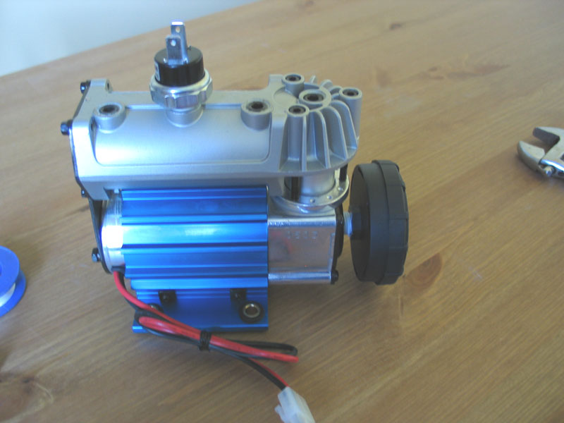 |
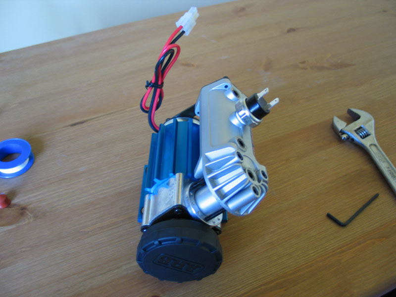
Ready to install, the compressor looks like this. |
Modifying the Harness for a Full Pneumatic Installation.If you are using ARB's locker activation switches and solenoids, you simply follow the supplied installation instructions which are complete and very good. Obviously no modifications are necessary. However, in a pneumatic installation, much of the supplied wiring harness is unnecessary. Essentially, all you need is the part that connects a fused 12V+ source to the compressor through the dash-mounted activation switch and pressure switch, along with ground connections and a dash-lighting 12V source to illuminate the switch. |
|
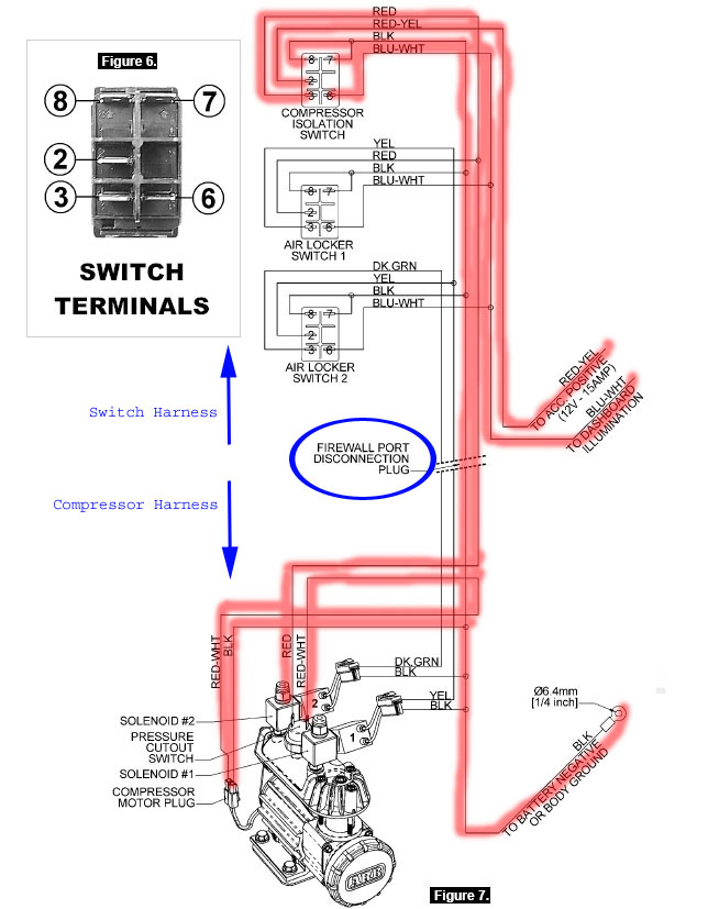 |
This diagram, from the ARB manual, illustrates the wiring for the compressor. The portions highlighted in red are those that you need to retain for a full pneumatic installation. Note that the "Firewall Port Disconnection Plug" is the place where the "switch harness" (upper part of the diagram) connects to the "compressor harness" (lower part of the diagram). To modify the harness as shown, you essentially just cut off the unneeded parts - those that connect to the solenoids and the ARB dash-mount locker-activation switches. |
 |
The modified switch harness looks like this. |
 |
To modify the compressor harness, cut off the 2 solenoid connectors (circled in red) as they will not be needed. |
Pneumatic ActivationSo why go to all the trouble of modifying parts and sourcing and plumbing special pneumatic switches? Simplicity and reliability are my answer. As I mentioned, the ARB electro-pneumatic activation system is very clean and professional looking and seems to have been designed with an eye to integrating cleanly and neatly into existing interiors. As you shall see, running full pneumatics from the compressor to the locker activation switches to the lockers is not nearly as neat and clean. However, the electro-pneumatic system does employ more parts, more wiring, and in particular solenoids that could represent a possible failure point. So, if you have a buggy you beat the daylights out of, one with no real clean dash to mess up with bulky pneumatic switches, a rig that could hardly be called "weather-proof" that you run hard in all kinds of brutal conditions - from smashing rocks to mud and deep water, you already know that eliminating any and all possible points of failure is a good thing. That's the case with my rig - so I decided on a full pneumatic system. What this means is that air is supplied by the compressor, and is controlled through a pneumatic switch (much like a small hydraulic valve) on the way to the locker. It's a purely "manual" system, with no additional electronics involved. The key to such a system is, of course, the pneumatic switch itself. There are many different kinds available on the market that are suitable - and they can be purchased everywhere from tractor-trailer suppliers to hydraulics/pneumatics shops to good on-line retailers such as McMaster-Carr. Of course, the first thing we need to do before ordering a suitable switch is to understand the terminology associated with pneumatics, the type of switch we need, and how to read a pneumatic switch diagram. Think of this as being similar to electronics - in that it would be hard to order an electrical switch or solenoid if we couldn't read or understand an electrical diagram. The proper name for a "pneumatic switch" is a "directional control valve" (I shall use the terms "switch" and "valve" interchangeably when discussing pneumatic control valves). A directional control valve has a valve body, internal passages, and a sliding spool. The sliding spool will connect and disconnect internal flow passages within the valve body resulting in the control of airflow direction. Note that it doesn't throttle or meter the airflow or regulate the pressure - it just changes the direction of the airflow. |
|
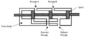 |
This diagram shows a typical directional control valve. Air pressure is supplied to the Pressure Passage. Depending on the position of the sliding spool this airflow is either connected to Passage A while Passage B is connected to the Exhaust Passage, or the airflow is connected to Passage B while Passage A is connected to exhaust. |
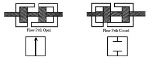 |
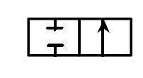
Directional control valve's are normally classified according to the number of possible flow paths or "ways" they have. The simplest example is a 2-way control valve. Obviously, this type of valve has only 2 possible paths - flow path open or flow path closed. In other words - "on" or "off". |
This diagram illustrates a 2-way valve and shows the ANSI symbols for each of the valve's positions. Often, in describing a directional control valve, we also include the number of positions the actuator has. This simple valve illustrated at left would be described as a "2-way, 2 position" valve. |
|
In order to actuate our ARB air lockers, we need a slightly more complicated switch. As we know from reading the ARB Install Part 1 - ARB 14-Bolt Air Locker Install article, in order to operate an ARB we supply it with air pressure to lock it, and exhaust this pressure so that it unlocks via the internal return springs. Knowing this, we can see why a 2-way switch won't work - because in either position there is no path for the air to exhaust, so, regardless of the switch position, the locker would remain pressurized and locked. |
|
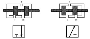 |
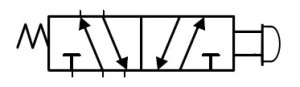
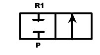
What we need is a 3-way, 2-position valve. A 3-way, 2-position valve will alternately pressurize or exhaust a single port. In the case of our ARB - when the actuator is in one position, pressure is supplied to the port and the locker locks and remains locked. When the actuator is moved to the other position, the air pressure supply is blocked, and the port is vented to exhaust, allowing the locker to unlock. |
The figure above illustrates a 3-way, 2-position valve, with the accompanying symbols. In our installation, the port labelled"P" would be where we connect the air supply line from the compressor/air source, the port "A" would be where we connect the air line running to the locker, and the port "Ex" would be the exhaust port. As for the symbols, note that a blocked port is represented by a "T" symbol, and that airflow between ports is represented by an arrow showing the direction of flow. Knowing this, we can see that the position on the left of this diagram would be "locker unlocked" (pressure port blocked, line from locker exhausted) and the position on the right would be "locked" (pressure supplied to the locker line and the exhaust port blocked). |
|
Reading the ANSI symbols. |
|
 |
When browsing a catalogue of pneumatic valves or switches we see that the type of switch is illustrated using the ANSI symbols we have seen. A typical switch may look something like this. |
PositionsThe number of positions the switch has is illustrated by the number of boxes drawn. Each box represents the flow path that is active when the switch is in that position. For example: |
|
 |
A 2-position switch would have 2 boxes. |
 |
A 3-position switch would have 3 boxes. |
Flow PathsEach box of the switch diagram will contain lines and symbols that depict the flow paths in the valve when the switch is in that position. |
|
|
Recall our original example of the simplest on/off valve. Its diagram would look like this. Note that in the diagram the ports may or may not be indicated by tick-marks outside the box and the ports may or may not be labelled or numbered. All three of these diagrams illustrate the same thing - a simple 2-way, 2-position switch. |
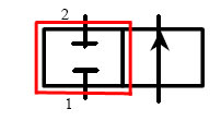 |
In this position, both ports are blocked, no air flows, and the switch is "Off". |
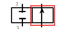 |
In this position, the two ports are connected, the air flows in the direction indicated - from port 1 to port 2 - and the switch is "On". |
ActuatorsThe symbols for the valve actuators are drawn on the end of the position boxes. They are drawn next to the box that illustrates the flow path that exists when that actuator has control. An example should clarify. |
|
|
In this example, the symbol on the far left represents a spring, and the symbol on the right represents a push button. It's a spring-loaded push-button switch. It has two boxes - so we know it's a 2-position switch. Obviously, in one position the button has control (when it has been pushed), and in the other position the spring would have control (when it's extended). |
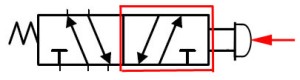 |
With the button pushed, the spring compresses, and the flow paths will be those illustrated in the box next to the button symbol. |
 |
With the button released, the spring extends, and the flow paths will be those illustrated in the box next to the spring symbol. |
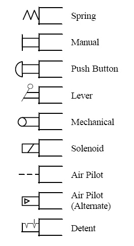 |
This chart shows common types of actuators you might see. |
|
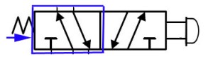
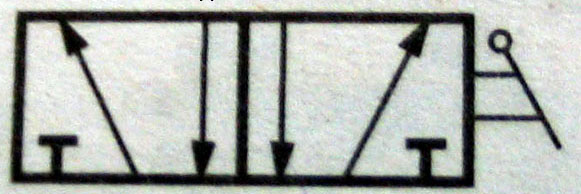
Note that, even for a multi-position switch there may be only one actuator drawn if that type of actuator is capable of controlling a number of different positions. The most common type of actuator of this sort would be the lever (or joystick) actuated valve - much like a multi-position hydraulic valve (as seen on tow trucks, etc.). In this case, only the single symbol for the lever is shown. At left are a picture of just such a valve and its ANSI diagram. Q: For bonus marks, what type of switch is this? You should be able to tell by now from reading the diagram. A: It's a 5-way, 2-position lever control valve! |
A Pneumatic Switch to Control an ARBSo, given all that we now know, what would the diagram for a switch that can control our ARB air locker look like? We should be able to draw it ourselves at this point. |
|
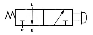 |
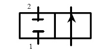
Here's the diagram for a spring-loaded, push-button, 3-way, 2-position directional control valve. Quiz: Assuming the ports are labelled P for air pressure supply, L for line to locker, and E for exhaust, would you push the button in to lock the locker or release it to lock the locker? Answer: Push it in. Because to lock, we want to connect P to L and block E. We can see this is the case in the box next to the button - therefore we push the button to lock. |
Note: Many small pneumatic switches may not have an obvious exhaust port. Instead they vent through the body of the switch. Regardless, the ANSI diagram should still show it as a 3-way, 2-position switch. Another advantage to using a pneumatic switch to control your air locker is that they are available with a seemingly endless number of different methods of activation - you aren't limited to a dash-mount switch - there are levers, push-buttons, twist-knobs, cable-pull, and even pedal-actuated models available. Putting it all Together - the CKSA12 Compressor and Pneumatic Switches to Control an ARB. |
|
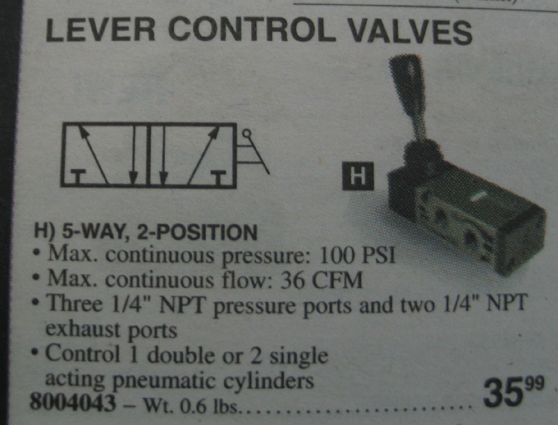 |
This is the page from the catalogue of my local supplier (Princess Auto) illustrating the valve I chose to control my rear ARB. The reason it is a 5-way is because I have a different brand of air locker in my front axle (that requires a 5-way switch due to different operation) and I wanted the two switches to match. It's not a problem as I can simply block the unneeded ports in the switch that controls the ARB. |
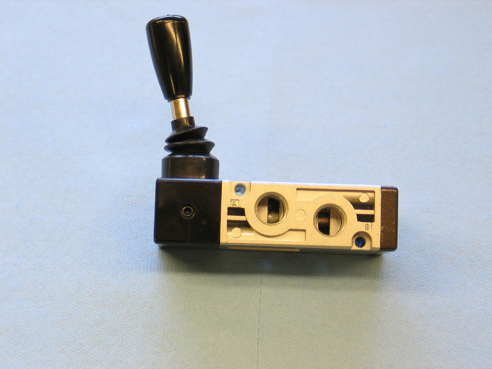 |
This side of the valve has the two ports illustrated on the top of the ANSI box diagrams. They are labelled A and B. If you look carefully you can see the sliding spool through the ports. |
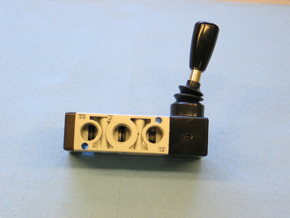 |
This side has the three ports illustrated on the bottom of the box diagrams. They are labelled R1, P, and R2. |
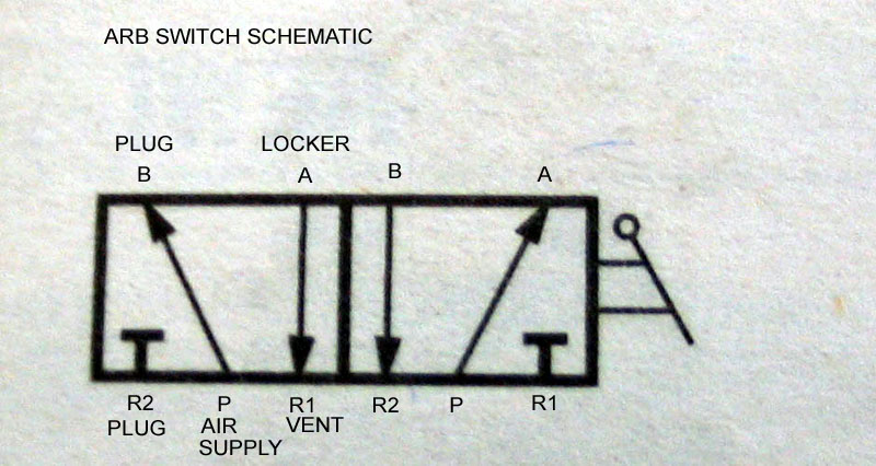 |
Here's the switch diagram labelled for ARB control. |
 |
Here's how the ports are configured / plumbed to control the ARB. |
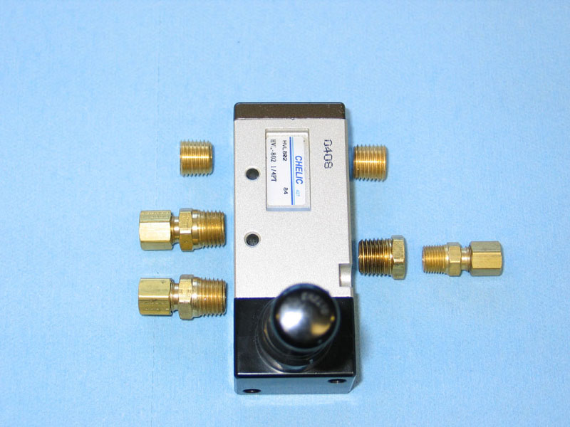 |
Showing the fittings used. Top two are simply brass 1/4" NPT plugs to block off unneeded ports. Two on left are 1/4" NPT to 1/4" compression fitting. 1/4" compression fittings connect to 1/4" SAE air-brake plastic hose that connects to the compressor (middle fitting) and runs to an exhaust (bottom fitting). You want to run an exhaust line because just leaving the port open would allow dirt into the valve which would damage the sliding spool and internal seal surfaces. Right middle fitting is a 1/4" NPT to 3/16" compression for connecting to the rear ARB locker. With a bit of effort you can get a 3/16" compression fitting over the 5mm ARB supplied blue air line. |
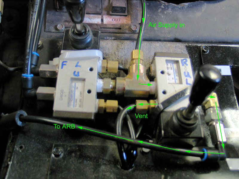 |
As I mentioned, I wanted 2 matching pneumatic switches to control two different air lockers. Here they are laid out on the "centre console" (such as it is) of the buggy. The one on the left, with the stick to the front, controls the front (non-ARB) air locker. The one on the right controls the rear ARB. The air flow through the ARB switch is indicated in the picture. Note that the 2 switches share the incoming air supply from the CKSA12 via a T fitting. There's a reason for this...see below. |
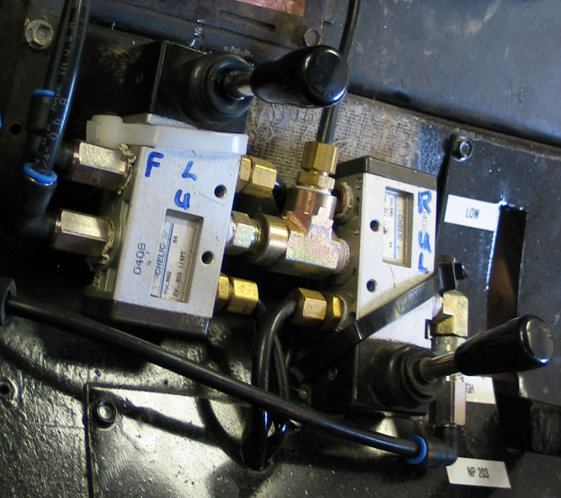 |
Another view of the valves. Notice that they are bulky and with all the air line connections not a very tidy install (well, that and because of my chronic lack of time/patience/skill and total apathy towards how the rig looks!) You can get much more compact 3-way pneumatic switches, but I do really like the little joysticks - super easy to reach and use - even without looking. |
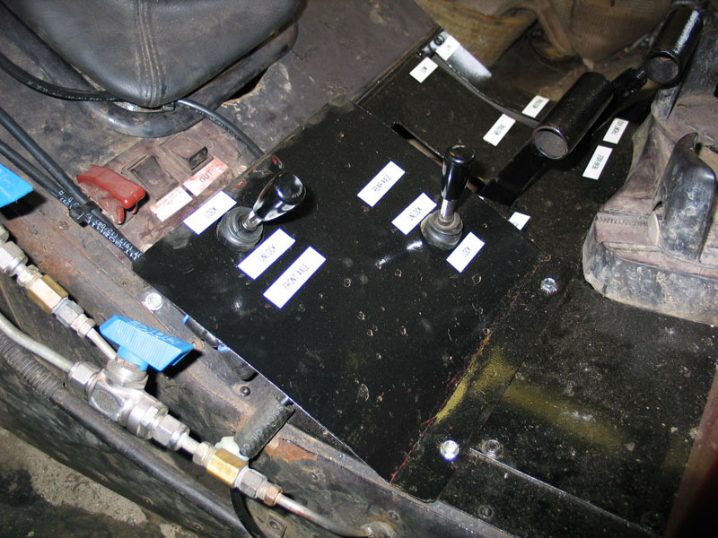 |
OK, maybe I'm not TOTALLY apathetic about how booty-fab my rig looks - I made this rudimentary cover to cover the valves and just let the joysticks protrude. If you had any amount of skill you could probably make a tidy little installation of these valves! |
 |
I mounted my new CKSA12 compressor inside the rig, up beside the "dash". This way it's kept reasonably clean and dry and has decent, clean air supply. It isn't exactly "whisper quiet" but if you have no leaks its cycle time is infrequent and it only runs very briefly to charge the small tank. In fact, with the sound of a V8 in an open buggy as well as my daughter's constant cries of "Faster, Daddy, faster!" and my son yelling "Use the Cherry Bombs Dad - use the Cherry Bombs!" (I think he thinks they're some kind of "switched" thing like Nitrous instead of me just planting my foot on the idiot pedal) - I hardly hear it at all! Of course, if you have such extravagant luxuries as, oh say, doors and a roof and a hood, you could easily tuck it away in the engine bay and never hear it at all. I particularly like that it's well protected where it is. And this is the great thing about the CKSA12 - it's so small you can mount it anywhere and be worry free because you have a completely independent system to run your lockers. Nothing's worse than having lockers that don't work - and now I don't have to worry about broken fan belts on an OBA compressor or running out of CO2 in a tank. |
 |
Note that I made good use of the rotating mount capability so that the air supply line would lay as flat as possible. |
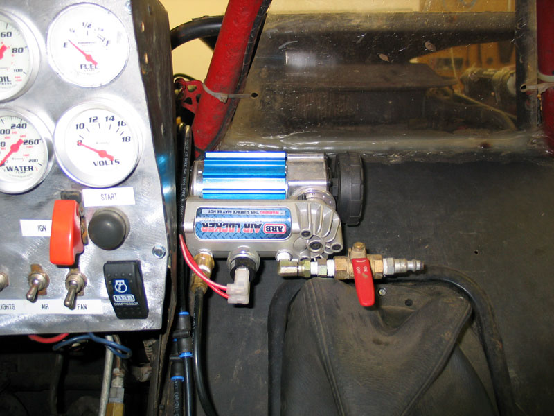 |
The CKSA12 has 2 supply ports - one is used for each solenoid in a "normal" installation. I supplied both my pneumatic switches from a single port (on the left in this pic) using a T-fitting at the switches so that I had the other port free. As you can see, to this free port I added a manual valve and quick-connect fitting. This way, if I ever do have a problem with the compressor, I can hook up virtually any other source of air to charge the small tank and retain full locker capability without having to mess around with the air lines. |
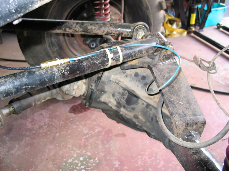 |
Speaking of air lines - you may have noticed that in an earlier picture I talked about connecting the 5mm ARB blue air line to my pneumatic switch using a 3/16" compression fitting - but in these more recent pics I'm running 1/4" SAE air brake hose from the switch. Since here in Canada the ARB line is harder to come by than 1/4" air brake hose (which can be bought almost anywhere for pennies a foot) I decided to minimize the use of the 5mm line. That way I have a coil of the 5mm line (that came with my ARB locker) for spare/repairs that, because I use only a small length, will last a very long time. Everywhere else I use the cheap, readily available 1/4" line. The only place I use the 5mm is to connect to the axle housing bulkhead fitting, as shown in this pic. |
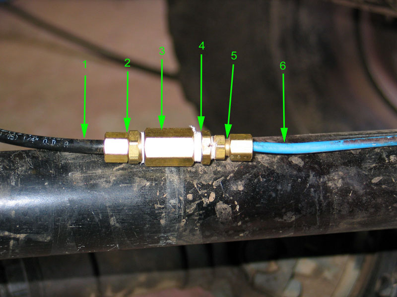 |
To join the 1/4" air brake hose to the 5mm blue line I used: 1) 1/4" SAE air brake
hose |
SERIOUSLY abusive testingThe following series of pictures and video were recently sent to me by ARB's Engineering Supervisor in Melbourne, Australia. They demonstrate clearly just how seriously ARB take their products and their durability. Subjecting a product like this to this kind of abuse shows the confidence they have in it - and the impressive results should fill you with confidence too. |
|
|
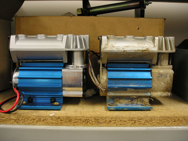
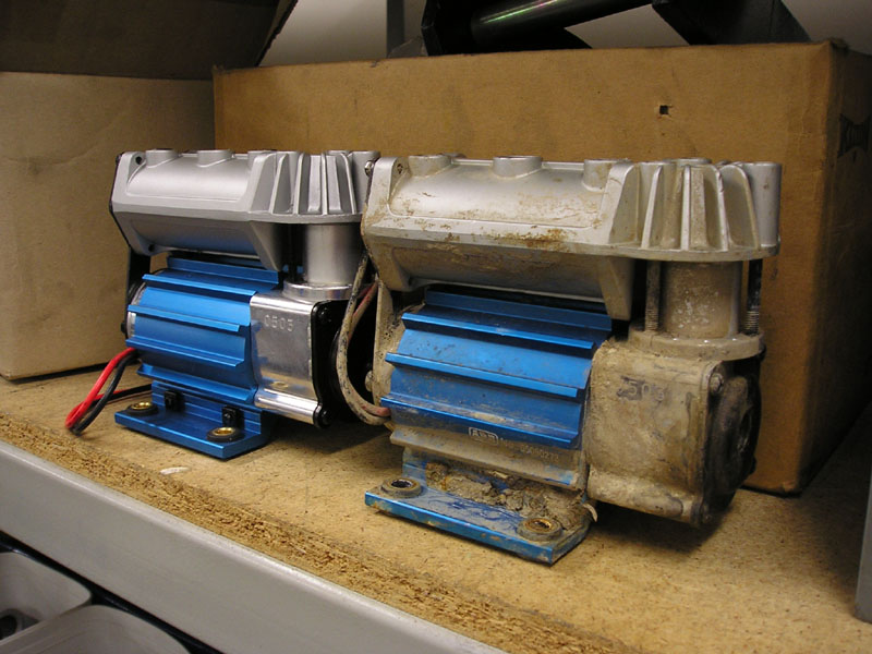
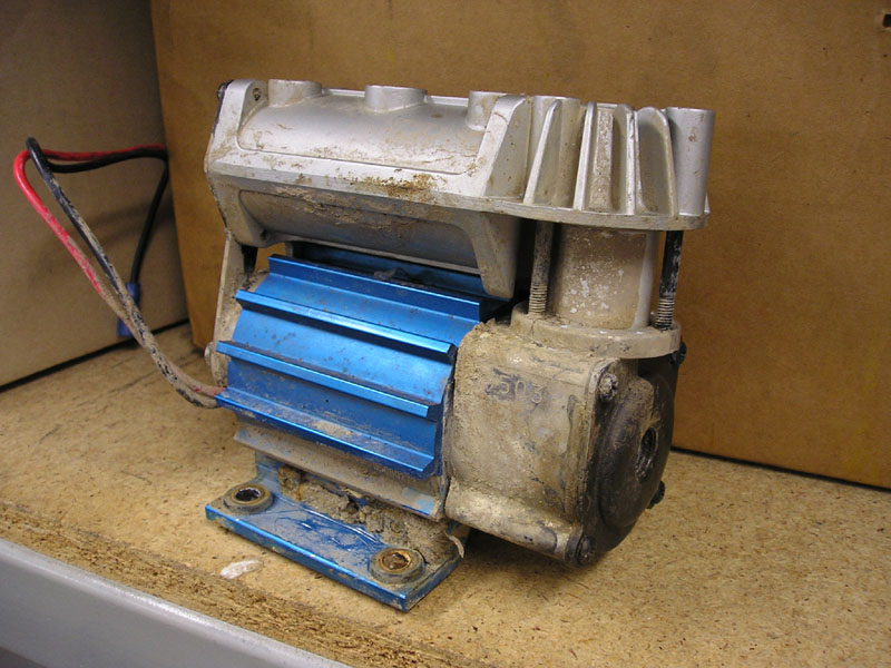
This series shows a brand new CKS compressor next to one that was installed in the rear wheel-well of a Land Rover 110 that then spent two solid weeks off road on the beaches of South Australia. The unit was mounted in the gravel blast-zone directly behind the tire - possibly the worst possible location to mount one. After this abuse the unit still runs 100% and dyno'd up to full performance. |
 |
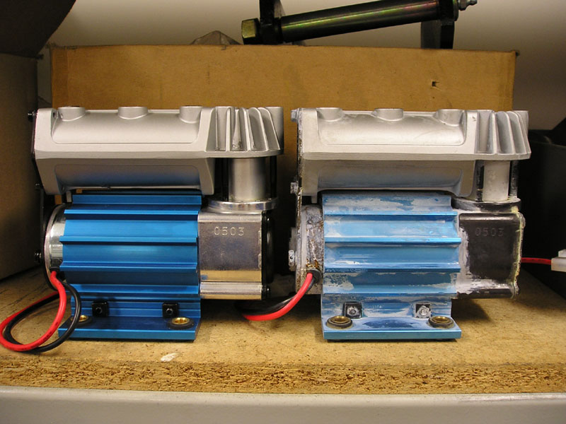
This is a pic of
a unit that ARB high-temperature tested shown beside a new unit (left) for
contrast. First It was baked it for a couple of days at 120°C after
which there was no identifiable damage of any kind. Next they stepped the
temperature up to 150°C. Finally they stepped the temperature up to
180°C for a whole day which is the point at which the wiring insulation
actually baked itself brittle, the plug changed to that brown colour, and
the sticker shrivelled up. Also notice that they actually cooked it so much
that the blue anodizing of the motor mount became discoloured. This unit still runs to this day, and has suffered only minor performance degradation which ARB were able to detect on their computerized flow dyno. |
|
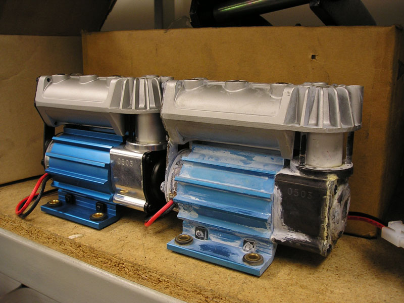
These pics are of
a unit that spent over a full month completely submerged in a super-saturated
solution of sea salt and water. Notice that the corrosive solution did get
through the zinc plating in a few spots on the motor tube, turned the aluminium
crank-case die-casting a very strange black colour, and left a hard-nasty
salt build-up on the rest of the whole unit. This unit is kept at ARB's head office in Melbourne, Australia in case anybody would like to stop by and see it fired up and dyno'd at full performance levels. |
| ARB CKS Compressor - Runs completely submerged !!! | Finally - click the title to the left to see a 2MB .avi video clip of the CKS compressor running completely submerged!! |
It's a rare thing that a company spends such time and effort abusively testing their products, and rarer still that they release the results to the public. My thanks to ARB for the pictures and video and congratulations to them for building such a seriously tough little unit! ConclusionThe new CKSA12 compact on-board air kit is a dandy little product. You won't be filling any tires with it or powering air tools - but at the job it is designed for - running air lockers - it is excellent. It's compact, easy to mount, reasonably quiet, simple to hookup and best of all - rugged, independent and reliable. I've been running mine for many months now and it easily and reliably runs both my air lockers. It occurs to me that it would also be an excellent choice for anyone with limited space or particularly for competitors looking to save weight anywhere they can. The only thing I could suggest for improvement would be if ARB themselves could design and produce a "full pneumatic" kit. With their usual attention to detail and if it were anything like their normal kit in terms of fit and finish, heck even I could end up with a clean, show-quality install. So how about it ARB? This little compressor works great, is amazingly rugged, and would be an excellent choice for anyone - whether running "full pneumatic" or the conventional electro-pneumatic. References:
Go to >>> ARB Install Part 1 - ARB 14-Bolt Air Locker Install |
|


 |
Sources: ARB USA 720 SW 34th St. |
|