 |
GM 10.5" 14-Bolt Gear Install and Setup By Bill "BillaVista" Ansell |
IntroductionThis article details a complete carrier change plus installation and setup of the ring and pinion gears in the GM 10.5" ring-gear 14-Bolt full-float rear axle. It assumes you are familiar with basic axle and differential terminology - i.e. that you can tell the difference between the carrier and the pinion nine times out of ten! |
 |
||||||||||||||||||||||||||||||||||||||||||||||
For more information on the 14-Bolt, be sure to check out the following articles:
Quick Ref. - Gear Setup Specs:
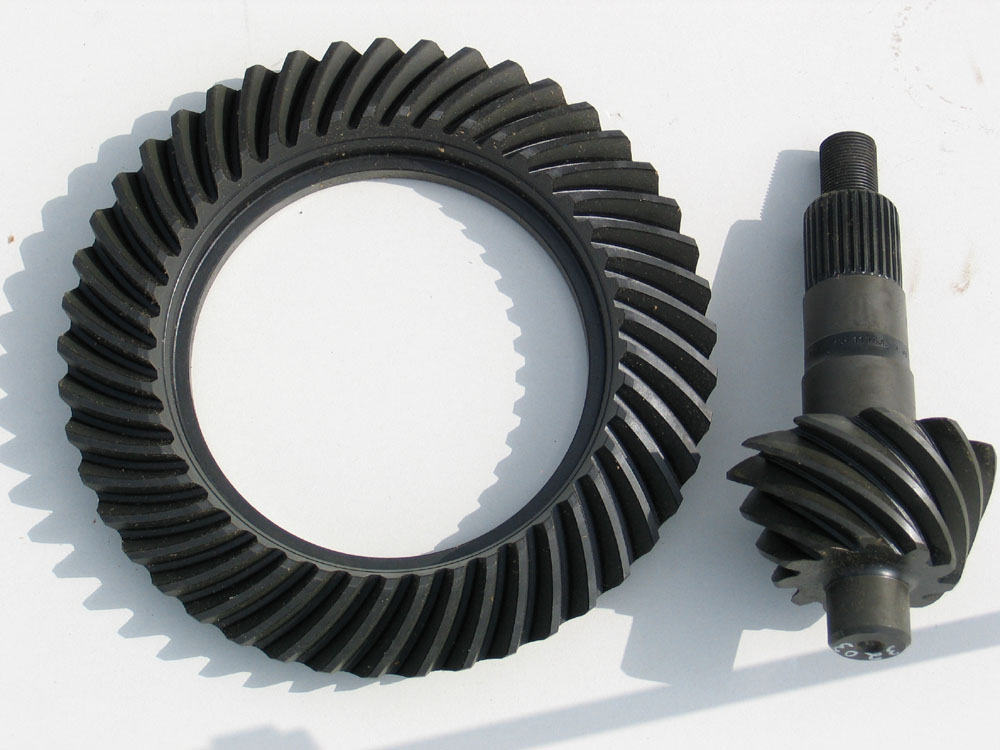
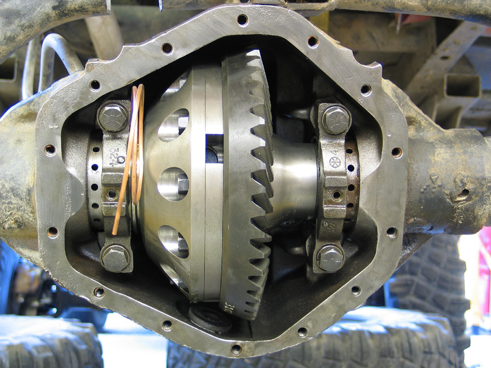
14-Bolt NomenclatureThere are a few unique characteristics/parts to the 14-Bolt. The following pictures illustrate the terms I'm going to use in the rest of the article.
|
|||||||||||||||||||||||||||||||||||||||||||||||
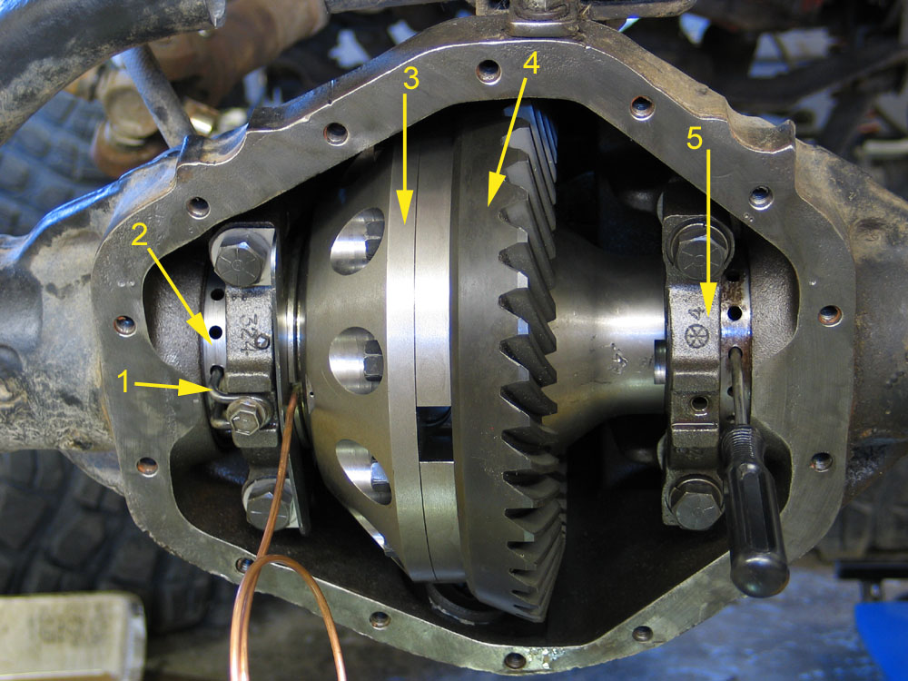 |
14-Bolt Differential 1. Adjusting Nut Lock (aka Adjusting Nut Retainer) |
|||||||||||||||||||||||||||||||||||||||||||
 |
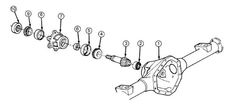
14-Bolt Pinion Assembly 1. Straddle Bearing Journal |
|||||||||||||||||||||||||||||||||||||||||||
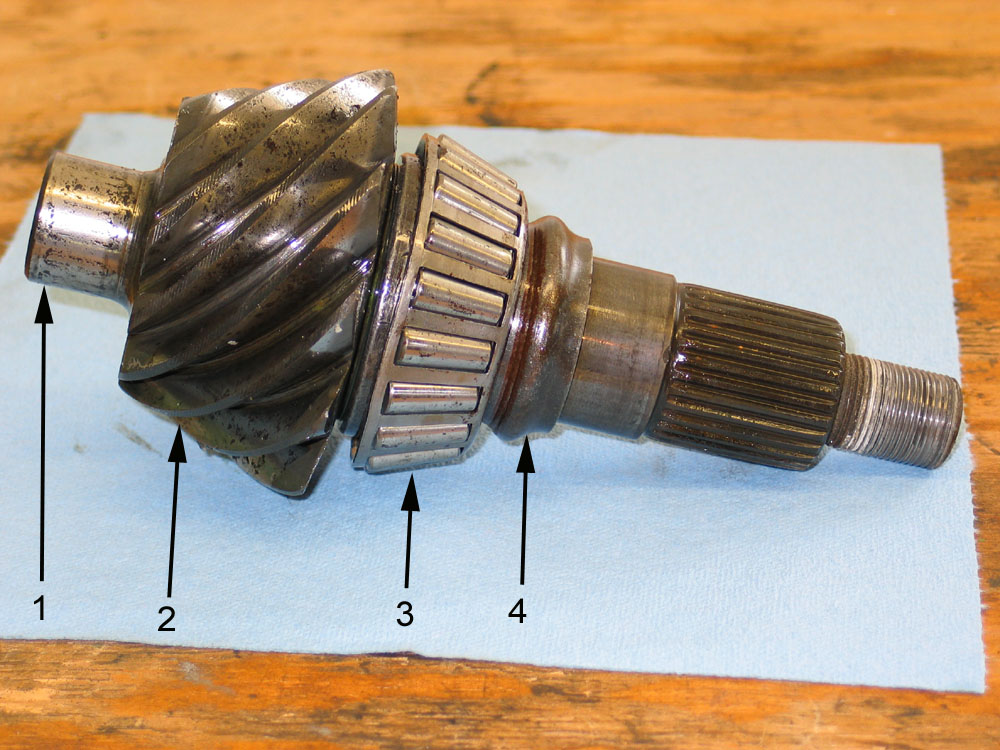 |
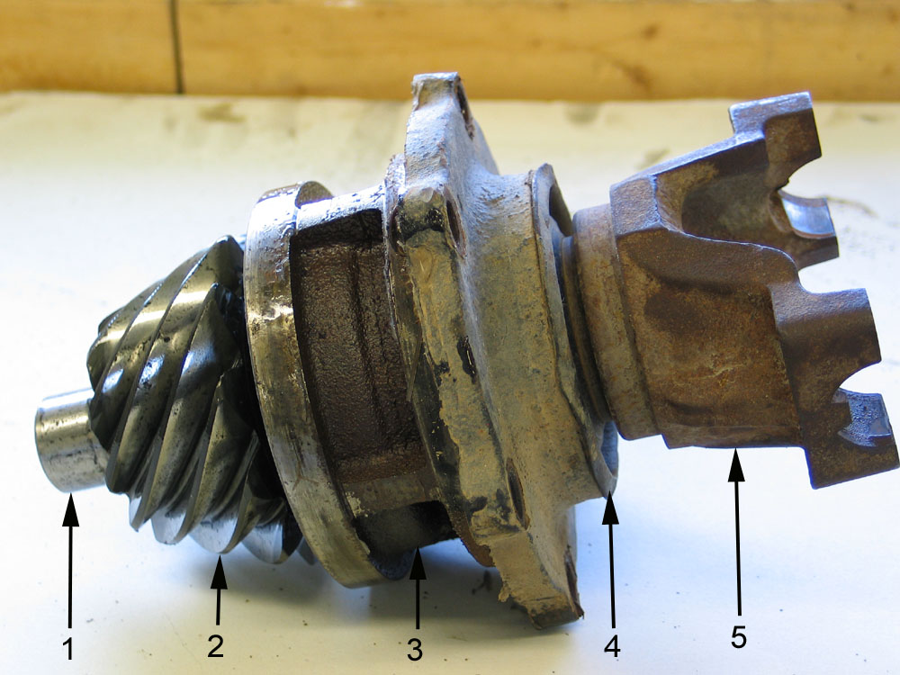
14-Bolt Pinion 1. Straddle Bearing Journal |
|||||||||||||||||||||||||||||||||||||||||||
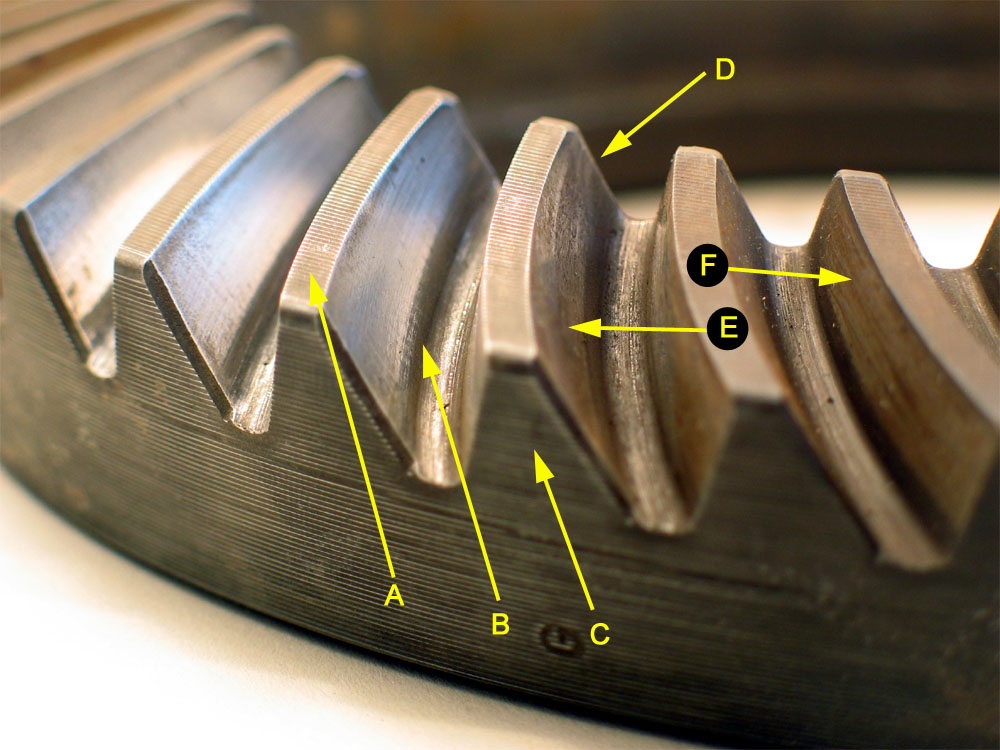 |
Ring Gear Tooth Nomenclature
* Don’t be mislead by the terms “coast” and “drive”, as the ring-gear can be driven by the pinion on either side of the teeth. Which side of the teeth will depend on if the gear-set is standard or reverse spiral and whether the vehicle is going forward or in reverse. |
|||||||||||||||||||||||||||||||||||||||||||
IntroductionSetting up ring and pinion gears may seem an intimidating job, but the entire process is really just a matter of adjusting four separate but inter-related settings until they all fall within specification. The four settings are: Backlash |
||||||||||||||||||||||||||||||||||||||||||||
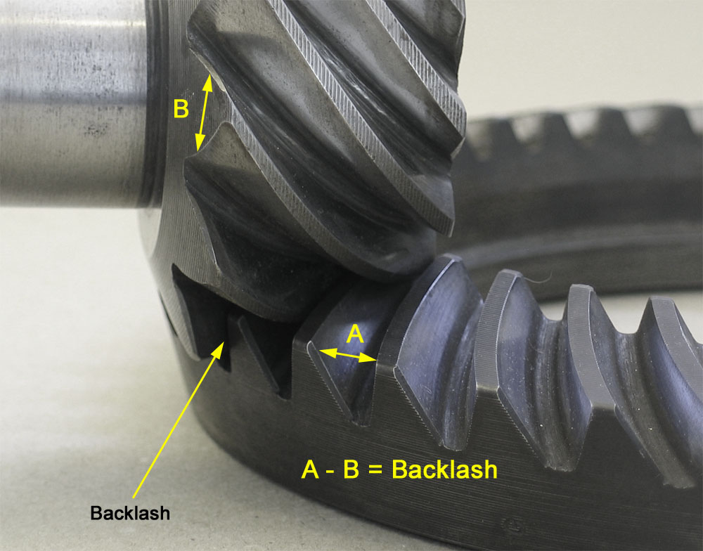 |
Backlash - the amount by which a tooth space exceeds the thickness of an engaging tooth. | |||||||||||||||||||||||||||||||||||||||||||
Pinion Depth Pinion-bearing Preload Carrier-bearing Preload Tear Down |
||||||||||||||||||||||||||||||||||||||||||||
 |
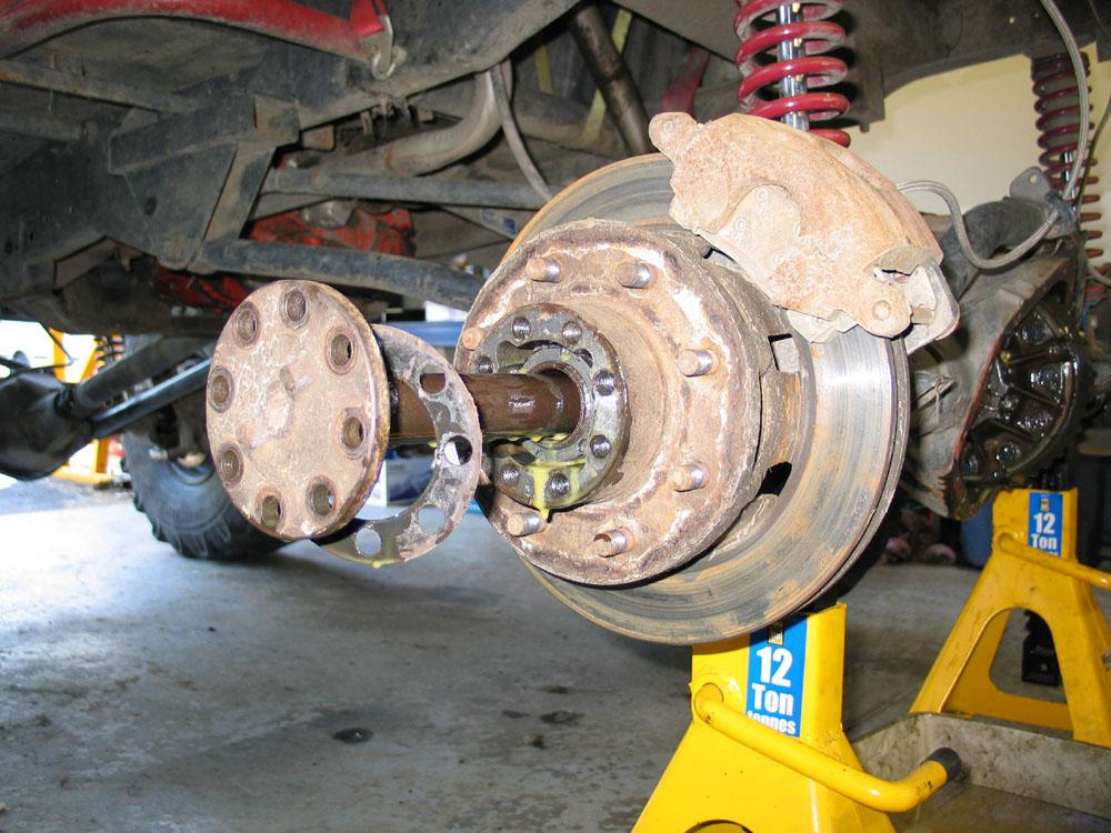
Loosen lug-nuts and remove the axle-flange to hub bolts. | |||||||||||||||||||||||||||||||||||||||||||
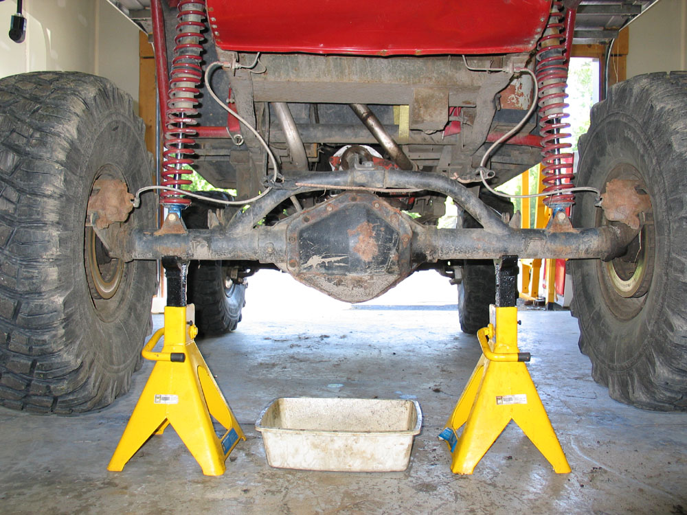 |
Jack up axle, and secure safely on jack stands. The job can be done with the axle in or out of the vehicle. I found it actually easier to do it with the axle still in the vehicle as I could then use the brakes to apply load to the gears when checking the pattern - more on that later. |
|||||||||||||||||||||||||||||||||||||||||||
 |
Tap the axle shafts out of the axle with a brass drift. Remove the axles and put them aside Do not leave them, covered in sticky gear oil, precariously leaning up against the wall in the corner where you do all your cutting and grinding so that they can fall over in the chips, slivers, and grinding dust...it doesn't aid the installation later! ...Don't ask! |
|||||||||||||||||||||||||||||||||||||||||||
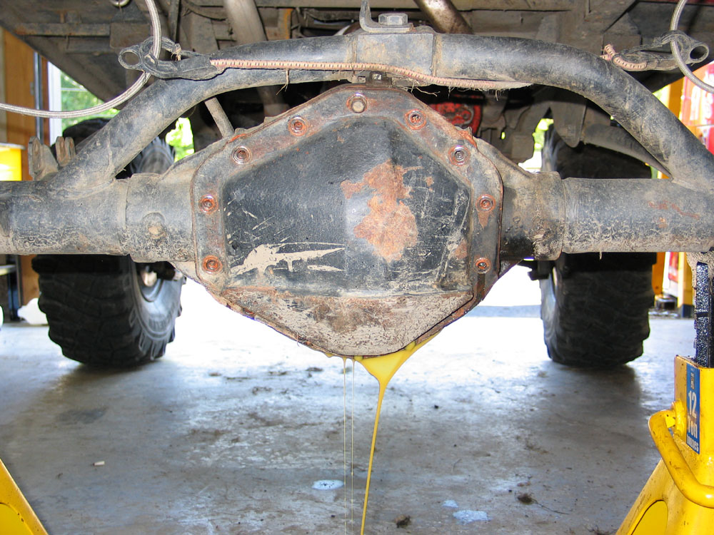 |
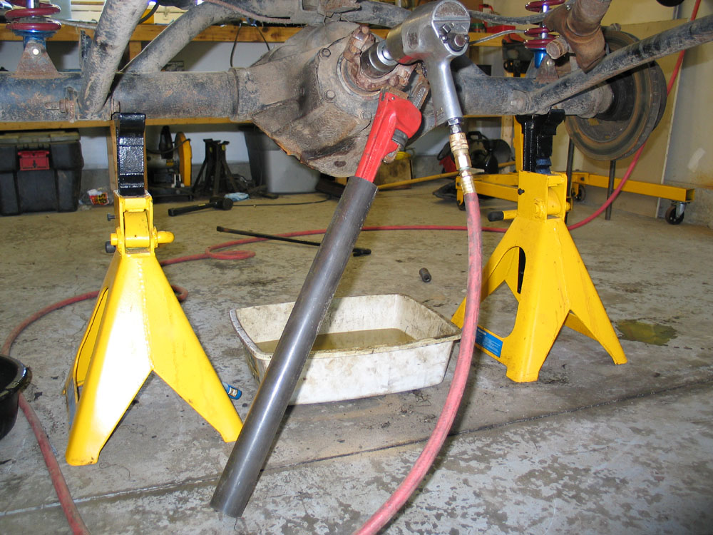
Remove the diff cover bolts except for the top-most one. Pry / knock the cover loose (be careful not to damage the sealing surface of the cover or axle housing) and drain the gear oil. Make sure you have a large enough pan - capacity is about 5.4 pints. When the oil has drained, remove the last bolt and the diff cover. Thoroughly clean the cover ready for installation. |
|||||||||||||||||||||||||||||||||||||||||||
 |
Remove the driveshaft U-bolts or straps and disconnect the driveshaft from the pinion yoke. | |||||||||||||||||||||||||||||||||||||||||||
 |
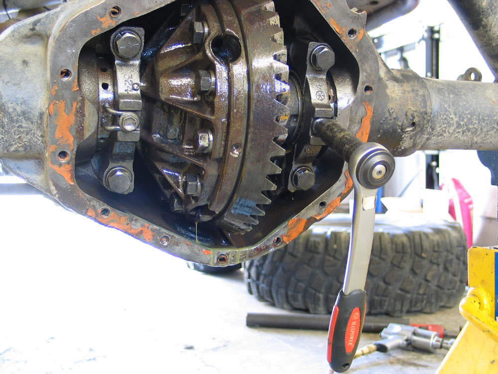
Before tearing down the diff, check the existing backlash with a dial-indicator. Strictly speaking, this step is only necessary if you will be re-using the gears. The reason you want to check it now, is so that you can re-install the same gears with the original backlash (assuming it was within spec) to avoid changing the gear tooth contact pattern since the gears have broken in together at this lash. In many axles this wouldn't even be an option, but because the 14-Bolt has such a wide range of acceptable backlash (0.003" - 0.012") it can be worth checking if you're going to be re-installing the same gears. I used new gears, but checked anyway, just for interest's sake. Backlash was 0.030"...pretty loose by anyone's standard! |
|||||||||||||||||||||||||||||||||||||||||||
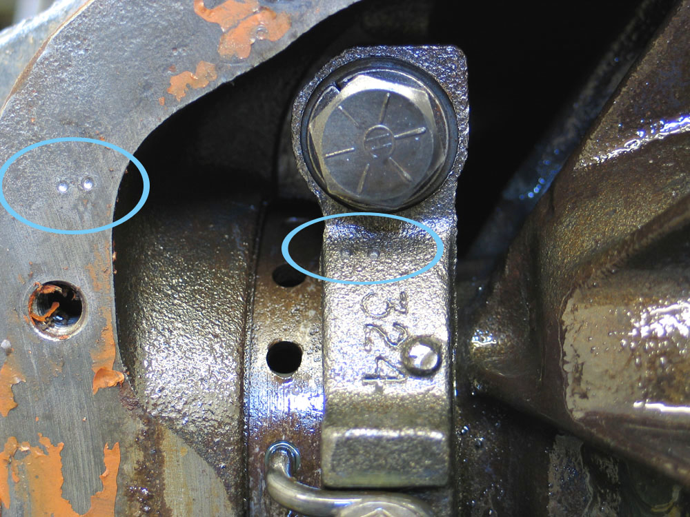 |
Before removing the carrier, be sure to mark the carrier bearing caps so that they can be re-installed in exactly the same orientation. I usually stamp two horizontal dots on the top of the left bearing cap and on the adjacent housing; and a single dot on the right. | |||||||||||||||||||||||||||||||||||||||||||
 |
Remove the bolts securing the adjusting-nut locks. Remove the adjusting-nut locks. Keep these small parts in a safe place during the project. ...Don't ask! |
|||||||||||||||||||||||||||||||||||||||||||
 |
Remove the carrier bearing bolts and caps. | |||||||||||||||||||||||||||||||||||||||||||
 |
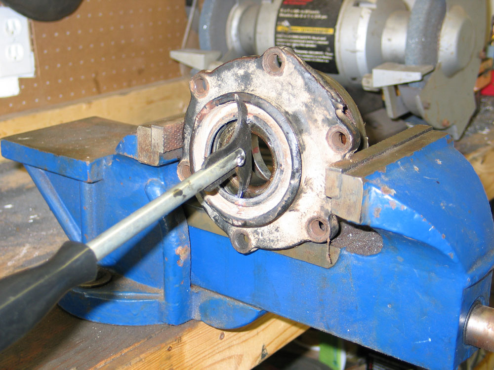
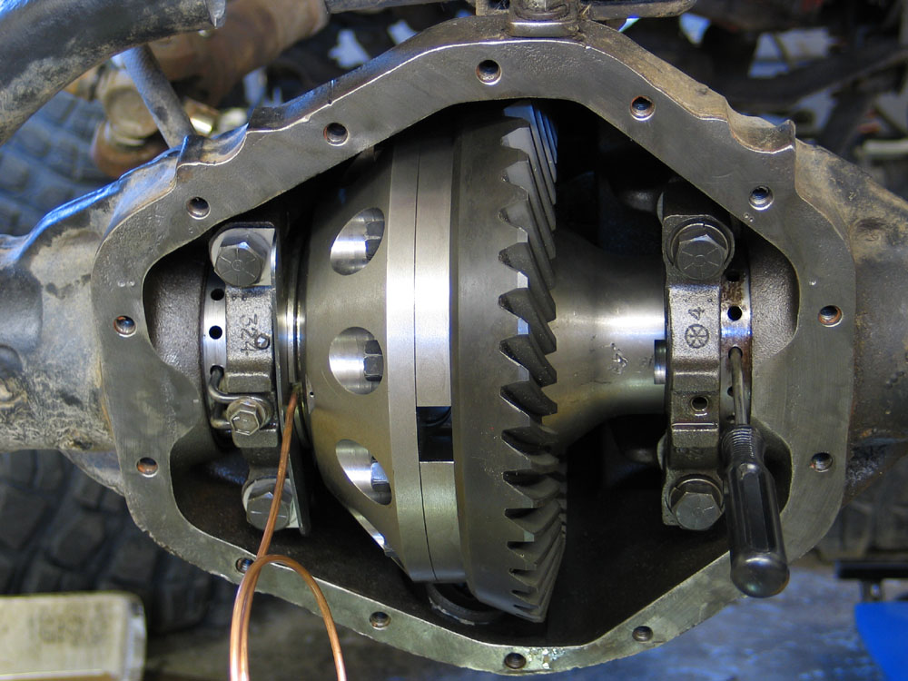
Loosen the adjusting nuts so that the carrier can be removed, and carefully remove the carrier. Be careful - it's quite heavy. It's best to use the proper spanner tool, but a #2 Phillips screwdriver will do. The right adjusting nut is loosened by moving the screwdriver handle DOWN. The left adjusting nut is loosened by moving the screwdriver handle UP. In other words, the adjusting nuts are both right-hand thread and screw into the housing. |
|||||||||||||||||||||||||||||||||||||||||||
 |
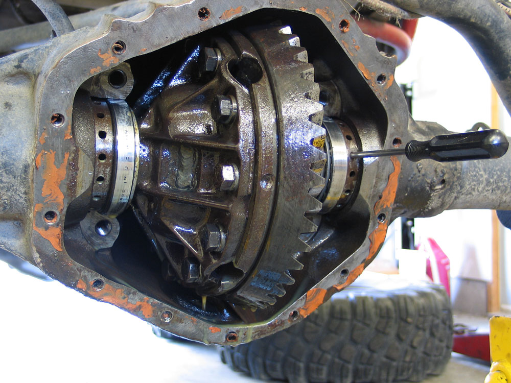
If you plan on re-using them, tag and keep the carrier bearing cups separate so that they can be re-installed on their original sides. Remove the carrier bearings from the carrier. Here I am using a clamshell-style carrier bearing puller. In the past I have used cheap 2-jaw pullers (that had to have the legs ground to fit in the carrier reliefs below the carrier bearings), hammer and chisel, heel-style pry-bars, and who knows what to remove carrier bearings. |
|||||||||||||||||||||||||||||||||||||||||||
 |
None of these methods works very well, all seem to damage the bearing during removal, and frankly I was tired of them. On top of that, the design of the stock 14-Bolt carrier leaves virtually no room to get a leg-style puller or a bearing separator in behind the carrier bearings. For more details check out my review of the Yukon Clamshell Bearing Puller from Randy's Ring & Pinion. |
|||||||||||||||||||||||||||||||||||||||||||
 |
If you're re-using the carrier, scribe an alignment mark on both halves so that it may be reassembled in the original orientation. If you're re-using both the carrier and the ring gear (i.e. if you're just performing maintenance on the differential inside the carrier), make the scribe line on the ring gear as well so everything can be re-assembled in the original position. Use a clamp or similar device to keep pressure on the two halves of the carrier as you remove the ring gear bolts because spring pressure from the differential will try and force the two halves apart. Remove and DISCARD the old ring gear bolts and lock washers. |
|||||||||||||||||||||||||||||||||||||||||||
 |
Hey - I'm just holding that screwdriver for illustrative purposes...I would, of course, never use the wrong tool for the job....oh no...simply unheard of! |
|||||||||||||||||||||||||||||||||||||||||||
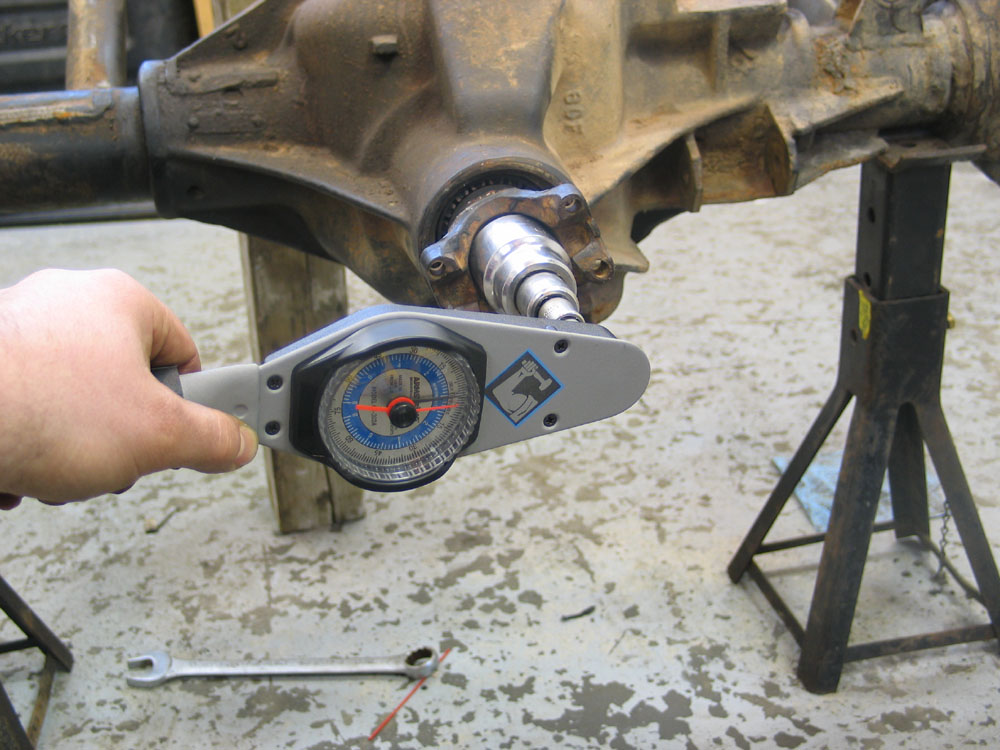 |
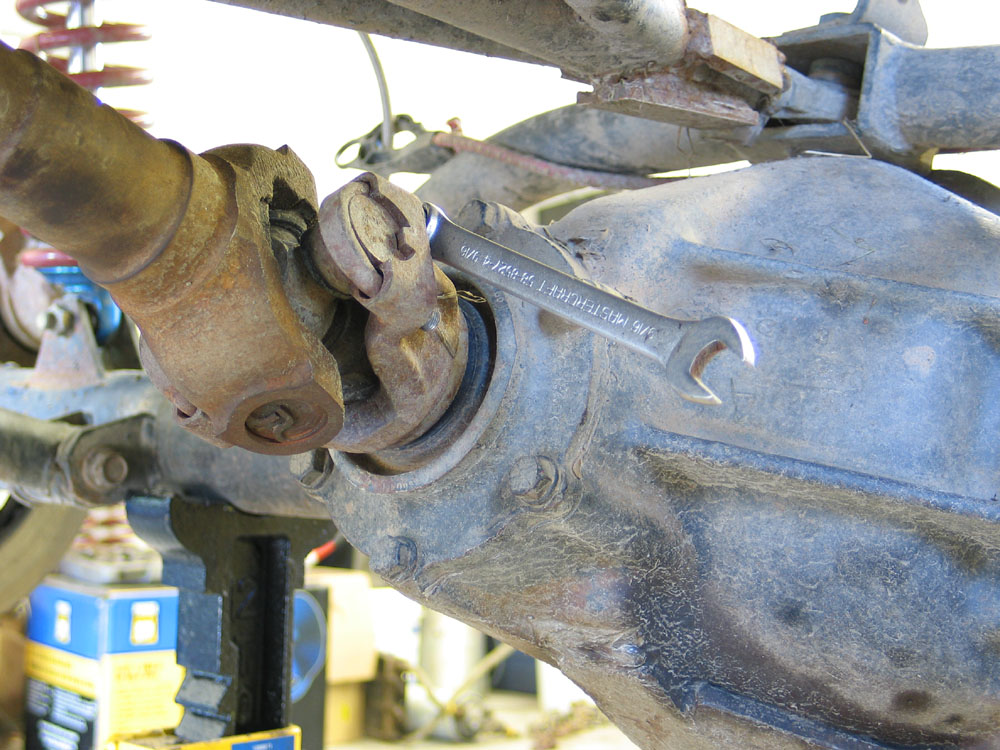
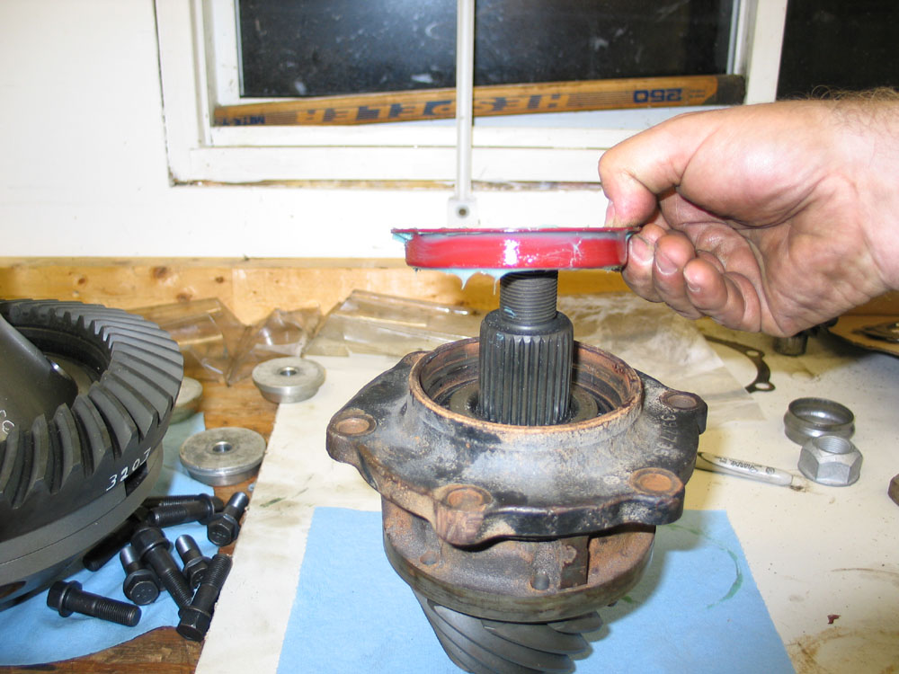
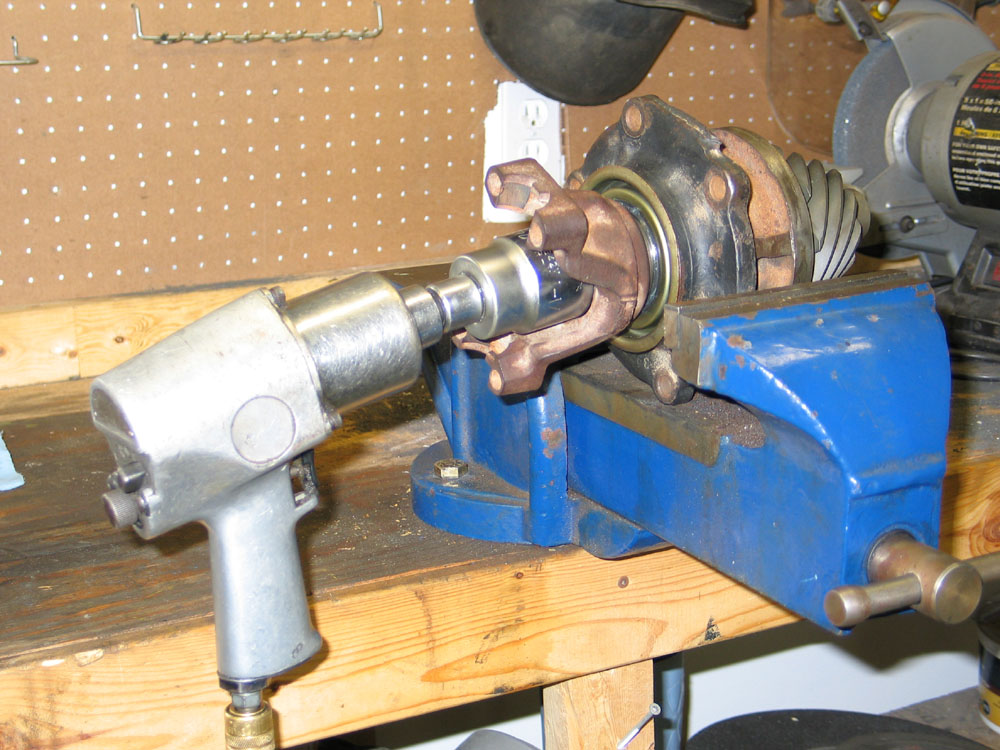
Before removing the pinion nut, and with the carrier removed, it can be beneficial to check the pinion bearing preload. This will give you some indication as to the health (or in my case - lack thereof) of your pinion bearings. To measure pinion bearing preload - use a beam- or dial-type inch-pound torque wrench on the pinion nut and measure the torque required to rotate the pinion. Do not read the initial torque it takes to start the pinion turning, but rather the steady torque it takes to keep the pinion rotating. Mine was only 2 in/lbs where the spec is 5-15 in/lbs for used bearings! Note: Yes, the eagle-eyed readers amongst you will notice that this is not a 14-Bolt in the picture. In fact, it looks suspiciously like a D60 front axle. Hey - sometimes a picture doesn't turn out and you have to use what you have available. |
|||||||||||||||||||||||||||||||||||||||||||
 |
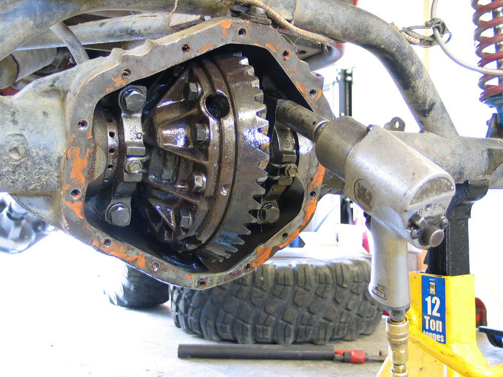
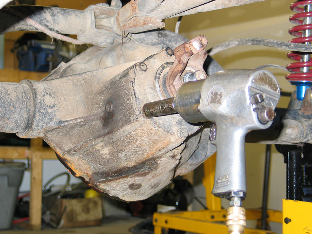
Remove the pinion nut. You will need a 1.5" socket to do so. Here, I am using an impact wrench on the pinion nut and, to prevent the yoke turning, a pipe wrench with a large extension on the handle so that it contacts the floor. | |||||||||||||||||||||||||||||||||||||||||||
 |
Next, remove the 6 bolts and lock washers that secure the pinion bearing retainer to the axle housing. To remove the pinion bearing retainer, you will probably have to use a brass drift to rap on the straddle bearing journal from the other side of the housing. Be careful not to drive the retainer out of the housing forcefully so that it flies out of the housing, bounces of the driveshaft, and skids across the floor... ...don't ask! Carefully remove the original pinion shims from the housing or the back of the bearing retainer. Measure the thickness of each shim with a 0-1" micrometer, total the numbers, and record this value as "original shim stack" for use later when setting up the gears. |
|||||||||||||||||||||||||||||||||||||||||||
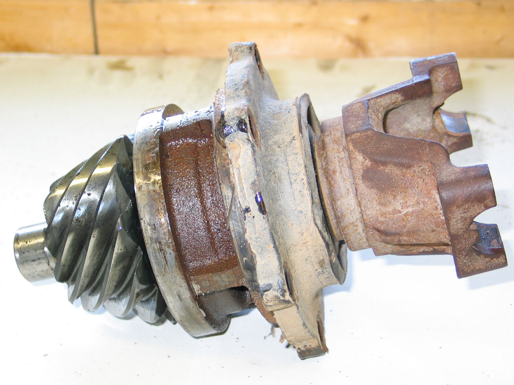 |
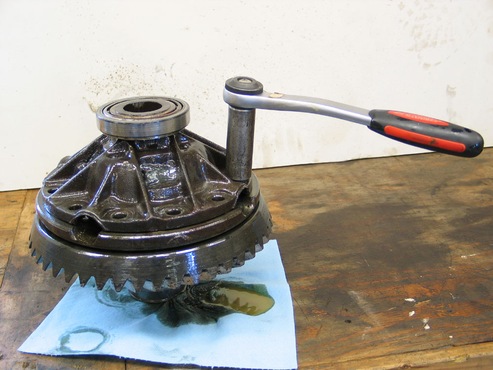
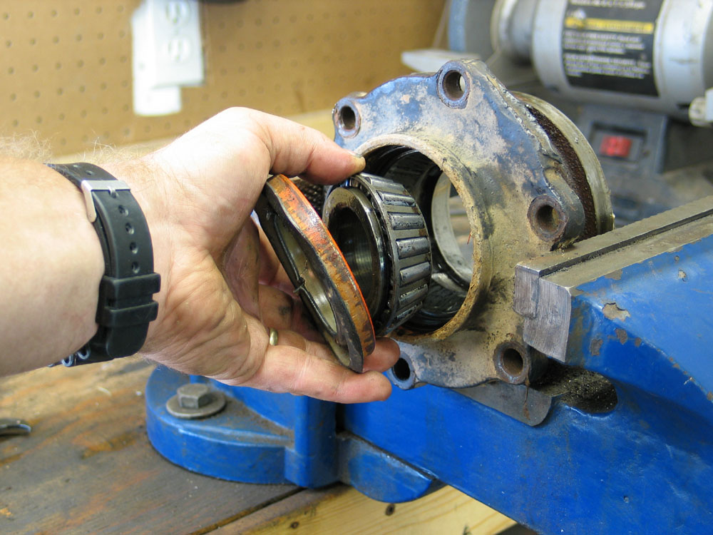
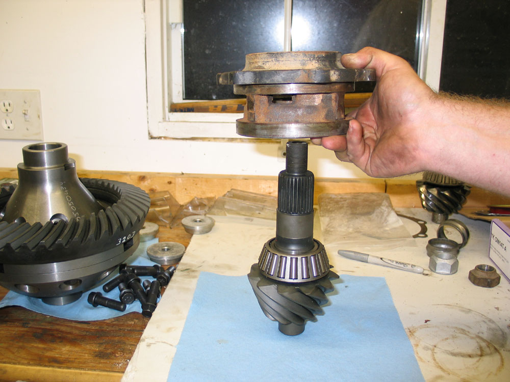
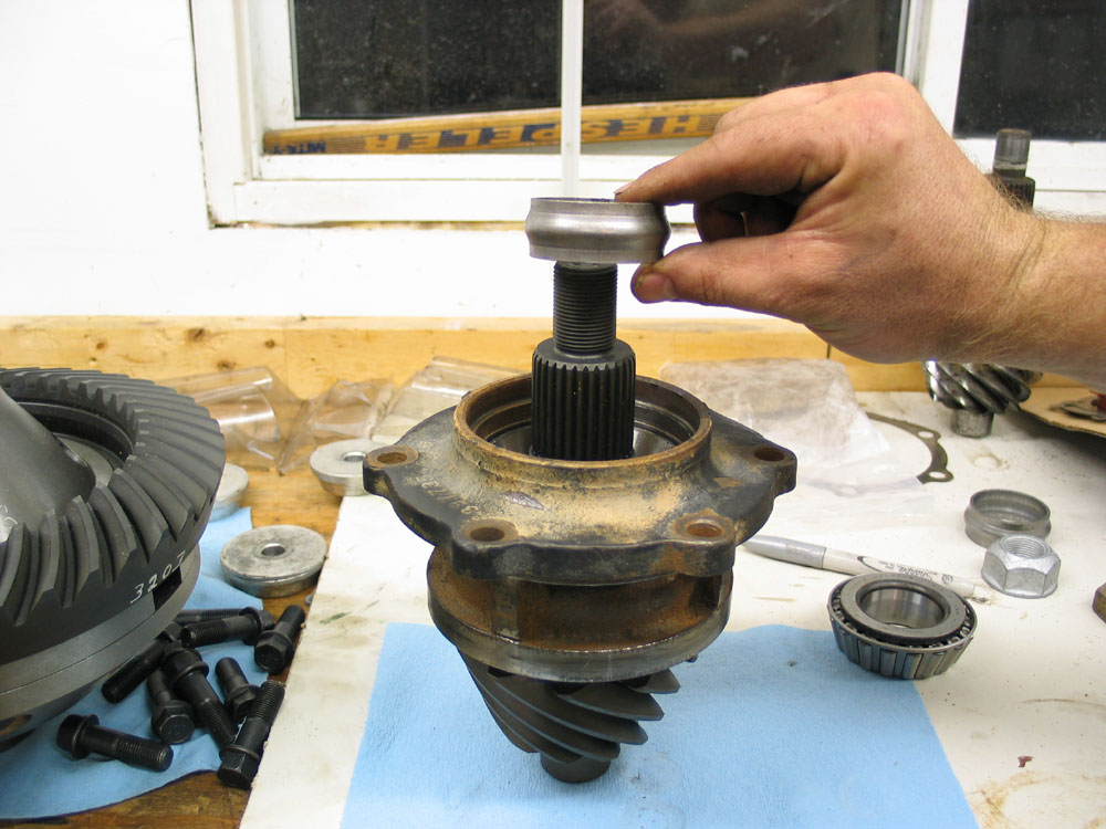
Once removed, the pinion bearing retainer assembly looks like this. | |||||||||||||||||||||||||||||||||||||||||||
 |
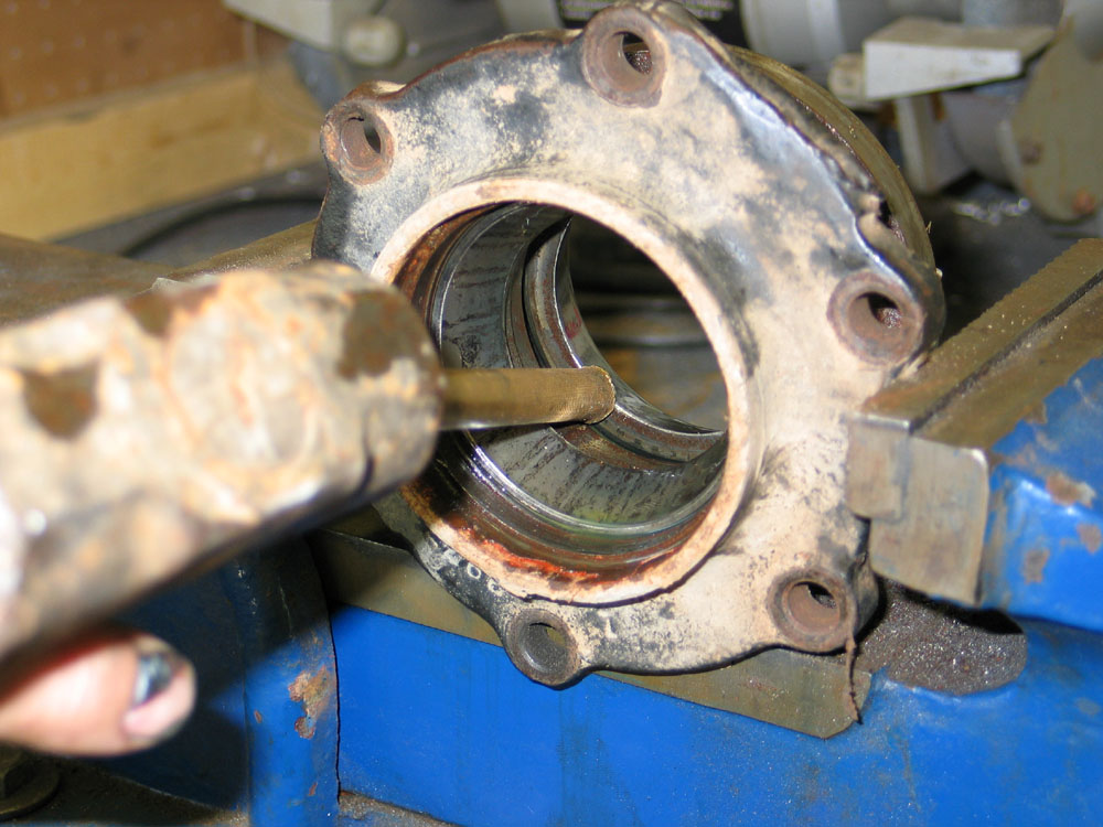
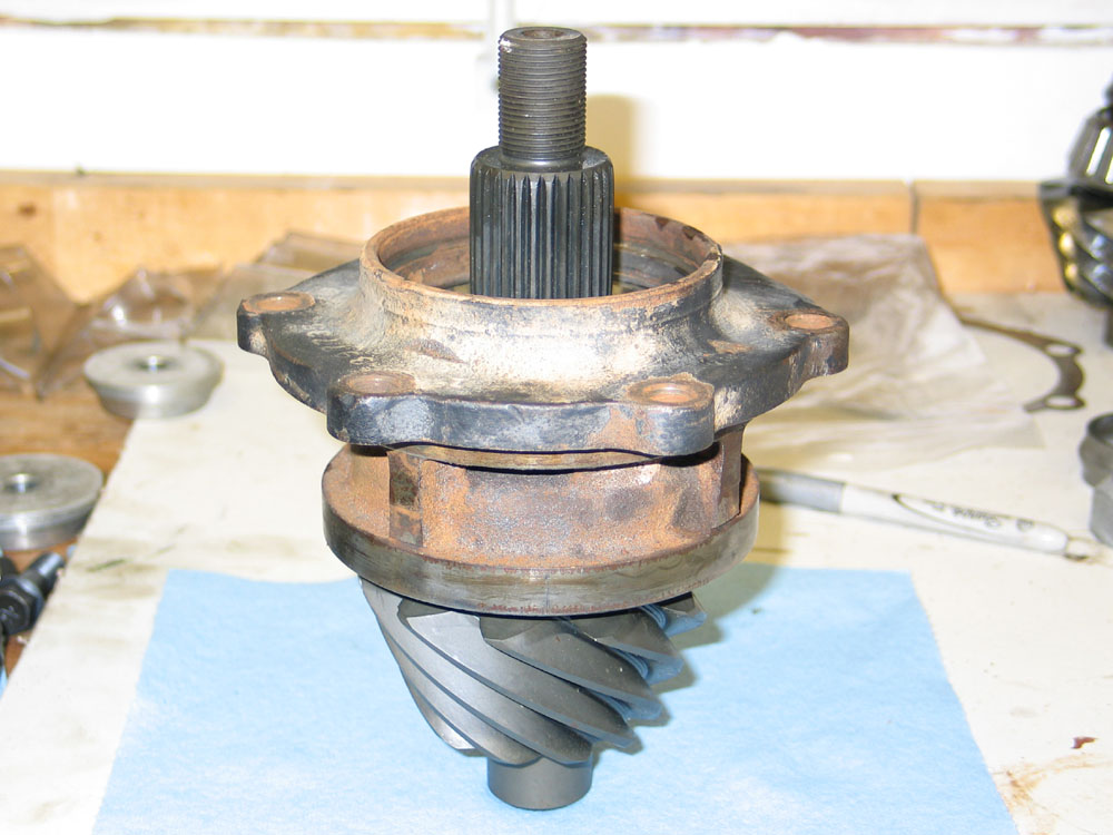
View from the rear of the pinion bearing retainer with pinion installed. |
|||||||||||||||||||||||||||||||||||||||||||
 |
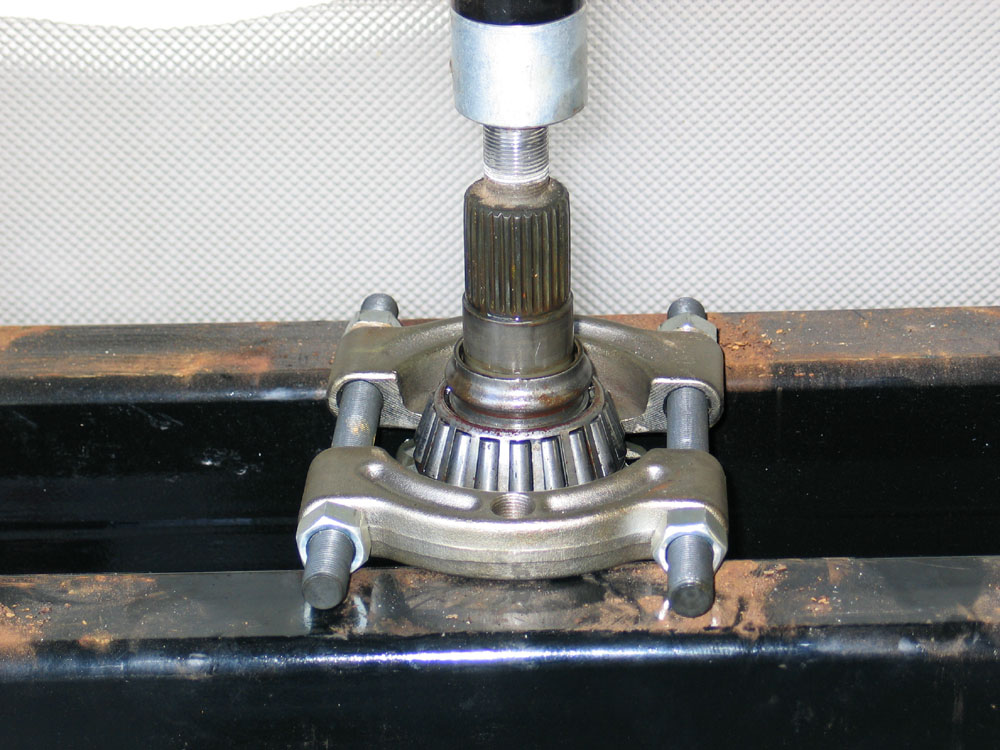
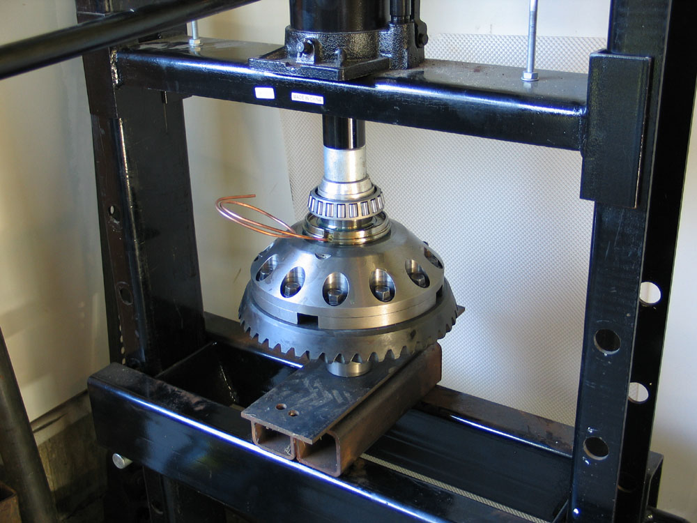
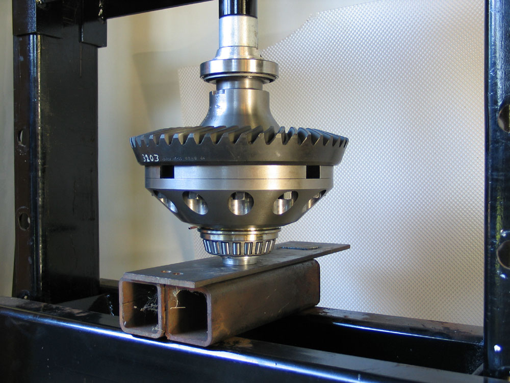
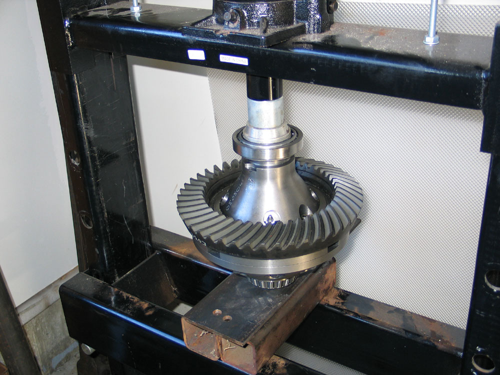
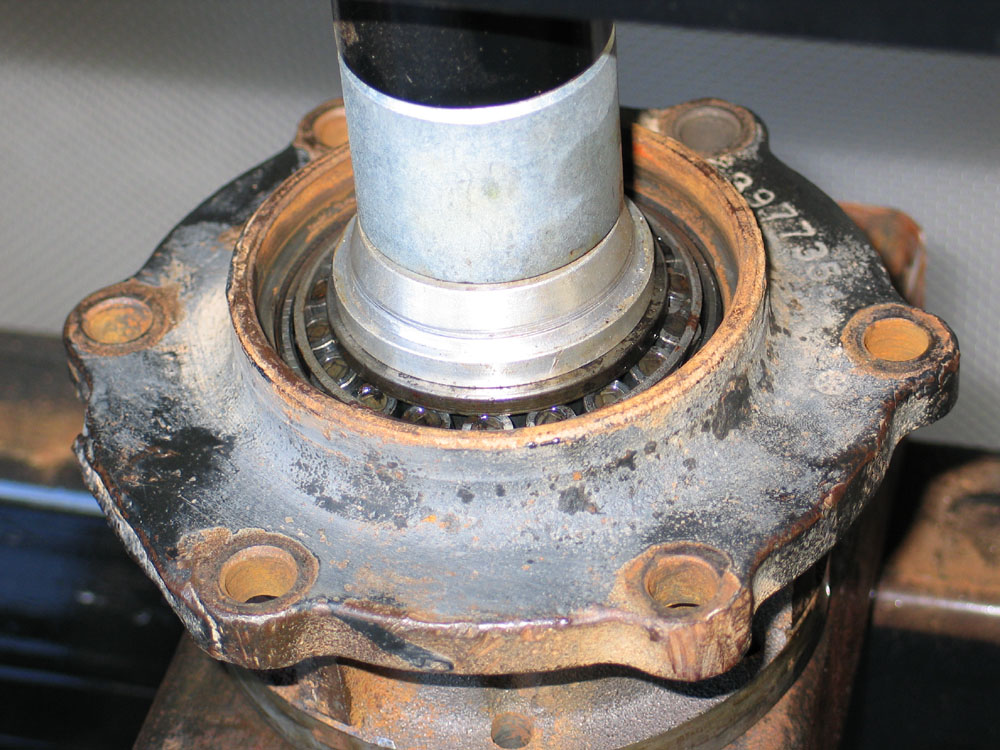
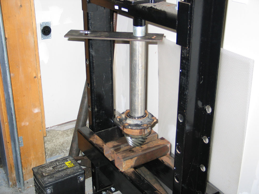
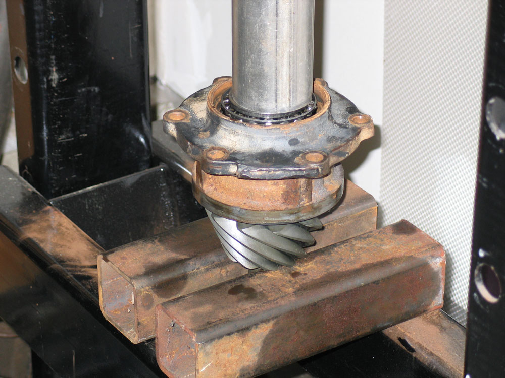
I used a small 20-ton shop press to press the pinion out of the yoke and bearing retainer. If you ever want to re-use the pinion, be sure to get the press nice and square and either use a soft end-cap or a brass plug in between the press and pinion threads to avoid damaging the threads. Also, have a box with rags in it, or something similar, for the pinion to fall into when it pops out - otherwise it will smash into the concrete shop floor and likely damage the straddle bearing journal and/or pinion teeth... ...don't ask! |
|||||||||||||||||||||||||||||||||||||||||||
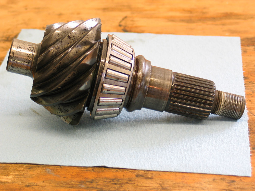 |
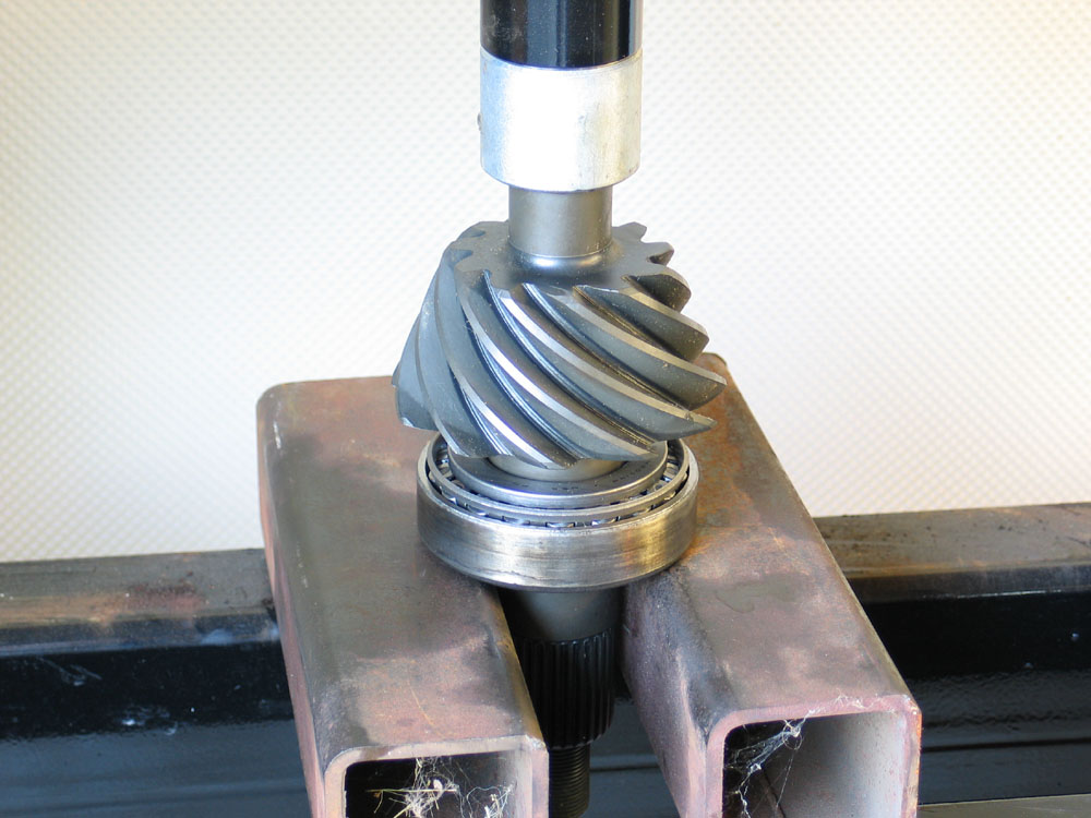
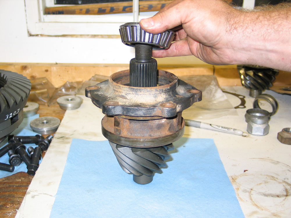
Here's what the pinion looks like when removed from the bearing retainer | |||||||||||||||||||||||||||||||||||||||||||
 |
A view from the rear of the bearing retainer, with the rear pinion bearing race closest to the camera. The 14-Bolt pinion bearing retainer is a unique and clever beast. It's really just a housing that holds the races for the two pinion bearings - but what it allows you to do is set up the pinion before assembling it into the axle housing. Also, because it holds the pinion and is removable from the axle housing - it means pinion depth can be controlled simply by shimming this retainer when it's installed into the axle housing. This means shims are not needed on the pinion itself, under the bearings, to set depth; and therefore you don't need set-up bearings and you don't need to remove and install bearings and shims to adjust pinion depth. Simply pull the retainer, add or subtract shims between it and the axle housing, and re-install. |
|||||||||||||||||||||||||||||||||||||||||||
 |
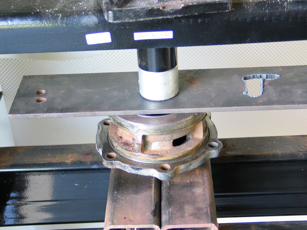
To remove the rear pinion bearing and old crush sleeve I used a large bearing separator and the press. Once again - be careful not to damage the threads on the pinion and place something underneath to catch the pinion when it falls. |
|||||||||||||||||||||||||||||||||||||||||||
 |
With the pinion removed, it's time to remove the seal and races from the bearing retainer. Clamp the retainer securely in a vice. I used a seal-pulling-sharp-pointy-like-thing* tool to remove the seal. It's probably in there fairly tight, and you're likely to ruin it getting it out.
* Note: probably not the real name. |
|||||||||||||||||||||||||||||||||||||||||||
 |
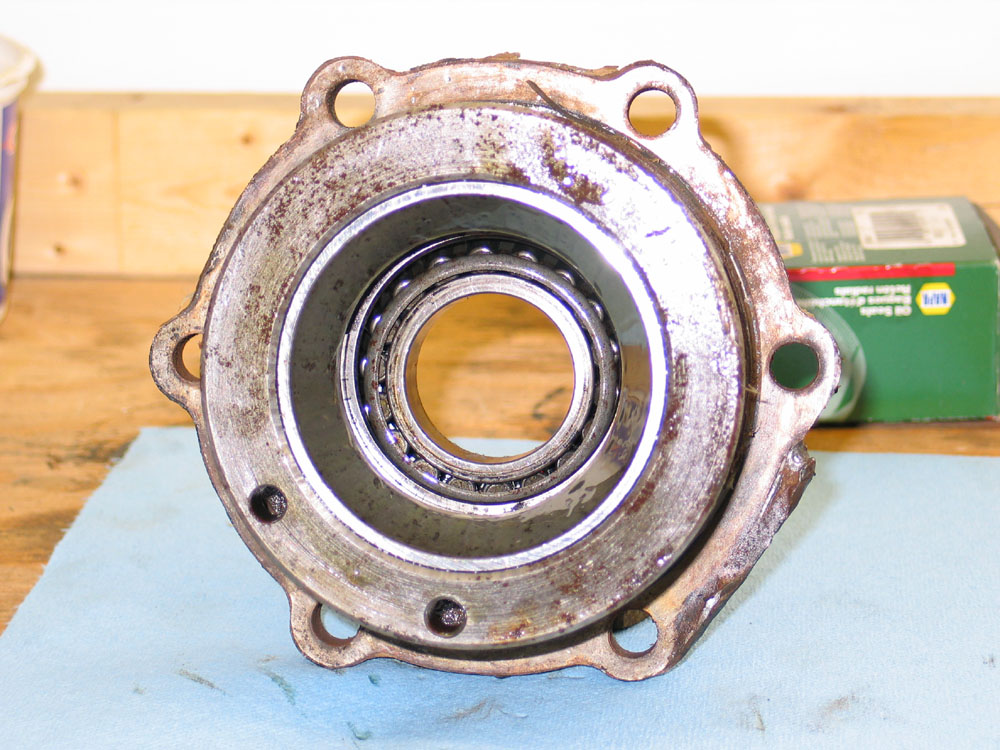
With the seal removed, the front pinion bearing cone slides out. | |||||||||||||||||||||||||||||||||||||||||||
 |
You are left with the retainer with just the two races installed. Nice corrosion on that race - no wonder preload was so out of spec! |
|||||||||||||||||||||||||||||||||||||||||||
 |
Use a brass drift and a hammer to knock out each race from behind. Oops - looks like I missed at least once and hit that thumb! With both races removed, give the retainer a thorough cleaning. Make sure no oiling passages are blocked, and pay particular attention to ensuring that the back face of the mounting flange (where the pinions shims go) is flat and true. Mine had some rough edges where the extreme outside edge had gotten rock-rash so I cleaned them up with a small machinist's hand file. |
|||||||||||||||||||||||||||||||||||||||||||
 |
The final step in disassembly is to remove the straddle bearing from the axle housing. I used the trusty hammer and a large deep socket to carefully drive it out. That poor thumb's not getting any better! |
|||||||||||||||||||||||||||||||||||||||||||
Reassembling Carrier and Ring Gear |
||||||||||||||||||||||||||||||||||||||||||||
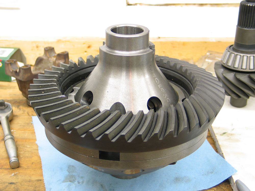 |
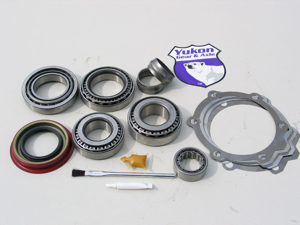
The first step in reassembly is to install the new ring gear on the carrier. I used a new set of Yukon 4.11 gears and installed them on the new 14-Bolt ARB Air Locker. If you are re-using an old ring gear be sure to clean it thoroughly before installing it on the carrier. Pay particular attention to ensuring the mounting surface is clean and burr-free and that all the bolt holes are clean, free from any grease or old thread-locking compound, and dry. Ensure that the ring gear mounting flange on the carrier is similarly clean and dry. Heat the ring-gear in a kitchen stove at 200°F for about 45 minutes to expand it slightly and ease assembly. Note that this step is recommended only for new, clean gears - unless of course your spouse doesn't mind the aroma of baking gear oil! Never heat the ring gear with a flame as this will damage the hardened surfaces. In a pinch, you could heat an old ring gear in boiling water on a camp stove or the like. |
|||||||||||||||||||||||||||||||||||||||||||
If you're reusing the old carrier and/or ring gear, ensure the parts are re-assembled in their original positions by using the alignment marks you made earlier. Carefully install the ring gear onto the carrier, tapping with a soft-faced hammer if necessary, being sure to line up the bolt holes. DO NOT use the bolts to pull the ring gear onto the carrier as this will damage the ring gear bolts. |
||||||||||||||||||||||||||||||||||||||||||||
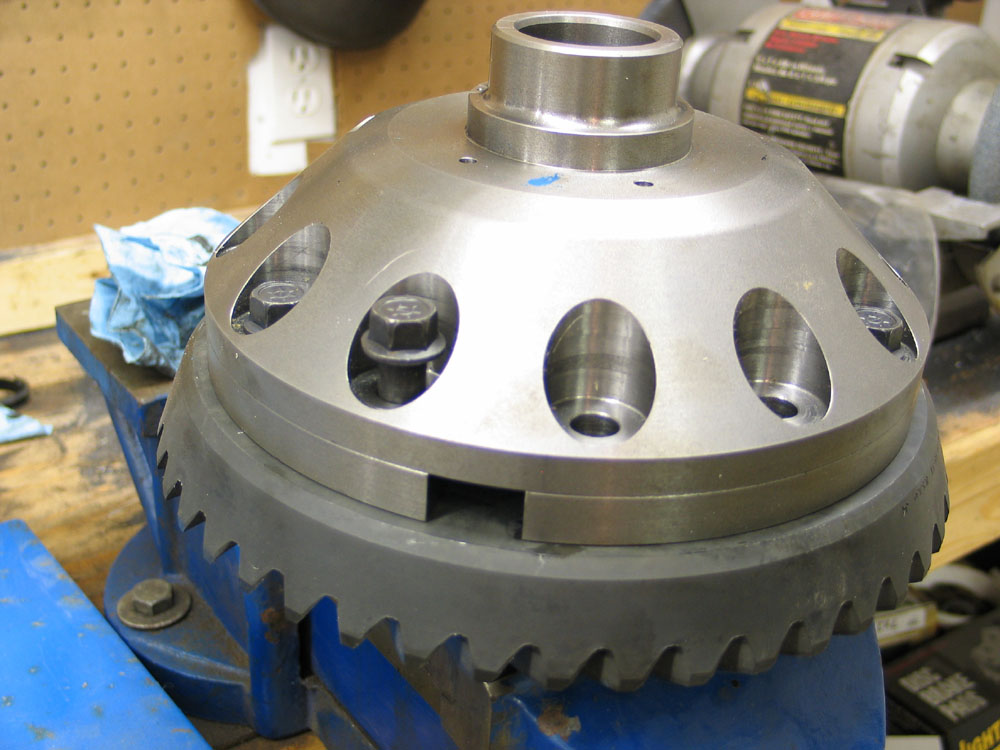 |
Apply a little high-strength thread locking compound to the ring gear bolts and carefully insert them. Don't go overboard with the thread locker - only a little is needed. I find the new gel kind from Loctite works very well. ALWAYS install new ring gear bolts - even if reusing the carrier and/or ring gear. Torque the ring gear bolts evenly, in two or three stages, using a crosswise pattern, to 120 ft/lbs. You will have to carefully clamp the carrier in a vice to do this - using a rag or something similar to prevent damage to the carrier. |
|||||||||||||||||||||||||||||||||||||||||||
Also, be aware that most master install kits for the 14-Bolt will not include ring gear bolts - they have to be ordered separately. There are also two different length bolts available - the correct one depends on the gear ratio being used. Bolts for the 4.11 and down carrier are 1.8" long and bolts for the 4.56 and up carrier are 2.1" long. Note that neither length is the same as any standard SAE bolt. Obviously, since a different part is required for each, and with such a small difference, the exact length of thread engagement of the bolt into the ring gear is critical. For more information and pictures, check out my Yukon 14-Bolt gears and master install kit review. |
||||||||||||||||||||||||||||||||||||||||||||
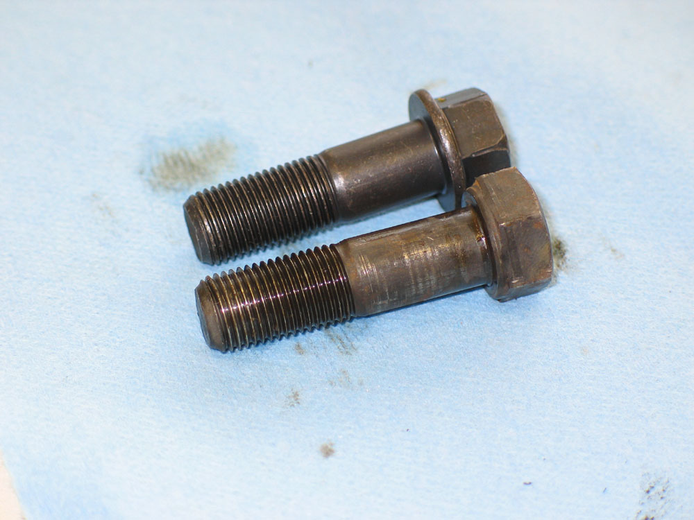 |
This pic shows a replacement ring gear bolt for a 4.11 carrier on top, with original part, minus the lock washer, below. Depending on the year, original 14-Bolt ring gear bolts may use split lock washers. Personally, I don't like split lock washers and prefer to avoid them if at all possible (see my Nuts & Bolts article for reasons why); and my opinion wasn't altered any when I found four or five cracked in half upon disassembling my original carrier. As such, I was pleased to discover that the replacements from Randy's don't use them, and are a flanged design instead. If you are using stock-style ring gear bolts that originally used a spit washer, you must also replace the washers with new ones. If you delete the lock washers - the bolts will be too long, as illustrated in the pic at left. |
|||||||||||||||||||||||||||||||||||||||||||
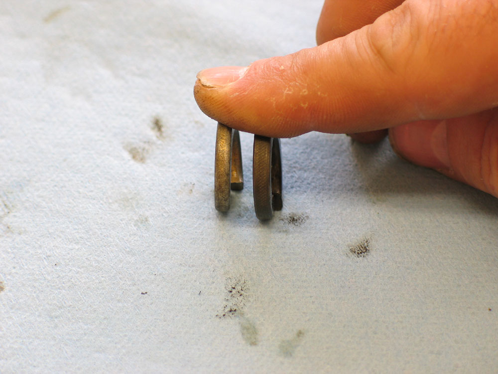 |
The final thing to watch for is that the stock lock washers are much thicker than standard SAE pieces. The pic at left shows a standard SAE 9/16" grade 8 hardened lock washer on the left, and a stock 14-Bolt ring gear bolt lock washer beside it. You may find that sourcing the correct replacement lock washers is difficult or ridiculously expensive (from a GM dealer). In the end, your best bet is probably just to order a set of new, replacement bolts from a reputable vendor like Randy's Ring & Pinion. Be sure to order for the correct gear ratio. |
|||||||||||||||||||||||||||||||||||||||||||
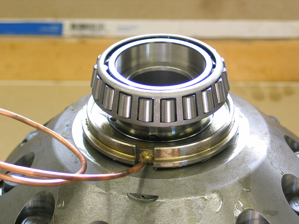 |
With the ring gear installed, place the carrier on the bench and install the carrier bearings. Install the left (non ring gear side) bearing first. Carefully place the bearing cone square on the journal. |
|||||||||||||||||||||||||||||||||||||||||||
 |
Then press it into place until the bearing seats firmly against the shoulder of the bearing journal. I found that the bearing seated before the driver I was using bottomed on the carrier journal. | |||||||||||||||||||||||||||||||||||||||||||
 |
The right side is just a little more tricky since you already have a bearing installed on the opposite side. This is because the rollers and cage protrude slightly above the end of the carrier. If you were to simply set the carrier on the press bed and press on the right side bearing, you would damage the cage of the other bearing, ruining it. To avoid this, I placed a small driver underneath the carrier that fit inside the ID of the bearing, against the end of the journal. This way, the load will transmit through the carrier journal to the driver, to the press, without damaging the installed bearing. |
|||||||||||||||||||||||||||||||||||||||||||
 |
I then pressed on the bearing, making sure the driver bore only against the inner ring of the bearing cone, and not against the cage or rollers. | |||||||||||||||||||||||||||||||||||||||||||
Reassembling the Pinion |
||||||||||||||||||||||||||||||||||||||||||||
 |
With the carrier assembled you can move on to the pinion. The first step is to install the new pinion races into the bearing retainer. I used the press and a scrap of steel plate to initially press the rear race into the retainer. However, to seat fully, the edge of the race has to be below the retainer. I finished the last fraction of an inch by placing an old bearing in the race and pressing on the centre of the bearing. |
|||||||||||||||||||||||||||||||||||||||||||
 |
I used the same "old-bearing" technique to seat the front race, as it sits in the retainer quite a distance below the edge of the retainer. In the pic you can see I've placed a small aluminum seal driver between the end cap of the press and the bearing. |
|||||||||||||||||||||||||||||||||||||||||||
 |
A nice thing about the 14-Bolt design is that, unlike a Dana axle, there are no baffles, slingers, or shims on the pinion to worry about. Also, because pinion depth is controlled by shims between the bearing retainer and the axle housing, there's no need to make or install set-up bearings - you just go straight ahead and install the new bearings. Install the rear pinion bearing cone onto the pinion. I placed the race on the cone, then used the press and a couple of pieces of square tubing to support the race either side of the pinion, then pressed carefully on the straddle bearing journal. |
|||||||||||||||||||||||||||||||||||||||||||
 |
With the rear pinion bearing in place on the pinion, place the completed bearing retainer onto the pinion... | |||||||||||||||||||||||||||||||||||||||||||
 |
...and it looks like this | |||||||||||||||||||||||||||||||||||||||||||
 |
Slide the crush sleeve onto the pinion shaft. | |||||||||||||||||||||||||||||||||||||||||||
 |
Then place the front pinion bearing cone over the pinion shaft and into the bearing retainer. | |||||||||||||||||||||||||||||||||||||||||||
 |
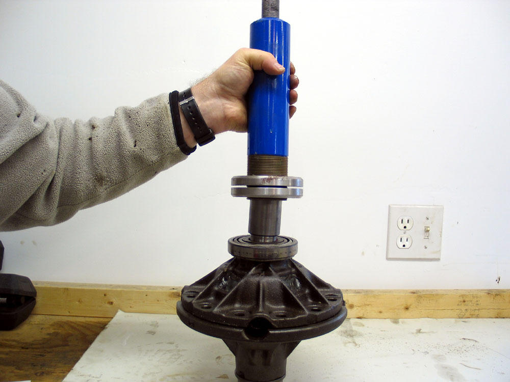
The next step is the trickiest part of the whole procedure. You need to press the front pinion bearing cone onto the pinion shaft, seating it in its race, without crushing the crush sleeve too much. In order to get over the pinion shaft you'll need to use a tube to bear on the inner ring of the bearing cup. Here I'm using an old piece of 3" exhaust tube. |
|||||||||||||||||||||||||||||||||||||||||||
 |
You want to seat the bearing firmly, and even begin crushing the sleeve a little to begin setting pinion bearing preload. This can save time and effort later when you are tightening the pinion nut to crush the sleeve and set final preload. However, you don't want to go too far. If you crush the sleeve too much at this point, you will find that later, when you go to tighten the pinion nut, bearing preload will be achieved before you get the pinion nut tight enough (once again - don't ask how I know this!) On the other hand, if you just press the bearing on loosely, and don't even begin to crush the sleeve, you can have a hell of a job later, trying to start the sleeve crushing by tightening the pinion nut. I've heard reports of it taking upwards of 500 ft/lbs - which requires a heck of an impact gun or a seriously sturdy bench/vice and a BIG breaker bar. |
|||||||||||||||||||||||||||||||||||||||||||
The trick is to use the press to seat the bearing and just start the sleeve crushing. Once the sleeve has started crushing - it takes a lot less torque on the pinion nut to continue crushing it. Like crushing a beer can in you hands - once it starts buckling it's much easier. The best method is to press a little at a time and check frequently how tight the bearing is in its race. Once again - too far, and you'll find yourself later at max bearing preload with the pinion nut torqued to only 100 ft/lbs - which isn't really tight enough to keep it tight. If you do cock it up - you'll have to press the pinion out of the crush sleeve and front bearing cone, install a new crush sleeve, and start again. |
||||||||||||||||||||||||||||||||||||||||||||
 |
With the front bearing pressed in place, coat the lips of the pinion seal with extreme pressure grease, and place it over the pinion and into the retainer. | |||||||||||||||||||||||||||||||||||||||||||
 |
Tap the seal into place with a mallet, being careful not to damage it. It's a tight fit. | |||||||||||||||||||||||||||||||||||||||||||
 |
Place the yoke on the pinion shaft splines... | |||||||||||||||||||||||||||||||||||||||||||
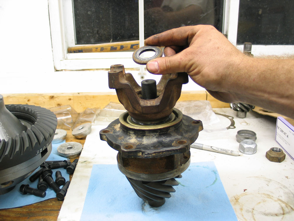 |
...install the pinion nut washer... | |||||||||||||||||||||||||||||||||||||||||||
 |
...and install a brand new pinion nut. | |||||||||||||||||||||||||||||||||||||||||||
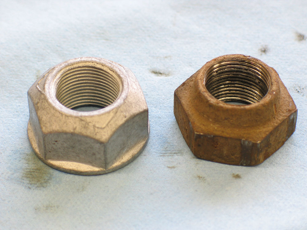 |
I don't care what anybody else says - never re-use an old pinion nut - always use a new one. They are deformed-thread style locking nuts that play a critical role. Not only does it have to be tight and stay-tight to keep the pinion where it should be, but because of the crush sleeve design - you're going to use this nut to set pinion bearing preload. Imagine the stress in the threads when you're doing this and cranking that nut down to three or four hundred ft/lbs! If that doesn't convince you - enlarge the picture at left and look at the threads of an old nut compared to a new. |
|||||||||||||||||||||||||||||||||||||||||||
 |
I spun the pinion nut on until it was just snug using an impact gun on low and a 1.5" socket. | |||||||||||||||||||||||||||||||||||||||||||
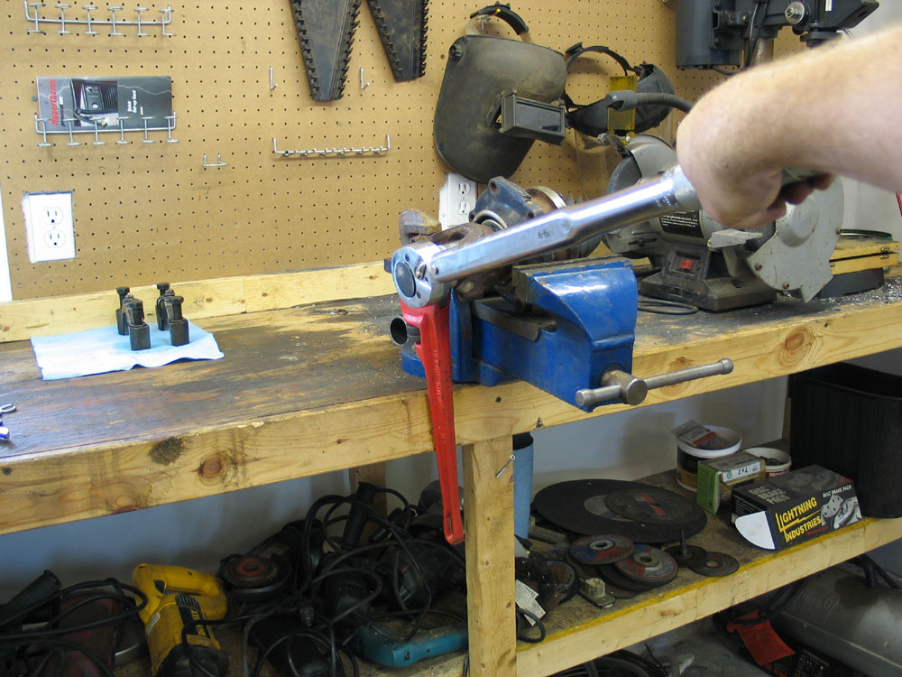 |
I then reverted to a 3/4"-drive torque wrench to do the final tightening. Here you can see the bearing retainer clamped securely in a vice (make it tight!) with a pipe wrench on the yoke jammed against the bench to prevent the pinion from turning. Tighten the pinion nut initially to 300-350 ft/lbs, then remove the torque wrench and yoke holder and take a reading of the torque required to rotate the pinion, using your in/lb torque wrench just as you did on disassembly. Proper pinion bearing preload is achieved when the torque required to rotate the pinion is 5-15 in/lbs for used bearings or 25-35 in/lbs for new bearings. |
|||||||||||||||||||||||||||||||||||||||||||
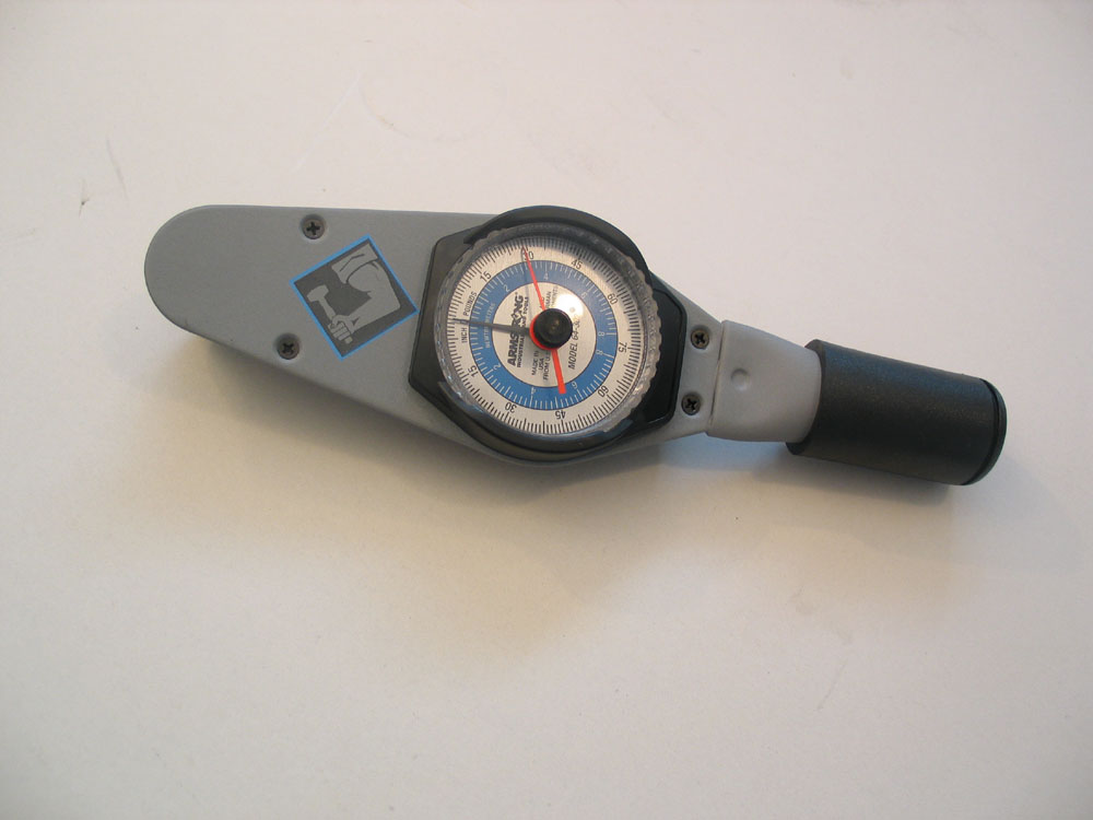 |
The best tool for checking pinion bearing preload, on any axle, is a dial-indicating torque wrench with a fairly small scale. This particular unit is an Armstrong 1/4' drive 0-75 in/lbs model. It also has a red indicator needle for recording the maximum value attained. Remember though - it's the torque to keep the pinion rotating that you want to measure and record - not the initial torque it takes to get it turning (which, typically, can be anywhere from 10-30 in/lbs higher). |
|||||||||||||||||||||||||||||||||||||||||||
Installing the Pinion |
||||||||||||||||||||||||||||||||||||||||||||
 |
First, install the new pinion straddle bearing into the housing by driving it in from the front until is seats firmly. Oh look - I haven't managed to smash that thumb with the hammer yet! |
|||||||||||||||||||||||||||||||||||||||||||
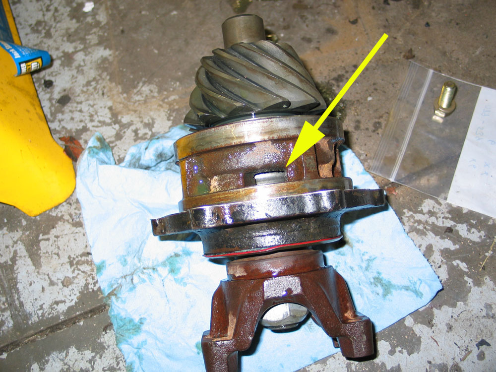 |
Insert the pinion bearing retainer, with pinion installed, into the axle housing. At this point I just re-used the original pinion depth shim between the retainer and axle housing as I like to set backlash before worrying about pinion depth. When installing the bearing retainer, make sure that the oiling port on the retainer (yellow arrow) matches up with... |
|||||||||||||||||||||||||||||||||||||||||||
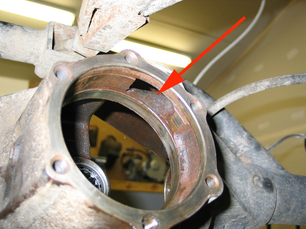 |
...the oiling galley in the axle housing (red arrow). Strangely, no manual I have ever read mentions this - which is strange because the bolt pattern is symmetrical, meaning you could overlook this step and still install the retainer in the housing...with predictably disastrous results! Don't ask! |
|||||||||||||||||||||||||||||||||||||||||||
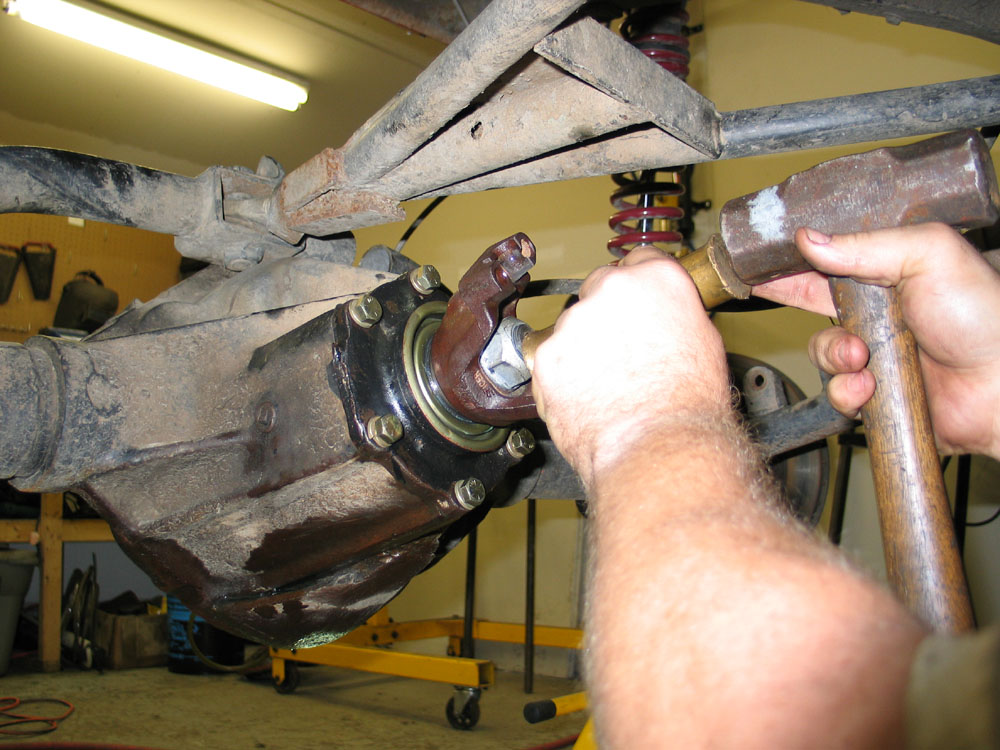 |
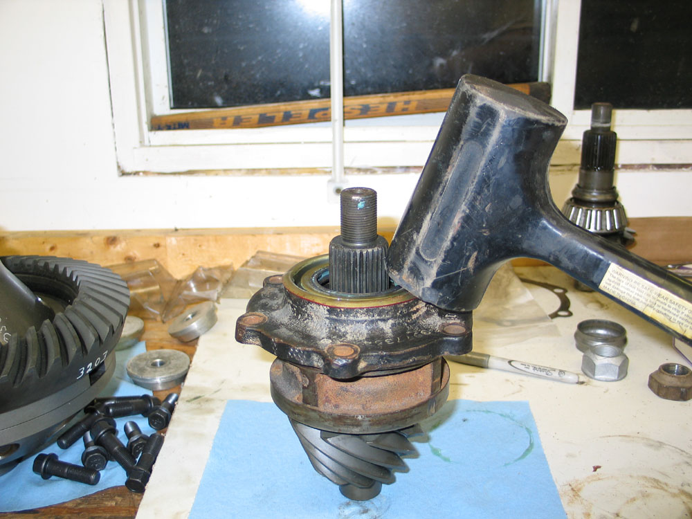
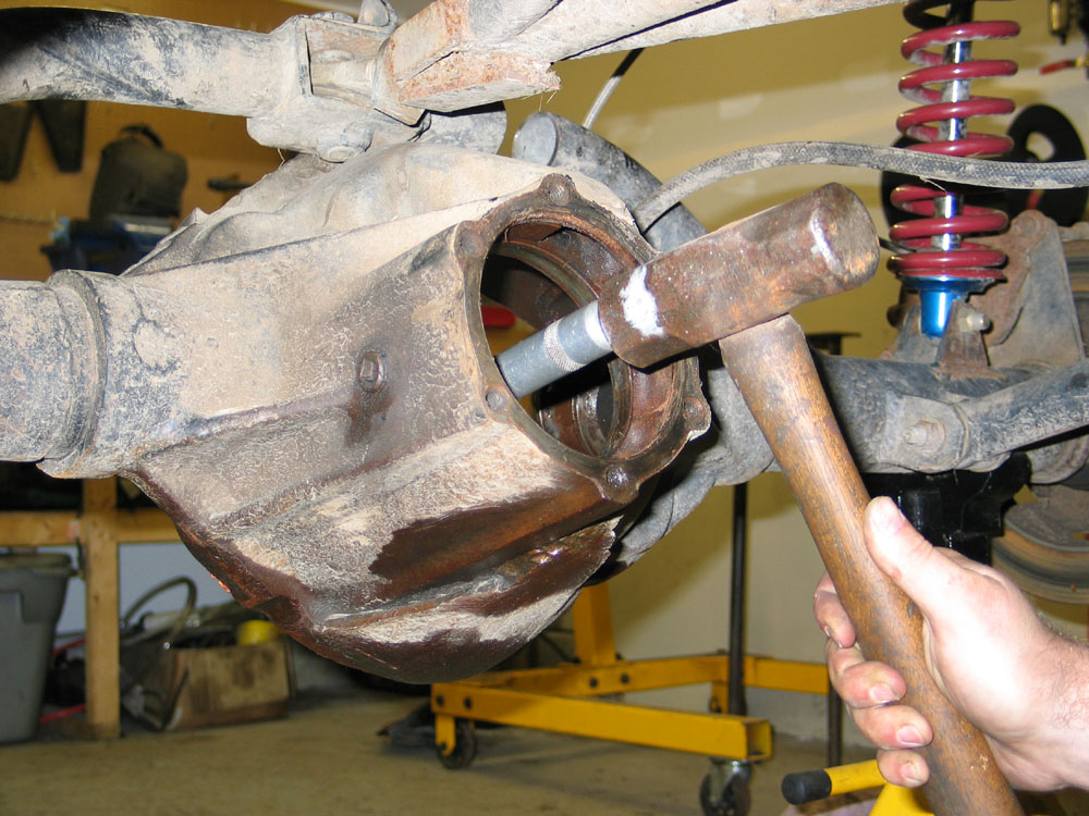
When installing the pinion bearing retainer assembly into the axle housing, the journal on the head of the pinion will have to be driven into the bore of the straddle bearing. It's a tight fit but shouldn't require you to pound it in. Use a brass drift on the end of the pinion to tap the retainer and pinion into place. |
|||||||||||||||||||||||||||||||||||||||||||
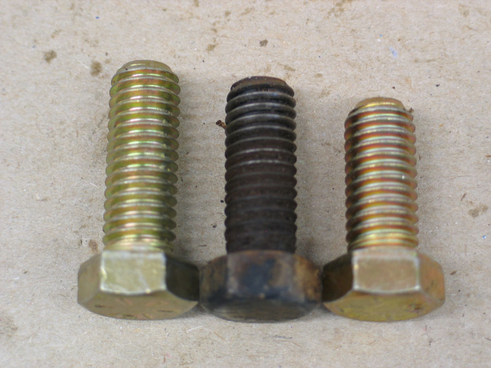 |
Install the six bearing retainer bolts and lock washers and torque in a crosswise pattern to 65 ft/lbs. Of note, the stock 3/8-NC16 bolts used to secure the pinion bearing retainer to the axle housing (middle) are neither 3/4" nor 1" in length. I wanted to replace mine, so I checked the depth of the tapped blind holes in the axle housing and discovered that the longer 1" bolts work fine without bottoming. |
|||||||||||||||||||||||||||||||||||||||||||
Installing Carrier into Housing and Setting Backlash and Carrier Preload |
||||||||||||||||||||||||||||||||||||||||||||
 |
With the carrier bearing races installed, place the carrier in the axle housing. Using the punch marks made earlier, install the carrier bearing caps in their original positions and tighten them until just snug. Over tightening them at this point will freeze the carrier bearings in their bores and interfere with setting carrier preload. Loosen the right-side adjusting nut and tighten the left-side adjusting nut until the ring gear contacts the pinion without binding. This is zero backlash. |
|||||||||||||||||||||||||||||||||||||||||||
 |
Back off left-side adjusting nut approximately 2 slots. Install left-side adjusting nut lock, washer, and bolt. Tighten bolt to 20 ft/lbs. Tighten right-side adjusting nut until carrier is forced into solid contact with left-side adjusting nut. Loosen right-side adjusting nut until it is free from bearing contact, then re-tighten until contact is re-established. Now tighten right-side adjusting nut two slots if carrier bearings are reused or three slots if carrier bearings are new. Install right-side adjusting nut lock, washer, and bolt. Tighten bolt to 20 ft/lbs. Tighten bearing cap bolts to 135 ft/lbs. |
|||||||||||||||||||||||||||||||||||||||||||
The carrier bearings are now properly preloaded. After this step, if one adjusting nut is loosened, the other must be tightened an equal amount to maintain carrier bearing preload. Backlash should now be checked at a minimum of two different places on the ring gear. The dedicated will check backlash in four equally spaced places, and the truly devout will measure the axial run-out of the ring-gear, mark the high, low, and average spots, and use them to measure backlash. |
||||||||||||||||||||||||||||||||||||||||||||
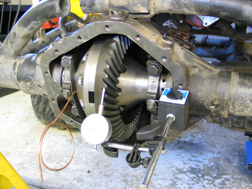 |
Whichever method you choose, read the backlash as follows: 1. Install dial indicator on the axle housing so that it is as perpendicular as possible to the ring-gear tooth. You want to place the button against the top-heel of the tooth, and arrange it so that the shaft is as close as possible to 90 degrees to the tooth at that point 2. Hold pinion steady, rotate ring-gear as far as it will go, check indicator button is against tooth, set indicator to 0 3. While holding pinion steady, rotate ring-gear as far as it will go in the opposite direction and take reading. |
|||||||||||||||||||||||||||||||||||||||||||
Backlash should be between .003" - .012", with .005"-.008" preferred, and with no variance greater than .002. If you cannot get consistent readings it is advisable to use the dial indicator to check the axial and lateral run-out of both the ring-gear and the carrier mounting flange to determine where the problem lies. If neither exhibits run-out of greater than .002"-.003" the problem may lie in a bent housing |
||||||||||||||||||||||||||||||||||||||||||||
| My technique was to rotate the yoke until I could hook the fingers of my right hand around the ears of the yoke and lock the yoke in place with the heel of my palm against the housing. I then installed the dial indicator with the shaft compressed a little, knelt in front of the housing, grasped the yoke with my right hand as described, then used my left hand to grasp the head of a ring gear bolt and used it to turn the ring gear as far as it would go one way. Keeping pressure on the ring gear with a couple of fingers on the ring gear bolt head, I then used thumb and finger on my left hand to rotate the dial indicator to zero. Then, still keeping my right hand locking the pinion from turning, I rotated the ring gear the opposite way using the ring gear bolt head while observing the dial indicator and reading the backlash. Using this method I was able to rock the ring gear back and forth by the ring gear bolt head while observing the dial indicator to ensure a consistent, accurate measurement of the backlash.
If backlash is not within spec, adjustments are made with the adjusting nuts as follows: 1. Remove the adjusting nut locks, washers, and bolts and set aside. 2. Loosen the carrier bearing cap bolts until they are just snug. 3. If backlash is more than .012", loosen right-side adjusting nut one slot and tighten the left-side adjusting nut one slot. 4. If backlash is less than .003", loosen left-side adjusting nut one slot and tighten the right-side adjusting nut one slot. 5. Re-check backlash with the dial indicator as above. 6. When backlash is correct, re-install adjusting nut locks and re-torque bearing cap bolts. Remember that the right adjusting nut is loosened by moving the screwdriver handle DOWN - the left adjusting nut is loosened by moving the screwdriver handle UP. Setting Pinion Depth |
||||||||||||||||||||||||||||||||||||||||||||
 |
In the 14-Bolt, pinion depth is controlled by shimming the pinion bearing retainer. The shims are shown at the far right in this pic. | |||||||||||||||||||||||||||||||||||||||||||
.jpg) |
The shims are placed between the mounting flange of the bearing retainer (blue arrow)... | |||||||||||||||||||||||||||||||||||||||||||
.jpg) |
...and the mounting surface on the axle housing (blue arrow). | |||||||||||||||||||||||||||||||||||||||||||
In order to set pinion depth, calculate a starting shim stack (a shim stack is the total thickness of one or more shims used together), install it, check the gear contact pattern, and then adjust the shim stack as indicated by the pattern. To determine the proper starting shim stack, proceed as follows: 1. Examine the head of the new pinion for a pinion depth code marking. Do the same for the old pinion. 2. Based on the depth codes of the two pinions, use the chart below to calculate the adjustment required to the original shim stack. If a pinion does not have a depth code, assume it to be "0" (the code, that is, not the adjustment). 3. Adjust the value of the original shim stack by the amount indicted in the chart.
Table for calculating shim adjustment from pinion depth codes:
|
||||||||||||||||||||||||||||||||||||||||||||
|
With the starting shim stack calculated, proceed as follows: 1. Ensure that mating surfaces of bearing retainer and axle housing are clean. |
|||||||||||||||||||||||||||||||||||||||||||
Checking the Contact Pattern |
||||||||||||||||||||||||||||||||||||||||||||
 |
To check the contact pattern, proceed as follows: 1. Clean ring-gear teeth and wipe any oil out of the housing. |
|||||||||||||||||||||||||||||||||||||||||||
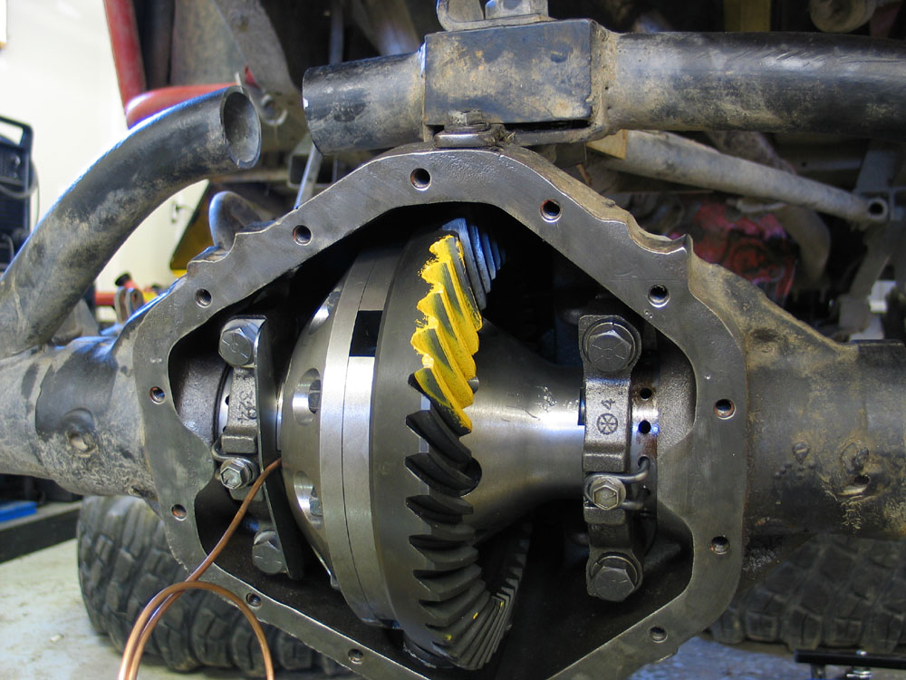
THIS NEXT STEP IS THE MOST OFTEN IGNORED STEP - AND THE #1 REASON PEOPLE HAVE TROUBLE READING THE CONTACT PATTERN In order to produce a clear, readable contact pattern you must apply a load on the gears when you rotate them. You need to apply a load so that it takes 40-50 ft/lbs of torque to rotate pinion.
It may seem a lot of trouble, but you will not get the best pattern without loading the gears, nor will you achieve optimum setup.
|
||||||||||||||||||||||||||||||||||||||||||||
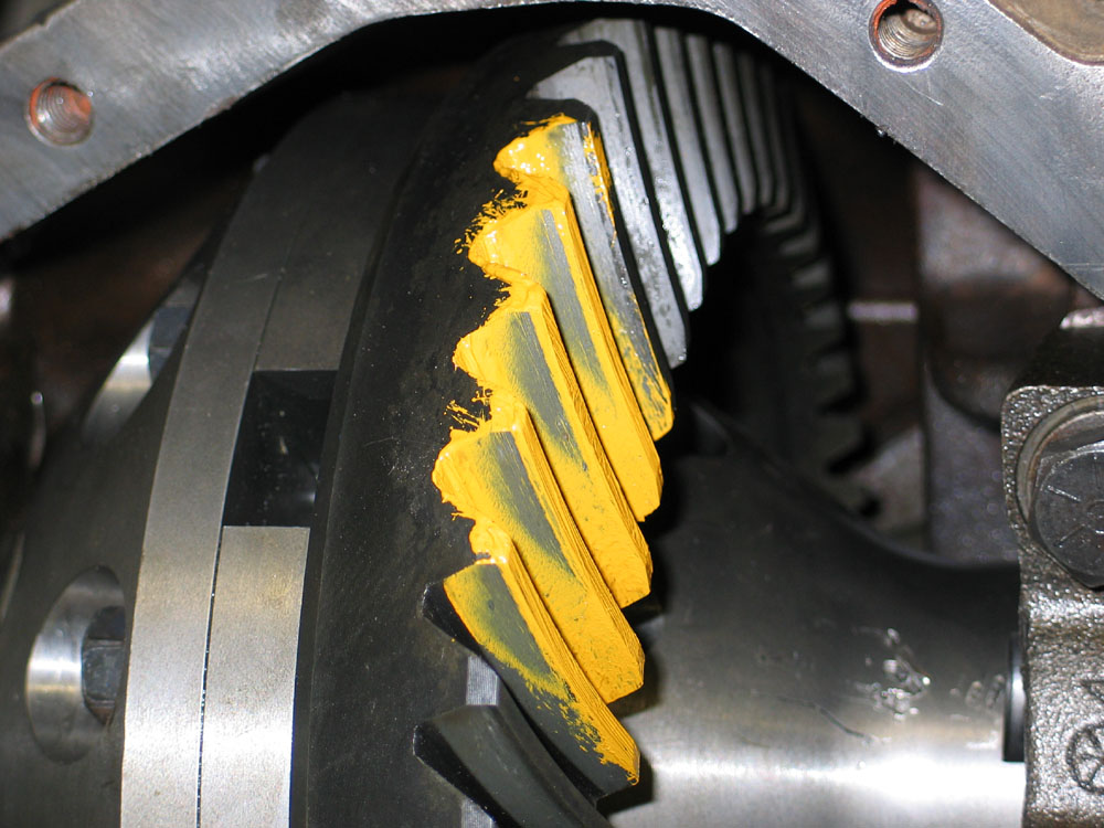 |
6. Observe and record whether the pattern is towards the top or towards the root of the ring gear teeth. Also note whether contact is at the heel or toe of the teeth. For the top - root contact check you can use either the drive or the coast side pattern, as the indication of pinion depth is the same on either side. In the case of used gears it is sometimes easier to read the coast side pattern due to wear on the gear teeth. In this picture we can see that my initial pattern displayed top/heel contact - indicating that the pinion depth needs to be increased (shims removed) and the backlash decreased slightly. |
|||||||||||||||||||||||||||||||||||||||||||
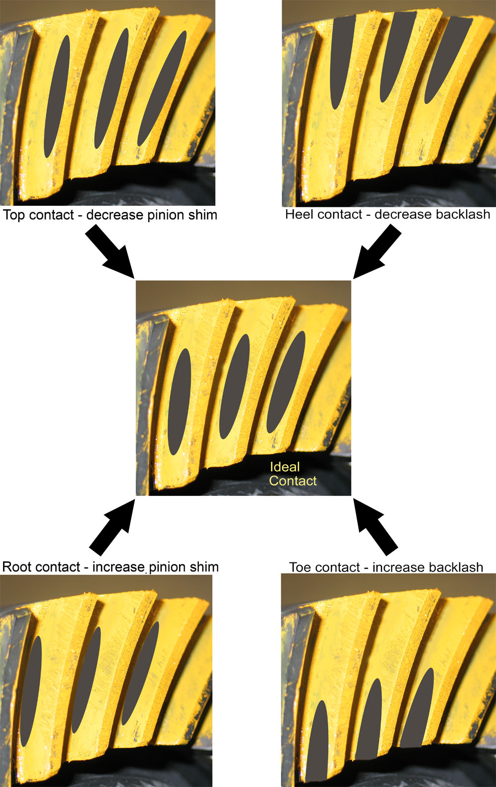
Drive Side Contact Pattern Interpretation |
Refer to the diagram at left and adjust pinion depth by adding or subtracting shims as follows:
Note that changing pinion depth also changes backlash. Increasing pinion depth (removing shims) decreases backlash; decreasing pinion depth (adding shims) increases backlash. As a result you should re-check and adjust backlash after each shim stack adjustment before re-reading the pattern. If you are having trouble juggling pinion depth and backlash, try setting backlash to the middle of the range, and then concentrating on pinion depth by concerning yourself only with the position of the pattern between the root and the toe. Once you get close to a good pinion depth pattern, re-check and re-set backlash. |
|||||||||||||||||||||||||||||||||||||||||||
Fine-tuning Overall Contact Pattern |
||||||||||||||||||||||||||||||||||||||||||||
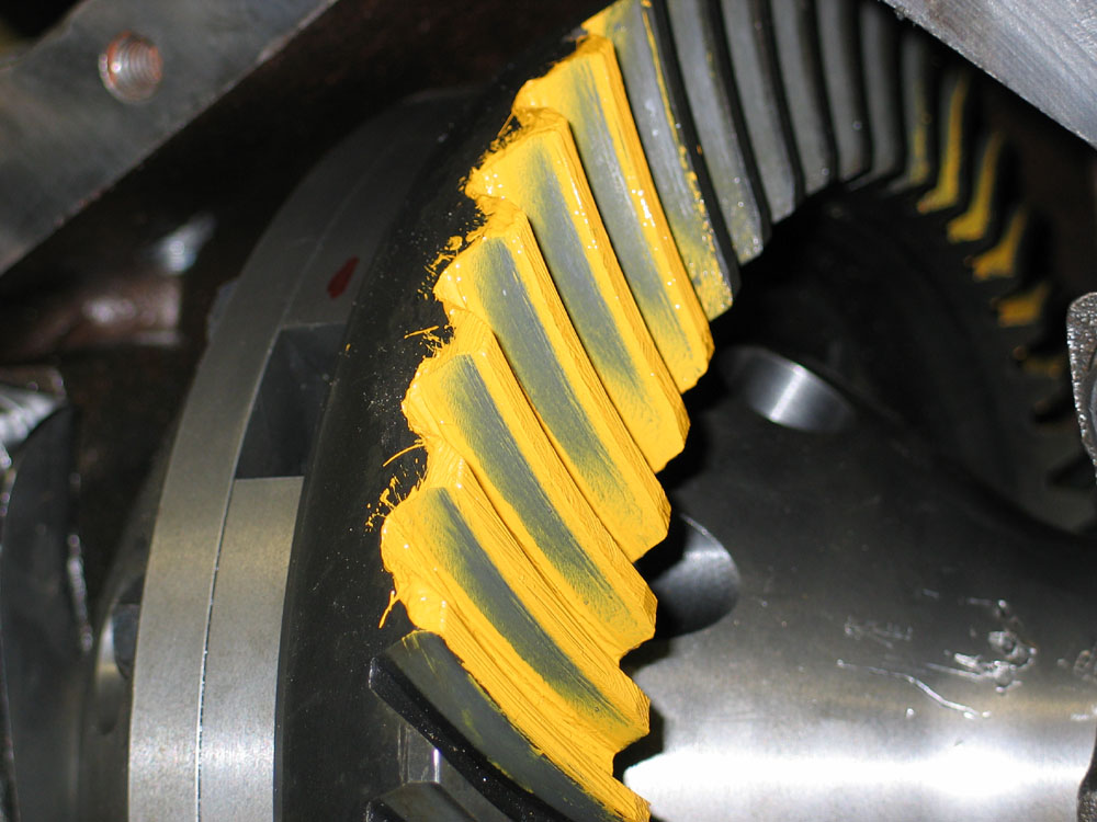 |
By the time you have adjusted the pinion depth to centre the pattern between top and root, and if you have held backlash to within spec you should have an acceptable overall contact pattern. Ultimately you are aiming for a pattern that is centred between the heel and toe and also centred between the top and root of the tooth. There should be some clearance between the pattern and the top of the tooth. On the coast-side the pattern may be slightly towards the toe. The pattern should also be broad and diffuse, without sharp edges. | |||||||||||||||||||||||||||||||||||||||||||
If, however, you are not satisfied with the location of the pattern between the heel and toe, you may be able to fine-tune the pattern further by adjusting backlash slightly while keeping it within the acceptable range. The following table summarizes the possible adjustments. Keep in mind that adjusting backlash will also affect pinion depth so that you may have to make further fine adjustments to the pinion shim stack while you home in on the perfect settings.
Finishing UpYou're almost done - the rest is easy! Apply silicone RTV compound to diff cover, install diff cover, torque cover bolts to 35 ft/lbs, and fill axle with 5.4 pints of quality hypoid gear oil, minimum GL5 rating. After all this work I wanted to ensure my new gears would be well protected in the rocks and chose to install a heavy duty diff cover from Jethro-Bilt. |
||||||||||||||||||||||||||||||||||||||||||||
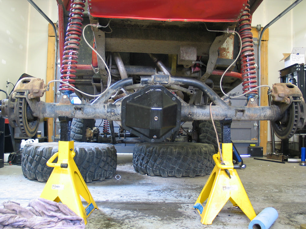 |
All that remains is to slap the axle shafts back in, torque the flange-to-hub bolts evenly in a crosswise pattern to 115 ft/lbs, reinstall the wheels, reconnect the driveshaft to the pinion yoke, lower the beast to the ground, break in the gears, and hit the trails. | |||||||||||||||||||||||||||||||||||||||||||
Break InIt is absolutely essential that all new gear-sets are properly broken in before being heavily loaded (towing, constant use, and high load or rpm). During the break-in period the gears settle in and often small metal particles or phosphorous coating can be sloughed off. The goal is to have the gears settle in and then change the oil and remove any particles before heavily loading the gears.Break in new gears as follows: 1. Insure axle is filled with high quality hypoid gear lubricant, minimum GL5 rating. |
||||||||||||||||||||||||||||||||||||||||||||
|
||||||||||||||||||||||||||||||||||||||||||||

|
Sources: ARB USA 720 SW 34th St. Randy's Ring & Pinion 10411 Airport Road Jethro-Bilt Differential Covers Paradise, CA |
|