 |
Atlas Transfer Case Input Swap & TH400 Mating By Bill "BillaVista" Ansell |


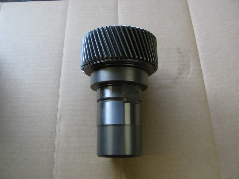 |
Here is the new Atlas-4SP 32-spline input shaft. Part number 340332. |
||||||||||||||||||||||||||||||||||||||||||||||||||||
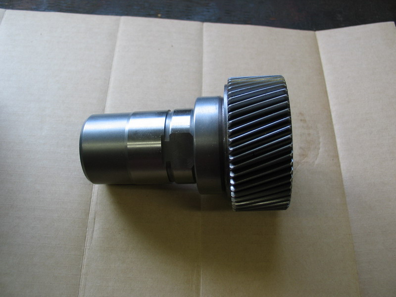 |
Side view of the new 32-spline input shaft. Note the helical cut gears that mesh with the planetary gears in the 4-speed's planetary housing. The internal spline length is 2-1/8", and from the inside bottom of the input shaft to outside end measures 2-5/16". |
||||||||||||||||||||||||||||||||||||||||||||||||||||
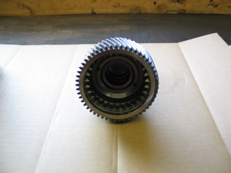 |
View of the new input shaft from the inside-end. | ||||||||||||||||||||||||||||||||||||||||||||||||||||
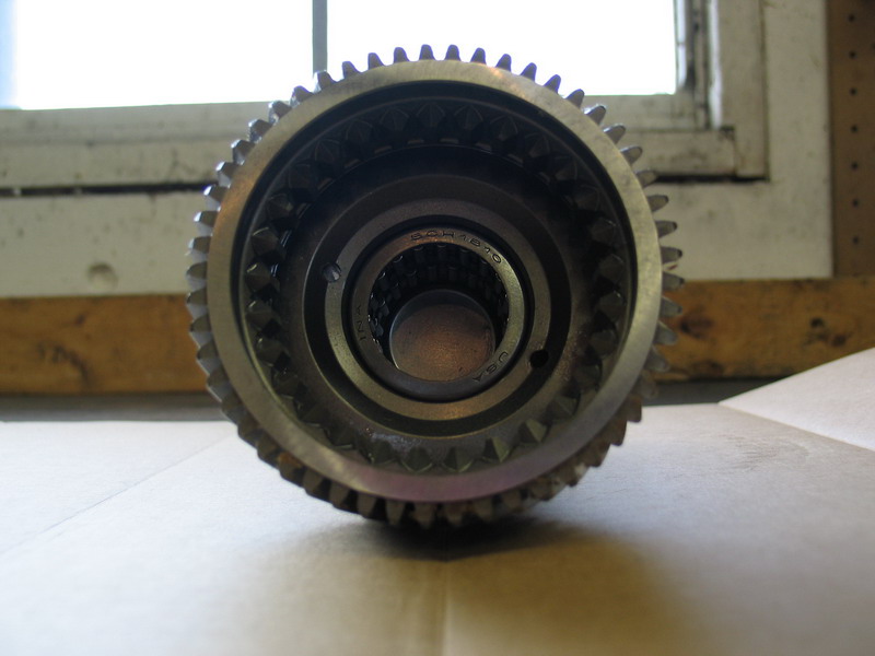 |
The new input shaft ships from Advance Adapters with the two required needle bearings already installed. The bearings are part numbers 340361 (first one) and 340362 (second one). You can clearly see them inside the shaft in this picture. |
||||||||||||||||||||||||||||||||||||||||||||||||||||
 |
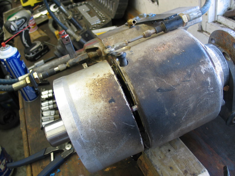
Before we explore the process and our options involved with mating the Atlas-4SP to the back of the TH400, the first job is to swap out the input shaft. Before we tear into the Atlas, first drain the oil. This is the planetary reduction assembly of the four-speed Atlas with my original 23-spline input shaft. |
||||||||||||||||||||||||||||||||||||||||||||||||||||
 |
The first step is to remove the six socket-head cap screws securing the planetary housing to the transfer case. "socket-head cap screw" is the technical term for an Allen-head bolt. The screws require a 5/16" Allen-key or hex-drive socket. |
||||||||||||||||||||||||||||||||||||||||||||||||||||
 |
Once loosened, you will have to work them out with a pair of pliers as they are long and will be coated with sealing compound which causes them to stick in their bores. | ||||||||||||||||||||||||||||||||||||||||||||||||||||
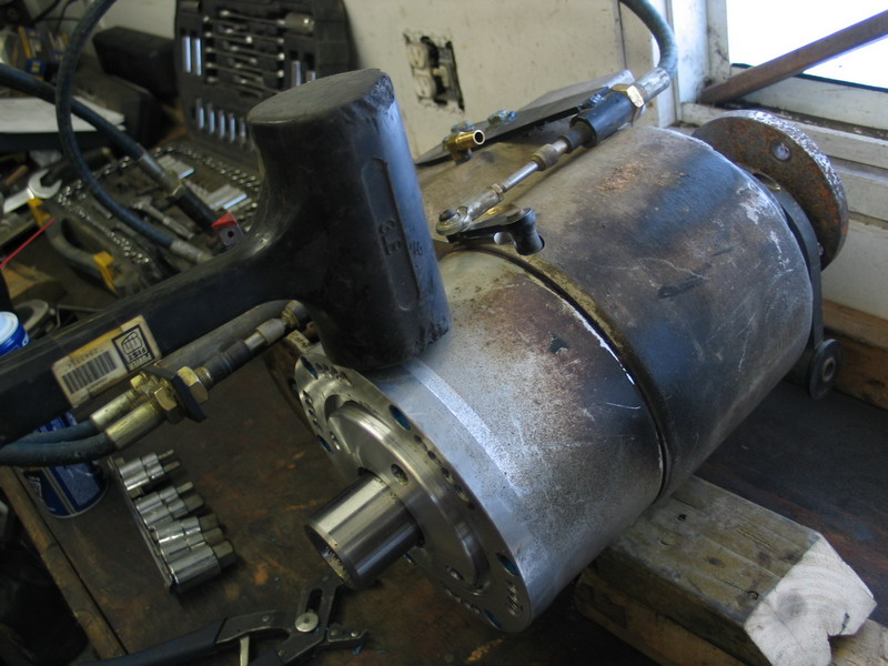 |
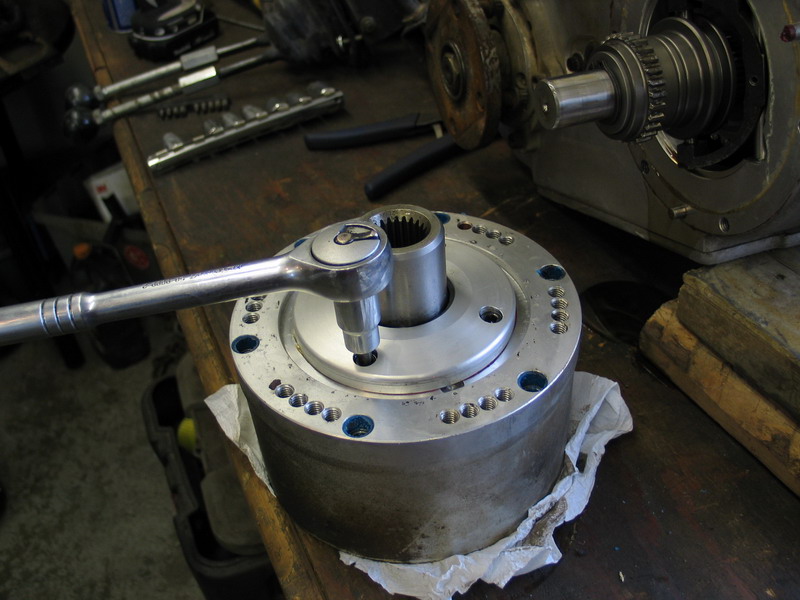
With the six cap screws removed, strike the planetary housing with a plastic or rubber mallet or dead-blow hammer, to separate it from the transfer case. Hold the input shaft as you do so so that the planetary housing doesn't loosen suddenly and fall away uncontrolled, smashing to the concrete floor with a bang (don't ask!) |
||||||||||||||||||||||||||||||||||||||||||||||||||||
 |
You will have to strike the planetary housing several times to loosen it as it is doweled to the main case and is a tight fit. | ||||||||||||||||||||||||||||||||||||||||||||||||||||
 |
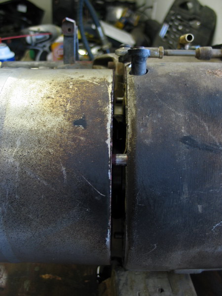
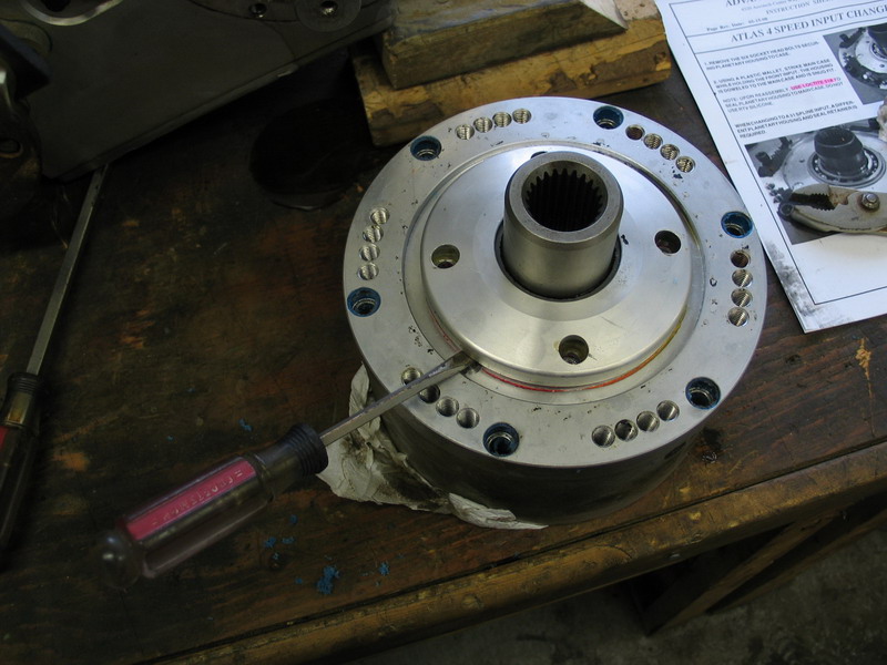
Once you have a gap established between the two, you can use a plastic or wooden tool to gently ease the separation of the two components. DO NOT use a metal tool such as a screwdriver as you will gouge the aluminum (don't ask!) |
||||||||||||||||||||||||||||||||||||||||||||||||||||
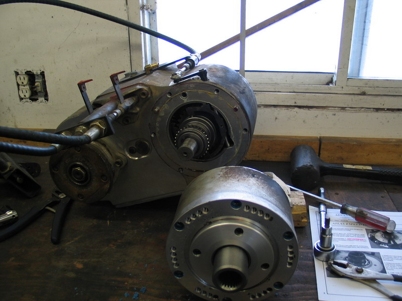 |
With a little effort you will have separated the planetary housing from the main case. | ||||||||||||||||||||||||||||||||||||||||||||||||||||
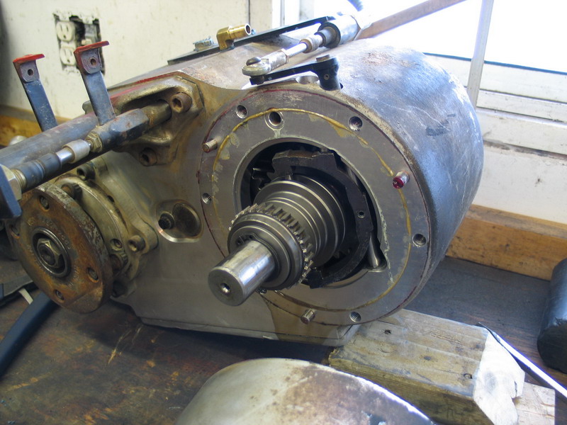 |
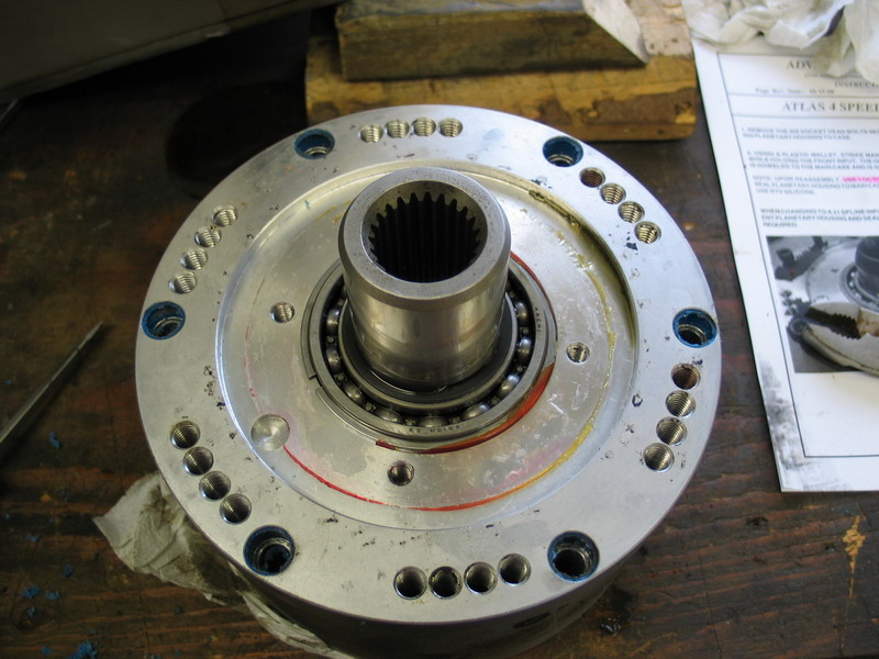
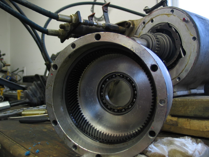
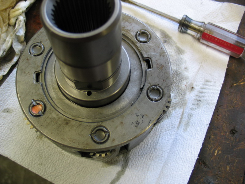
With the planetary housing removed, a view of the main case's input shaft. | ||||||||||||||||||||||||||||||||||||||||||||||||||||
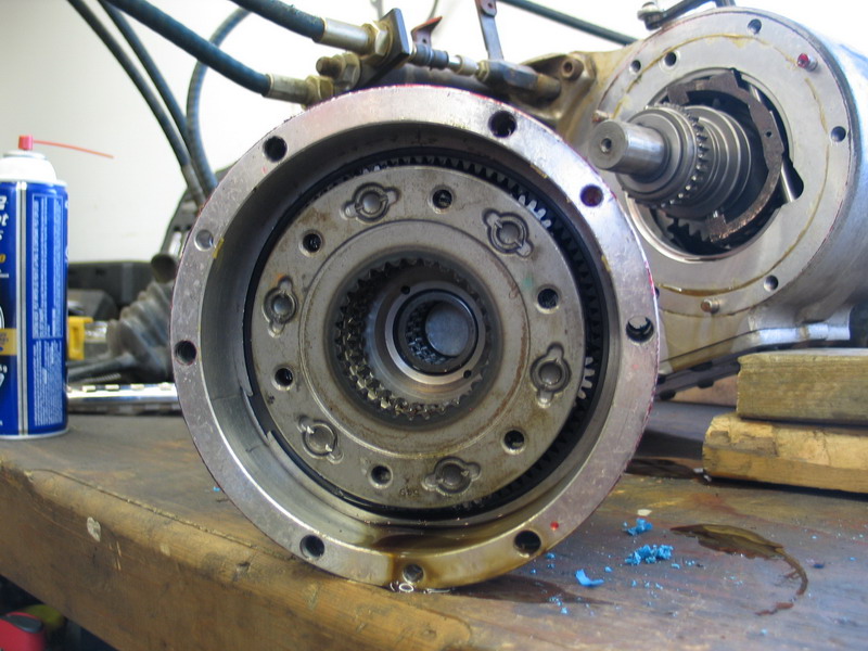 |
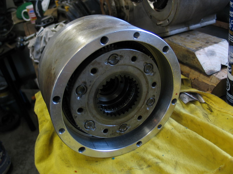
The "inside" side of the planetary housing, showing the 6-gear planetary gear set. | ||||||||||||||||||||||||||||||||||||||||||||||||||||
 |
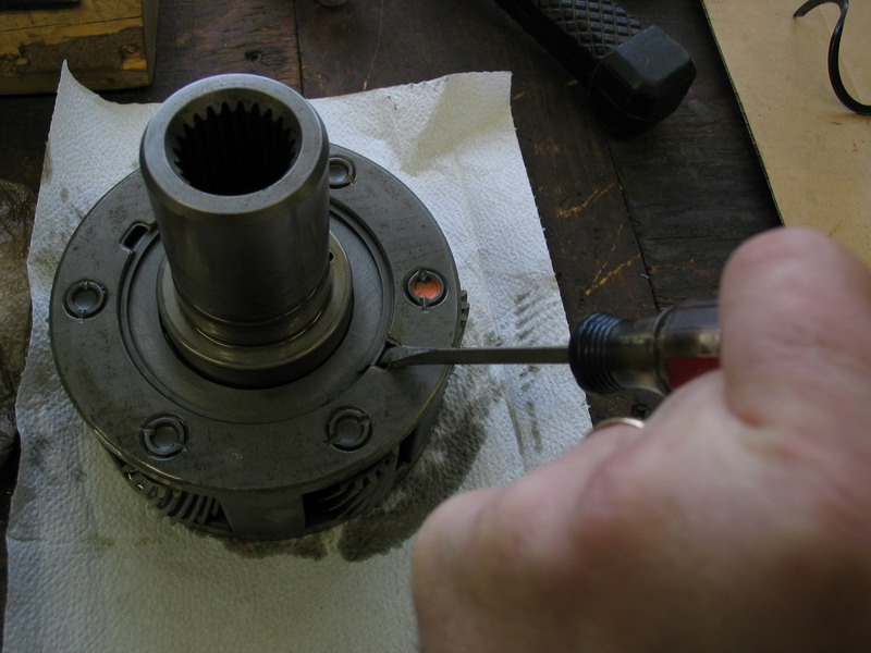
The next step is to remove the four socket head cap screws that secure the input seal retainer to the planetary housing. |
||||||||||||||||||||||||||||||||||||||||||||||||||||
 |
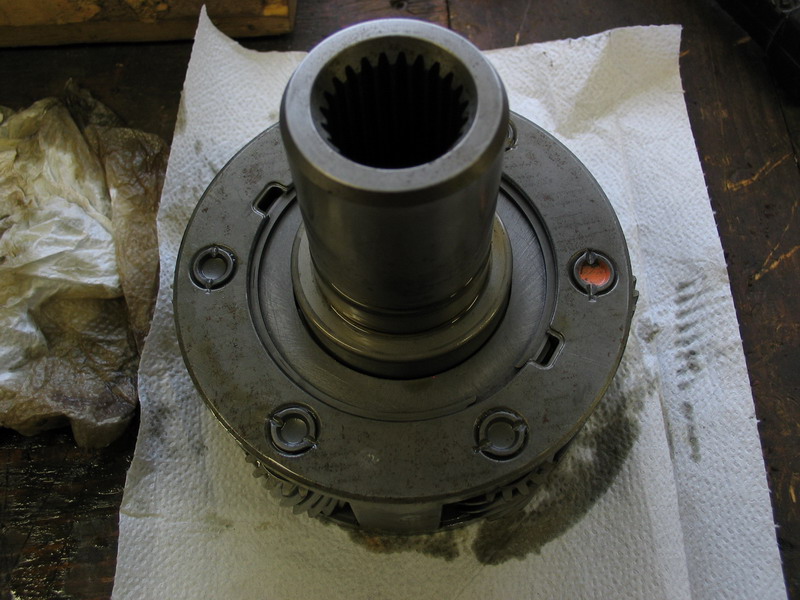
Screws removed from the input seal retainer. Note the small relief in the face of the planetary housing just at the edge of the seal retainer, at about the 7 'o' clock position in this picture. |
||||||||||||||||||||||||||||||||||||||||||||||||||||
 |
Insert a small screwdriver or other prying tool and gently pry the input seal retainer from the planetary housing. | ||||||||||||||||||||||||||||||||||||||||||||||||||||
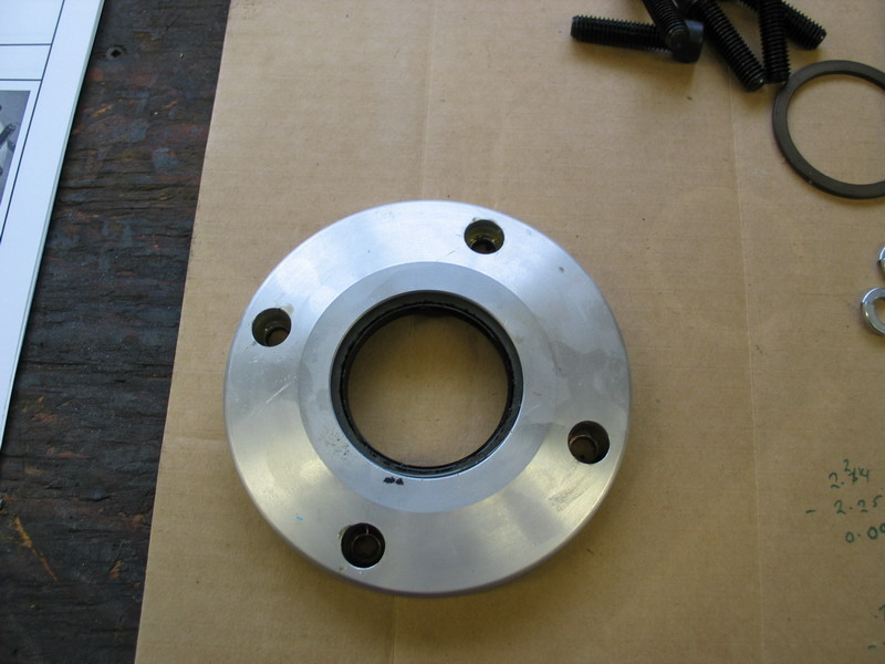 |
Removed input seal retainer. | ||||||||||||||||||||||||||||||||||||||||||||||||||||
 |
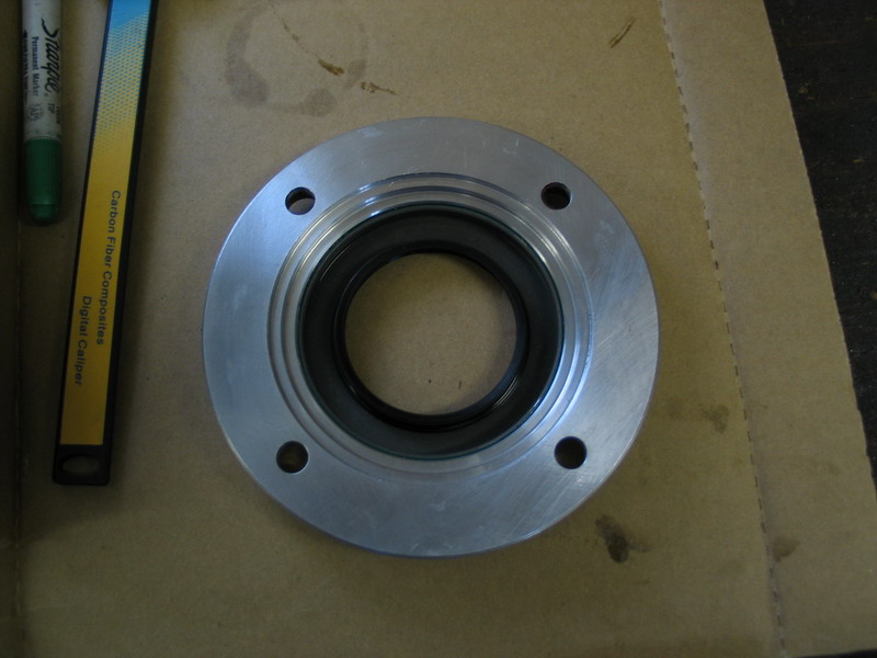
Back side of the input seal retainer, showing the seal. If the seal is in good condition, it need not be removed and can be reused. If the seal is worn, now is a good time to replace it. |
||||||||||||||||||||||||||||||||||||||||||||||||||||
 |
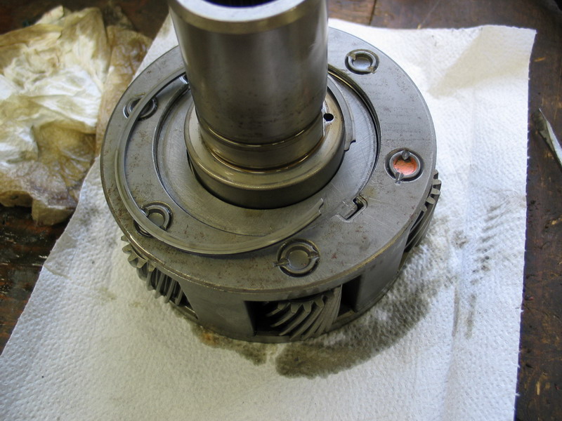
Planetary housing with input seal retainer removed. | ||||||||||||||||||||||||||||||||||||||||||||||||||||
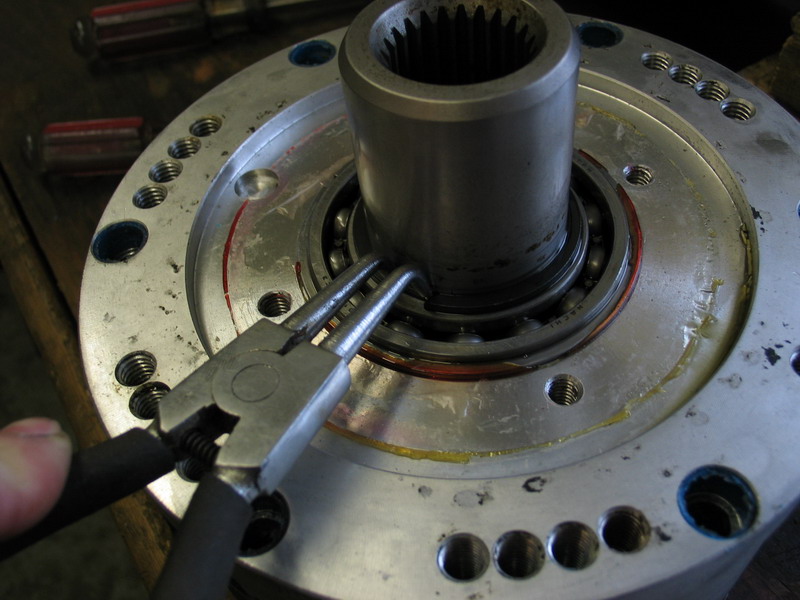 |
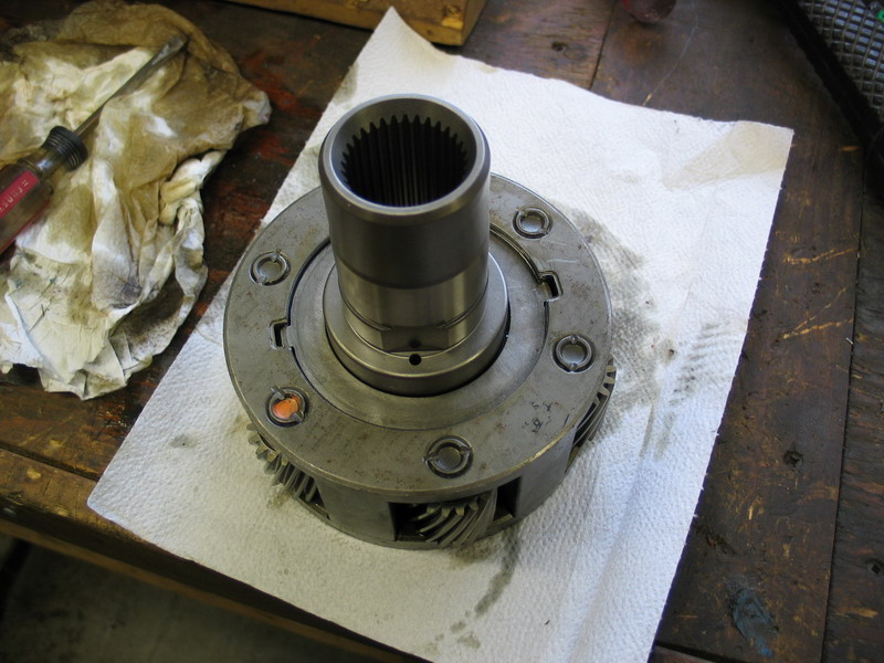
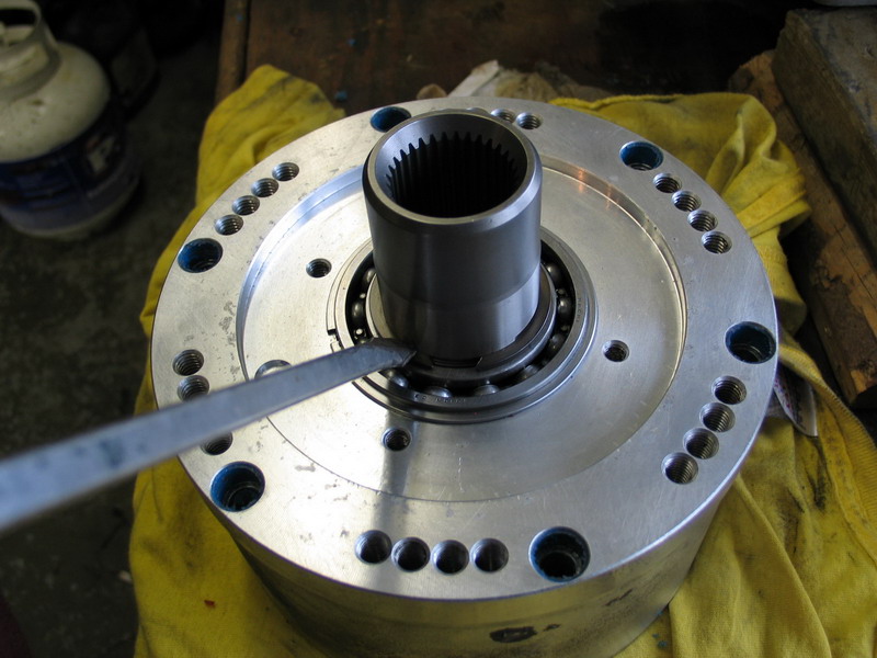
Remove the snap-ring from the input shaft and discard it. This snap-ring secures the input shaft and entire 6-gear planetary gear assembly in the planetary housing. |
||||||||||||||||||||||||||||||||||||||||||||||||||||
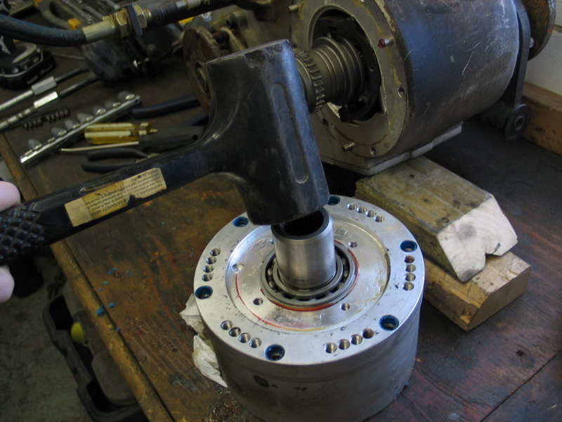 |
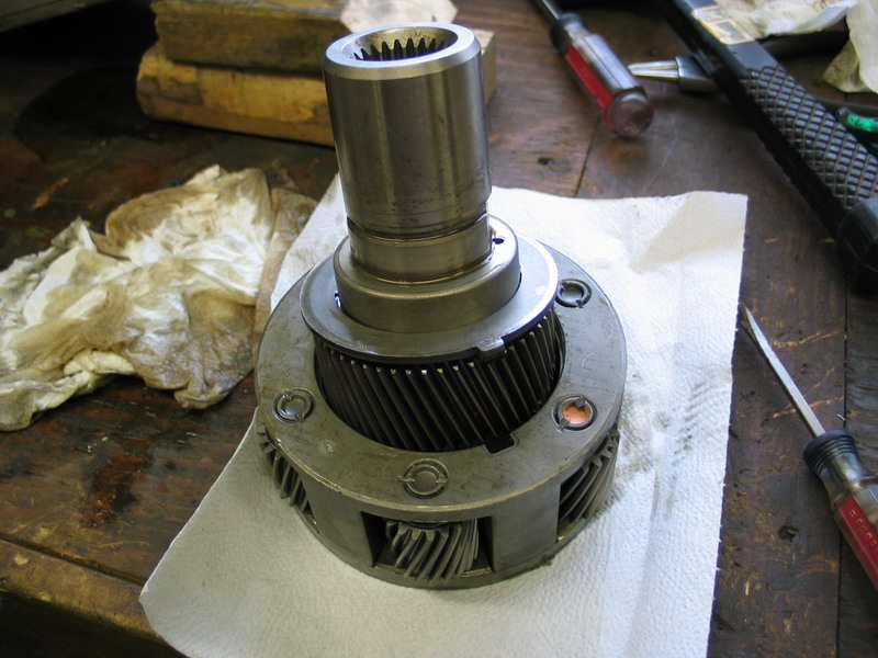
With a soft-faced hammer or mallet, tap the input shaft to remove the input shaft and 6-gear planetary gear set from the planetary housing. | ||||||||||||||||||||||||||||||||||||||||||||||||||||
 |
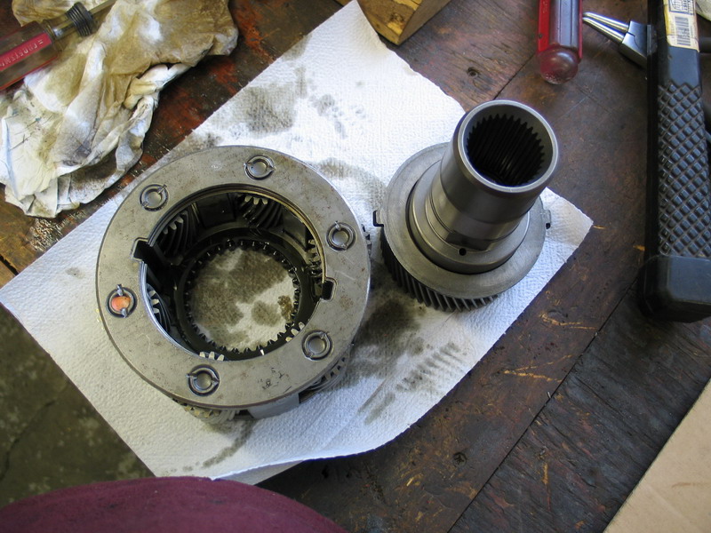
Remove the input shaft and 6-gear planetary gear set from the back-side of the planetary housing. | ||||||||||||||||||||||||||||||||||||||||||||||||||||
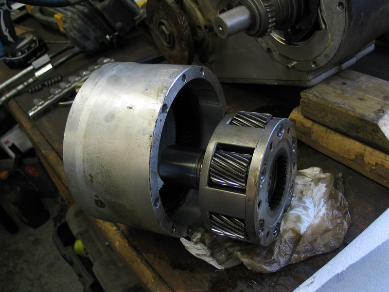 |
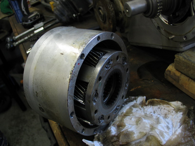
Input shaft and 6-gear planetary gear set removed from the planetary housing. | ||||||||||||||||||||||||||||||||||||||||||||||||||||
 |
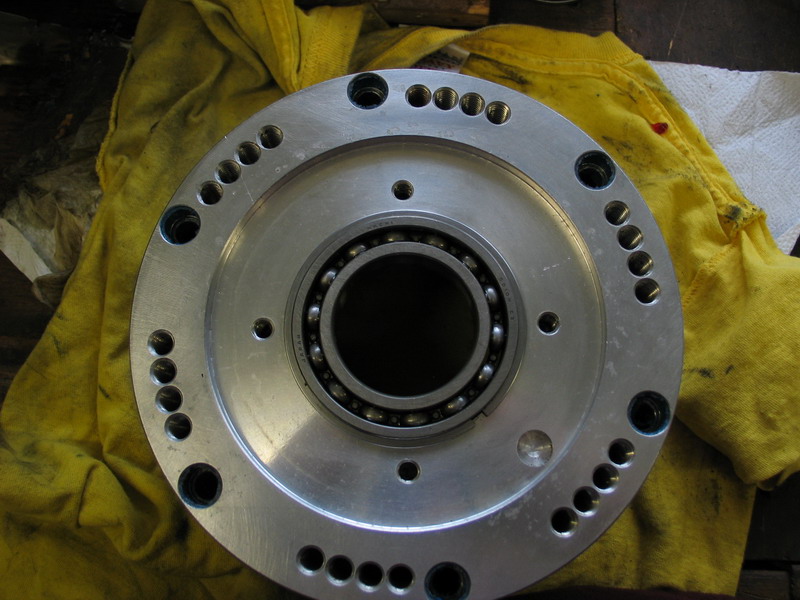
Inside of the planetary housing with the planetary gearset removed. | ||||||||||||||||||||||||||||||||||||||||||||||||||||
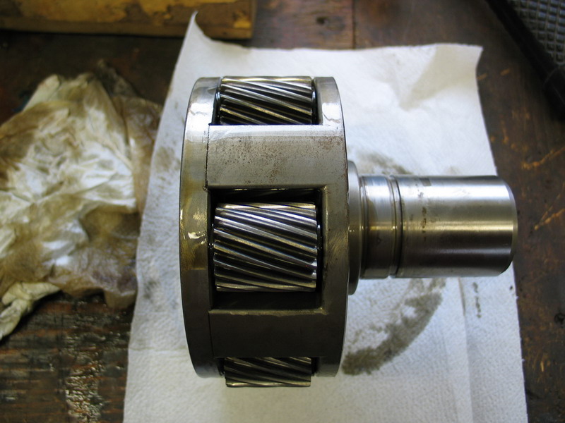 |
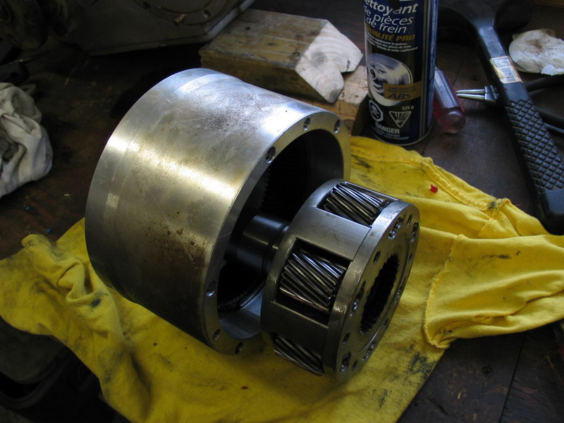
Input shaft and 6-gear planetary gear set. | ||||||||||||||||||||||||||||||||||||||||||||||||||||
 |
The next step is to remove the input shaft from the 6-gear planetary assembly. | ||||||||||||||||||||||||||||||||||||||||||||||||||||
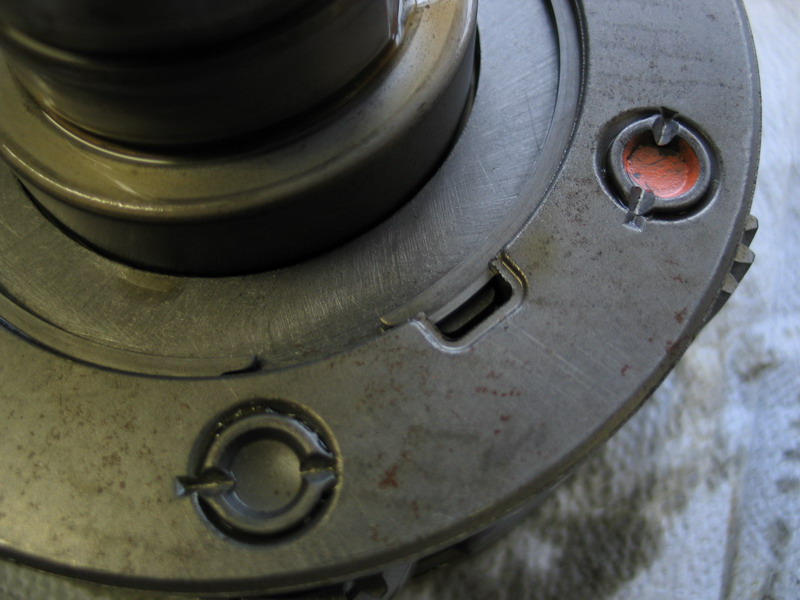 |
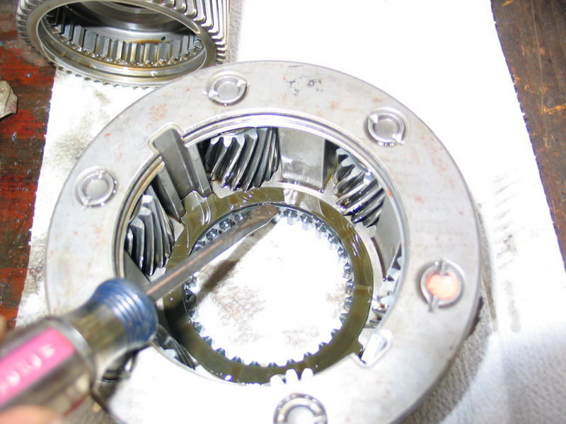
Locate the lock-ring relief in the 6-gear planetary assembly. | ||||||||||||||||||||||||||||||||||||||||||||||||||||
 |
Insert a small flat-bladed screwdriver into the relief... | ||||||||||||||||||||||||||||||||||||||||||||||||||||
 |
... and remove the snap-ring that secures the input shaft in the 6-gear planetary assembly. | ||||||||||||||||||||||||||||||||||||||||||||||||||||
 |
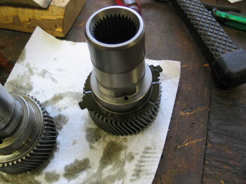
Place the snap-ring to one side for reuse and pull the input shaft from the 6-gear planetary assembly. Note the lock-ring on the input shaft, located just above the helical gear. It looks like a large washer with a tab on it. Underneath this lock ring there is a composite fibre washer. They will both be transferred to the new input shaft prior to it being installed in the 6-gear planetary housing. |
||||||||||||||||||||||||||||||||||||||||||||||||||||
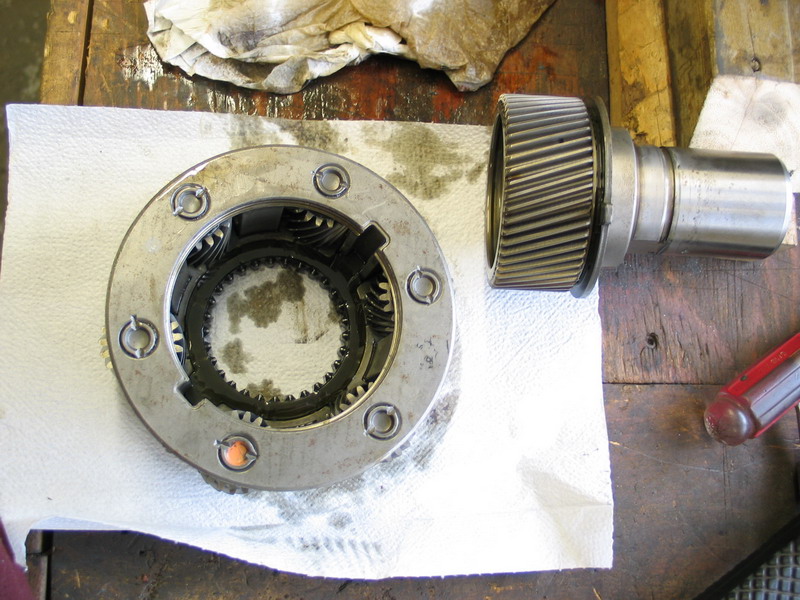 |
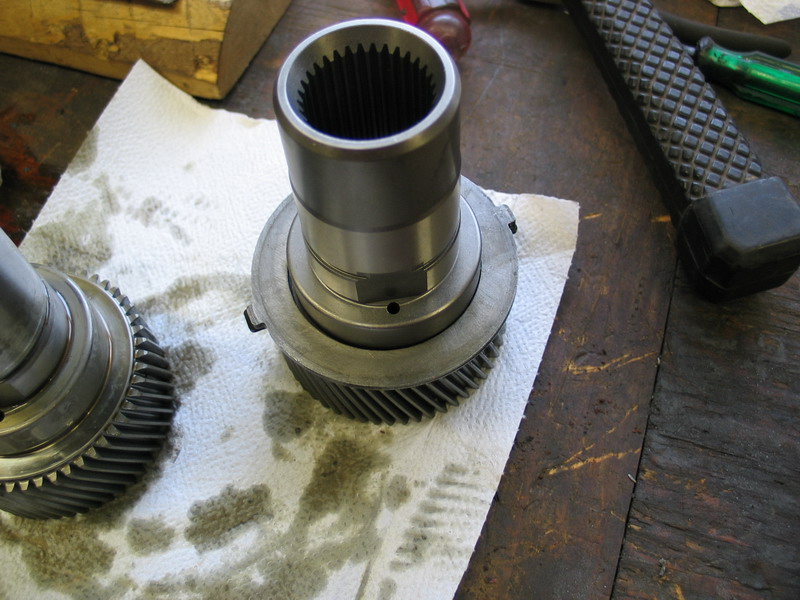
Input shaft and 6-gear planetary assembly separated. | ||||||||||||||||||||||||||||||||||||||||||||||||||||
 |
In the 6-gear planetary assembly there is a second composite fibre washer. Leave this washer in place. | ||||||||||||||||||||||||||||||||||||||||||||||||||||
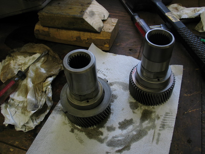 |
Place the new input shaft (on right) next to the removed input shaft (on left). | ||||||||||||||||||||||||||||||||||||||||||||||||||||
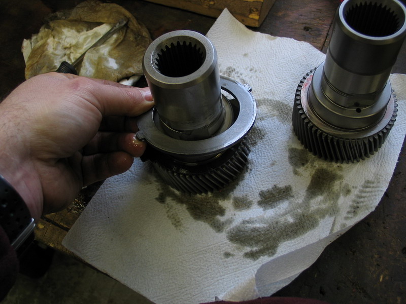 |
From the old shaft, remove the lock ring... | ||||||||||||||||||||||||||||||||||||||||||||||||||||
 |
...and the composite fibre washer. | ||||||||||||||||||||||||||||||||||||||||||||||||||||
 |
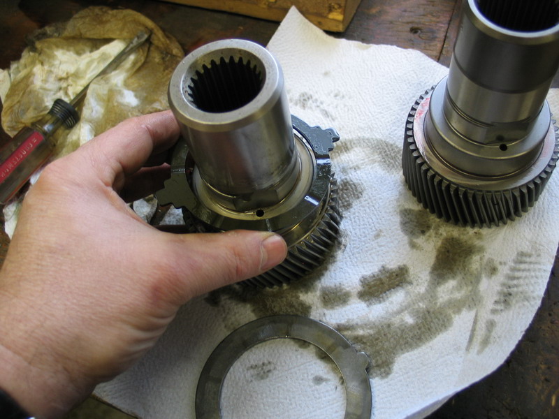
Place the composite fibre washer on the new shaft... | ||||||||||||||||||||||||||||||||||||||||||||||||||||
 |
... followed by the lock ring. | ||||||||||||||||||||||||||||||||||||||||||||||||||||
 |
Double-check the other composite fibre washer is still in place in the correct orientation in the 6-gear planetary assembly... | ||||||||||||||||||||||||||||||||||||||||||||||||||||
 |
... and insert the new input shaft into the planetary assembly. | ||||||||||||||||||||||||||||||||||||||||||||||||||||
 |
Reinstall the snap-ring to secure the input shaft into the 6-gear planetary assembly. | ||||||||||||||||||||||||||||||||||||||||||||||||||||
 |
Thoroughly clean the mating surface of the input seal retainer... | ||||||||||||||||||||||||||||||||||||||||||||||||||||
 |
... and the front of the planetary housing. | ||||||||||||||||||||||||||||||||||||||||||||||||||||
 |
Reinstall the input shaft and 6-gear planetary assembly into the planetary housing. | ||||||||||||||||||||||||||||||||||||||||||||||||||||
 |
Thoroughly clean the back side of the planetary housing. | ||||||||||||||||||||||||||||||||||||||||||||||||||||
 |
Install a new snap-ring over the input shaft using snap-ring pliers to start it... | ||||||||||||||||||||||||||||||||||||||||||||||||||||
 |
... and seat it in the groove on the input shaft with a large, flat-bladed screwdriver. | ||||||||||||||||||||||||||||||||||||||||||||||||||||
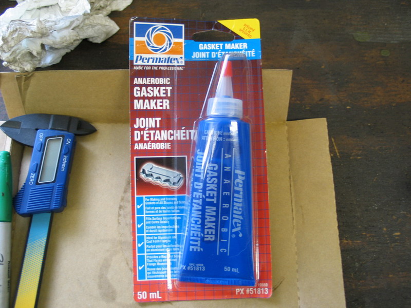 |
It is now time to reassemble the case. For the sealing surfaces, make sure you use Locktite 518 Anaerobic Gasket Maker. Do not use Silicone or other RTV sealants. This is because standard RTV is difficult to get even, consistent, and sufficiently thin when mating precision components. RTV is unsuitable for use between two precision parts where the parallel between the two parts is critical. In addition, RTV begins to cure in air as soon as it is applied, making it time sensitive. In contrast, an anaerobic sealant like Loctite 518 only cures when the two parts are mated and oxygen is excluded from the joint (the word anaerobic means "in the absence of oxygen"). This makes it non-time sensitive, which allows for easy precision alignment without the worry of the sealant beginning to cure prematurely, as can be the case with RTV. |
||||||||||||||||||||||||||||||||||||||||||||||||||||
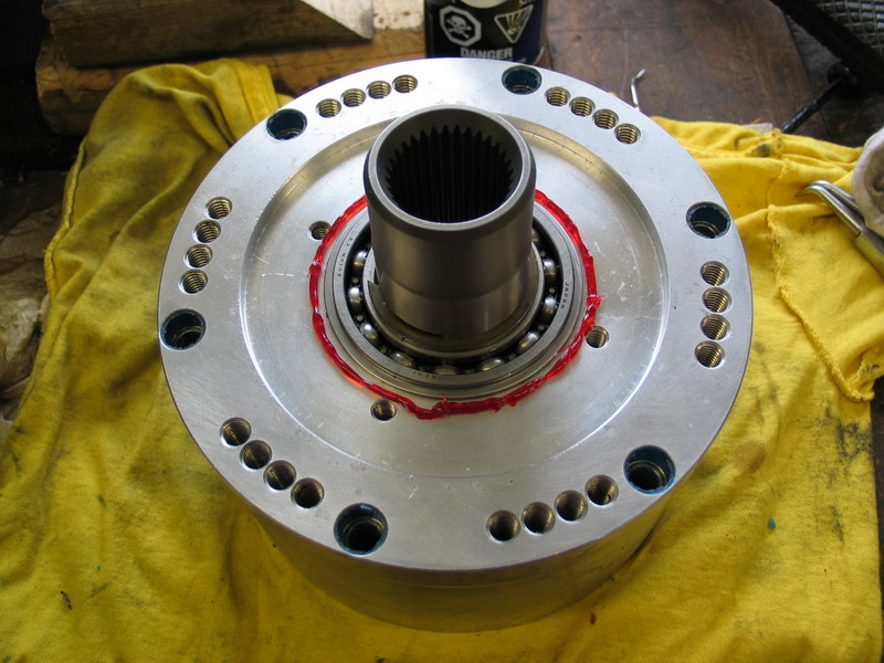 |
Lay a bead of 518 around the input shaft bearing, inside the input seal retainer bolt holes. The other reason for the Loctite 518 is that its viscosity is classified as "thixotropic". This allows it stay put during application but also to flow well when being compressed between the mated components, resulting in a very uniform film thickness. It isn't until this happens that the product begins to cure. Regular RTV sealants simply do not exhibit these properties and can cause problems if used where an anaerobic sealant such as Loctite 518 is called for. |
||||||||||||||||||||||||||||||||||||||||||||||||||||
 |
Install the input seal retainer, insert the 4 socket-head cap screws, and tighten securely. | ||||||||||||||||||||||||||||||||||||||||||||||||||||
 |
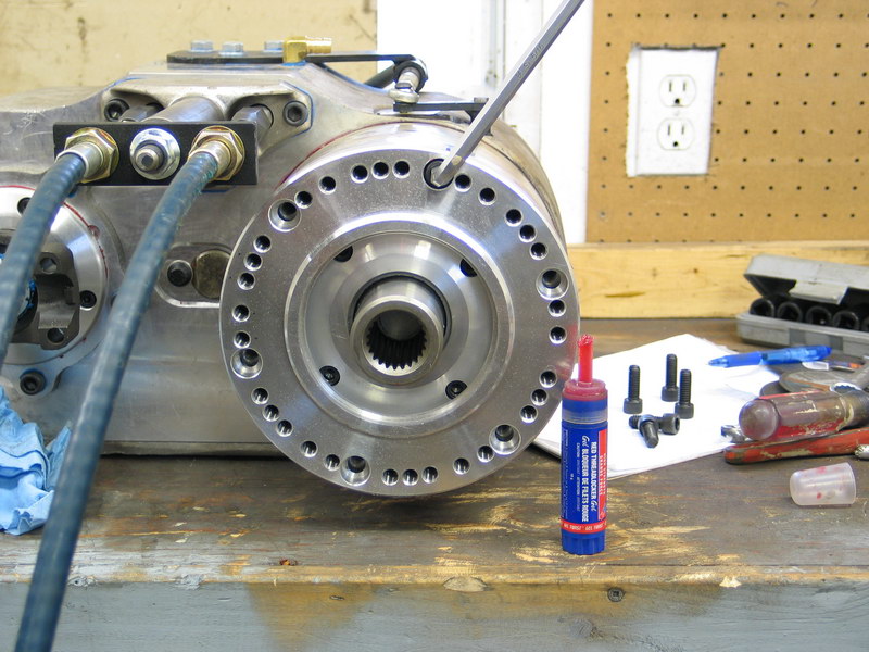
Lay a bead of 518 around the back side of the planetary housing, inside the bolt holes. | ||||||||||||||||||||||||||||||||||||||||||||||||||||
 |
Carefully install the planetary housing onto the main case, making sure the dowel pin and all the bolt holes line up. Prior to reinstalling them, each of the long socket-head cap screws should have a bead of RTV run around their circumference at a point about half the way up the non-threaded area of the shank. This is because these 6 screws thread into holes that go through the front wall of the case and into the oil cavity. Also, each one should have "blue" thread locking compound added to the threads prior to installation. (Loctite 243 is better than 242 for this application, as it has improved oil tolerance). Reinstall the 6 long socket-head cap screws... |
||||||||||||||||||||||||||||||||||||||||||||||||||||
 |
... and tighten them to 30 ft/lbs. in steps in a crisscross pattern. | ||||||||||||||||||||||||||||||||||||||||||||||||||||
 |
Congratulations! You have successfully swapped the Atlas-4SP input shaft. Before installing the Atlas in the vehicle, you must refill it with the proper lubricant and ensure oil is provided to the planetary housing. |
||||||||||||||||||||||||||||||||||||||||||||||||||||
 |
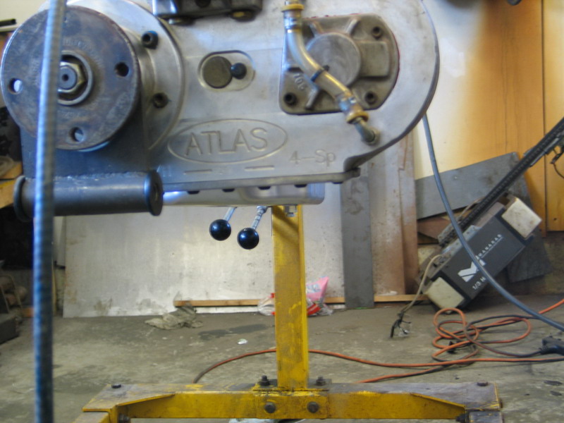
First add 2.5 quarts of the required oil. Stand the case on its front so the rear output shaft points straight up as shown in the pic, and block it in place. Disconnect the upper end of the oil sight tube, and add the oil through the fitting in the case by using a funnel and a short length of rubber hose. |
||||||||||||||||||||||||||||||||||||||||||||||||||||
 |
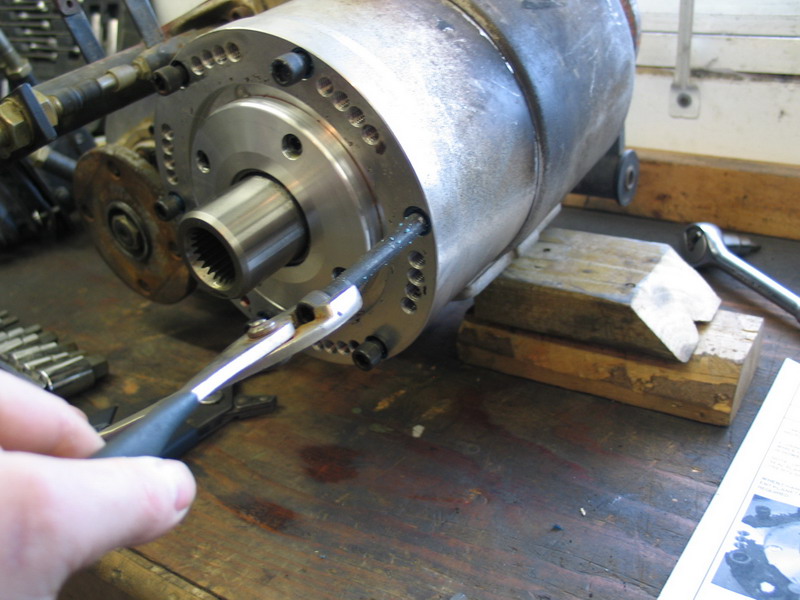
Once the case has been filled, re-attach and tighten the sight-tube hose-end. Be sure to hold the adapter fitting with a wrench while tightening the hose end, as shown. Filling the case while tipped up on its input shaft provides oil to the planetary housing, which is critical before the unit is operated. |
||||||||||||||||||||||||||||||||||||||||||||||||||||
 |
Verify the correct oil level in the sight tube. If you haven't done so already, when the case is installed in the vehicle at the desired rotation (clocking angle) a permanent marker or small zip-tie can be used to mark the "full" level on the sight tube. |
||||||||||||||||||||||||||||||||||||||||||||||||||||
 |
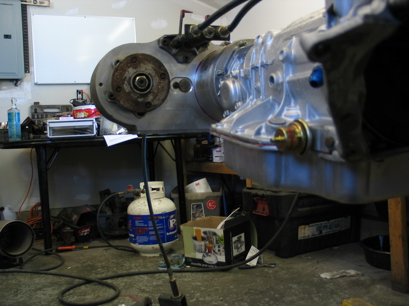
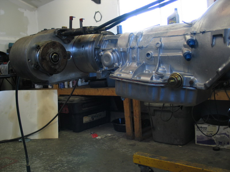
With the case assembled and lubricated, we are ready to move onto the task of mating it to the TH400. | ||||||||||||||||||||||||||||||||||||||||||||||||||||
 |
The TH400 adapter is part number AS-6401. This is the side that mates to the back of the GM TH400 4-speed automatic transmission. |
||||||||||||||||||||||||||||||||||||||||||||||||||||
 |
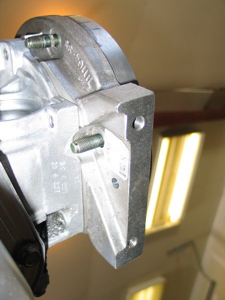
And this is the side to which the Atlas-4SP will bolt. The countersunk holes are the ones used to bolt the adapter to the transmission, using the supplied socket head cap screws. The other bolt pattern is the one to which the Atlas-4SP bolts using the supplied studs and nuts. |
||||||||||||||||||||||||||||||||||||||||||||||||||||
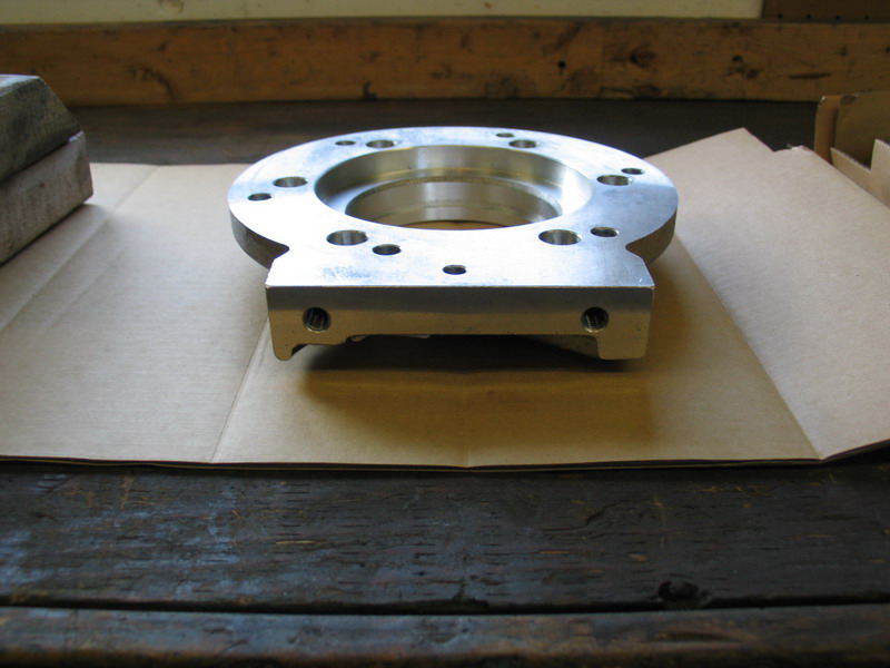 |
The "foot" of the adapter includes two UNC 3/8"-16 threaded holes for cross member mounting. | ||||||||||||||||||||||||||||||||||||||||||||||||||||
 |
Part number AS-0404 is a one-inch thick spacer. You may or may not need this part when mating the Atlas-4SP to a TH400, as I'll explain momentarily. This is the side that mates to the back of the adapter (AS-6401). |
||||||||||||||||||||||||||||||||||||||||||||||||||||
 |
And this is the side to which the Atlas-4SP will bolt if this spacer is used. | ||||||||||||||||||||||||||||||||||||||||||||||||||||
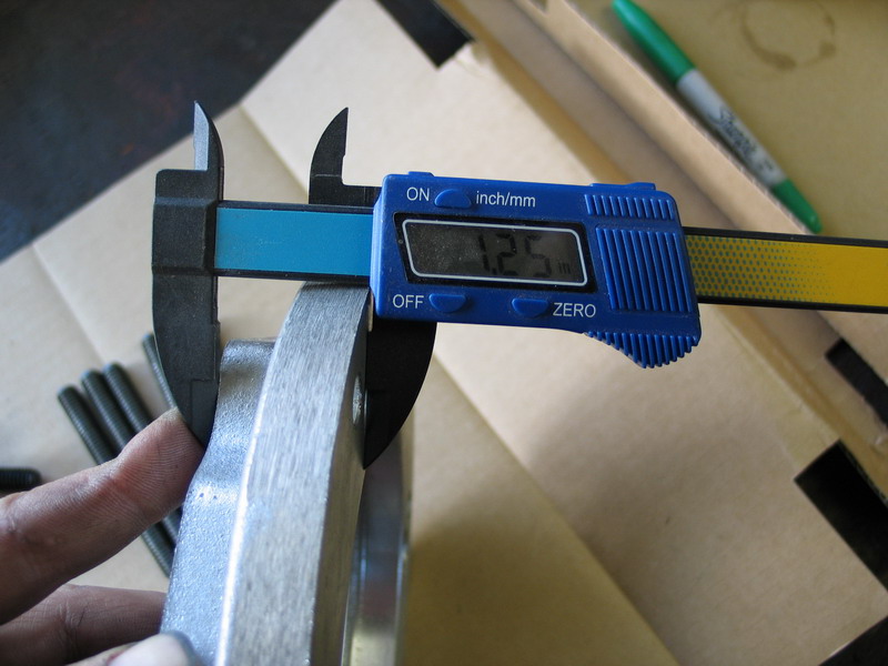 |
The adapter AS-6401 is 1.25" thick. | ||||||||||||||||||||||||||||||||||||||||||||||||||||
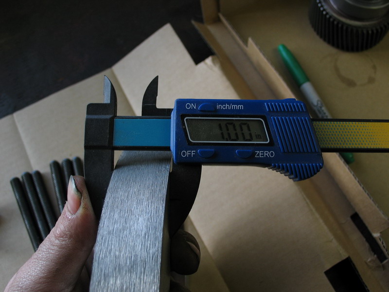 |
The spacer AS-0404 is 1.00" thick. | ||||||||||||||||||||||||||||||||||||||||||||||||||||
 |
For a combined thickness of 2.25". |
||||||||||||||||||||||||||||||||||||||||||||||||||||
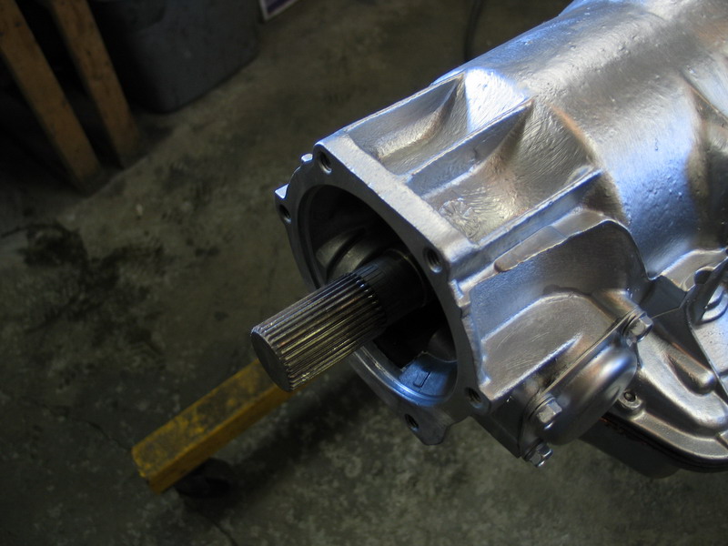 |
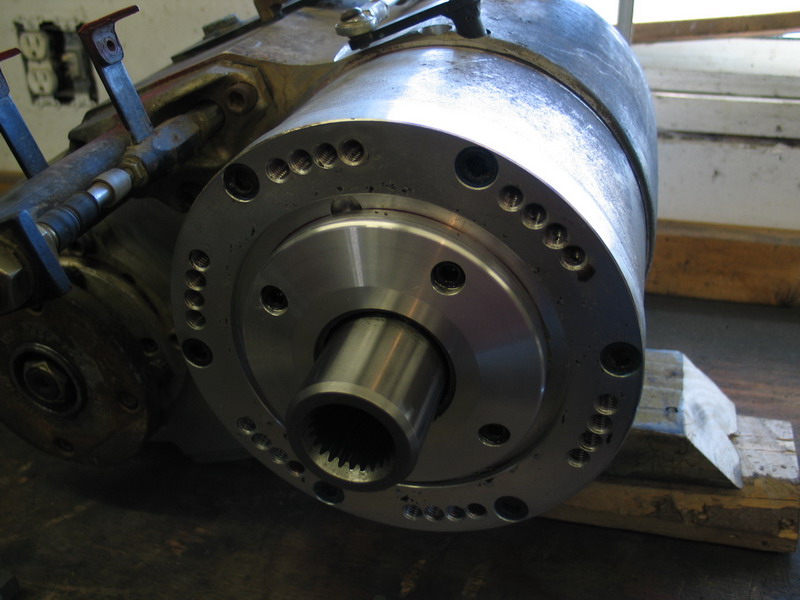
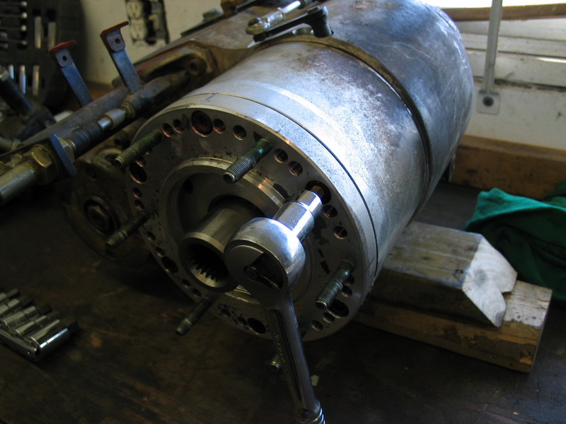
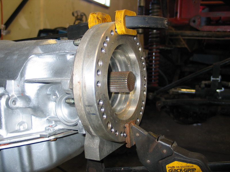
Here's the output of the 4WD TH400, this one out of a one-ton Chevy 4x4 truck. The stock transfer case adapter has been removed. The output shaft has 32 splines, and the spline length is 2-1/4". |
||||||||||||||||||||||||||||||||||||||||||||||||||||
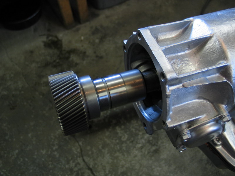 |
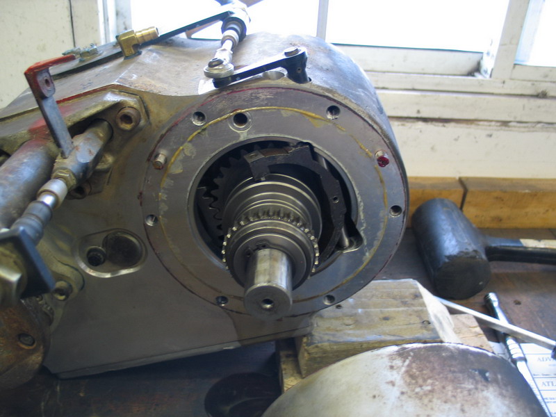
Inside, this is how the Atlas input mates to the TH400 output shaft. |
||||||||||||||||||||||||||||||||||||||||||||||||||||
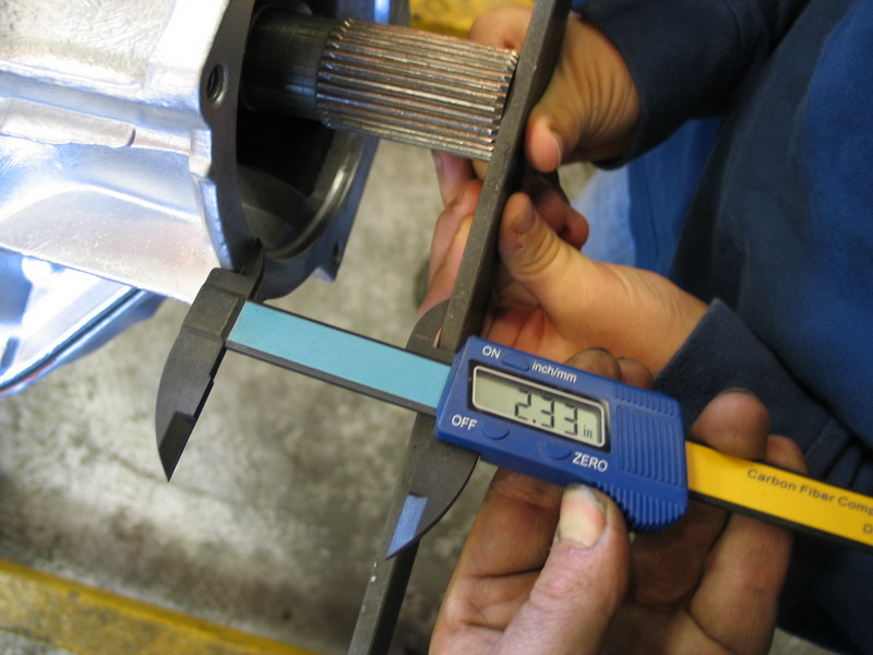 |
Depending on the exact model of 4WD TH400 in question, there are two 32-spline versions suitable for mating an Atlas to, distinguished by the different "stickout lengths" of the output shaft. The shorter, found in TH400s that came from the factory with an NP203 behind them, sticks out about 1.25 inches. The longer one, shown here, sticks out about 2.5 inches. It is found in:
There are two other 4WD TH400's, but niether is ideal for use in front of an Atlas. One is found in 1980 - 1984 TH400s that came from the factory with an NP205 transfer case. It has a stickout length of about 4-1/2". The other is the 10-spline "Jeep" TH400 that has a very long stickout somewhere in the region of 8+ inches. |
||||||||||||||||||||||||||||||||||||||||||||||||||||
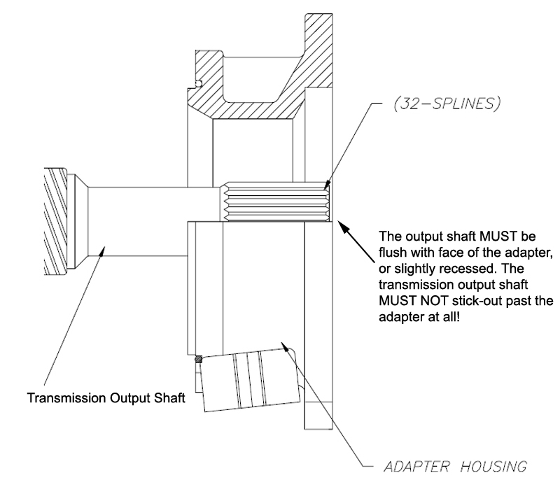 |
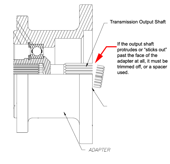
The stickout of the transmission output shaft is very important when mounting an Atlas transfer case. As shown in the diagram at left, there must not be ANY stickout of the shaft beyond the face of the adapter. If there is, even a sixteenth of an inch, and you force the Atlas onto the adapter, you will preload the bearings in the case. If you run the case in this condition, the bearings will be destroyed in very short order - followed by the rest of the internals. A common mistake is to use the mounting nuts to pull the transfer case and adapter together - this is a serious no-no! To summarize - when mounting an Atlas, ANY transmission shaft stickout = very, very bad! |
||||||||||||||||||||||||||||||||||||||||||||||||||||
 |
This is where the 1" thick spacer (AS-0404) comes into play. If you have the longer stickout (~ 2.5"), to mount the Atlas you will need to use the spacer as well as the TH400 adapter. However, even with the adapter and the spacer combined, you will likely still have to trim a little off the output shaft. Let's do the math: My TH400 output shaft has a stickout of 2.33". The adapter (AS-6401) and spacer (AS-0404) combined have a thickness of 2.25", leaving a stickout of 0.08" or about 5/64" (between 1/16" and 1/8"). Granted, with adapter and spacer, there would be the thickness of three gaskets to consider as well, but I wouldn't trust that alone, as the consequences are too severe. Instead, no matter whether you have a TH400 with ~ 1.5" stickout and are using the 1.25" adapter alone; or you have a TH400 with ~ 2.5" stickout and are using the 2.25" adapter/spacer combination, you will have to trim a little off the output shaft. We'll cover how to calculate exactly how much and one other possible solution a little later. |
||||||||||||||||||||||||||||||||||||||||||||||||||||
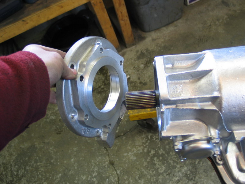 |
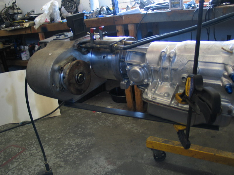
This is how the adapter goes on the back of the transmission. | ||||||||||||||||||||||||||||||||||||||||||||||||||||
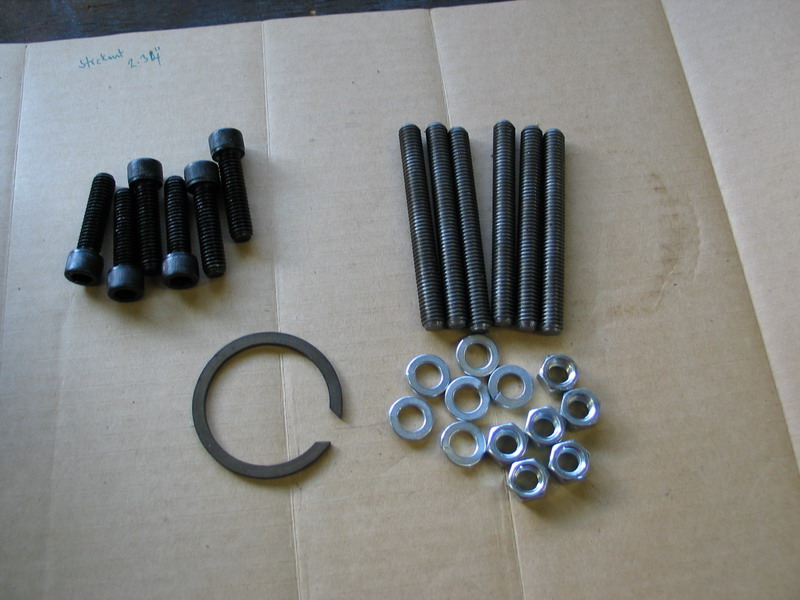 |
This is the hardware kit for the input shaft swap and TH400 mounting. Clockwise from top left we have:
|
||||||||||||||||||||||||||||||||||||||||||||||||||||
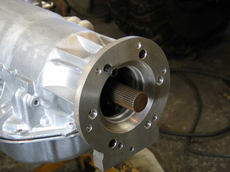 |
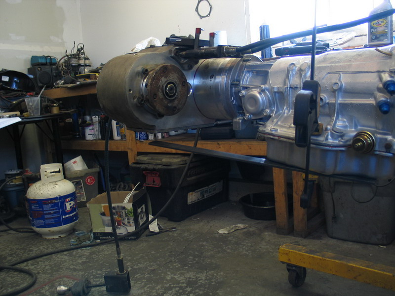
The adapter attaches to the TH400 housing with the six socket-head cap screws inserted through the countersunk holes. | ||||||||||||||||||||||||||||||||||||||||||||||||||||
 |
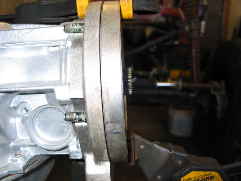
Obviously, with the ~2.5" output shaft and only the 1.25" adapter installed there is significant stickout to deal with. You can't just cut the transmission output shaft off flush with the adapter at this point, as that would leave you with barely any spline engagement. |
||||||||||||||||||||||||||||||||||||||||||||||||||||
 |
Instead, this is where the 1" spacer, AS-0404, is used to "take up" the extra stickout. | ||||||||||||||||||||||||||||||||||||||||||||||||||||
| , | |||||||||||||||||||||||||||||||||||||||||||||||||||||
 |
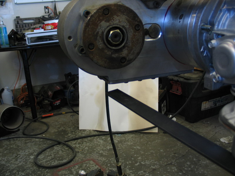
Click on this pic to enlarge it, and you can clearly see the little bit of the shaft that needs to be trimmed off, even with the adapter and spacer used in combination - unless you were willing to gamble on the gasket thickness taking up this extra, which I wouldn't recommend. There are no gaskets in place in this picture, but this is an area where it's definitely better to be safe than sorry. A rotary cutoff wheel can be used to carefully trim the extra length. BUT - there's a catch! |
||||||||||||||||||||||||||||||||||||||||||||||||||||
 |
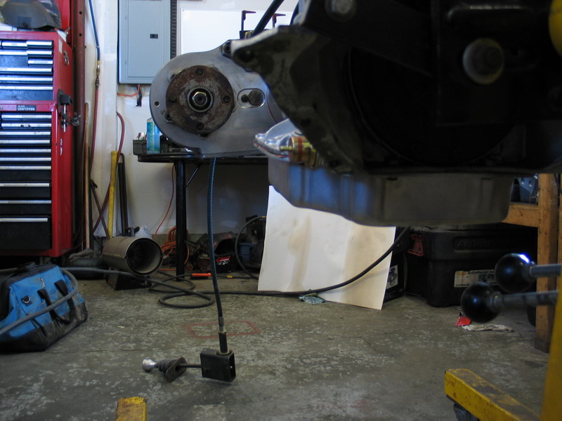
Because of the nonsymmetrical 6-bolt round bolt pattern of the Atlas, when bolting to a TH400 (with or without the spacer), the "flattest" you can clock the case is about 15° (for passenger drop case).
|
||||||||||||||||||||||||||||||||||||||||||||||||||||
 |
That's not too bad, but it does translate to a loss of about 1-1.5" of clearance under the transfer case. In applications where every inch counts, as in a rock buggy, this can be significant. There is a solution, and it even alleviates the requirement to trim the output shaft - but it comes at a cost! |
||||||||||||||||||||||||||||||||||||||||||||||||||||
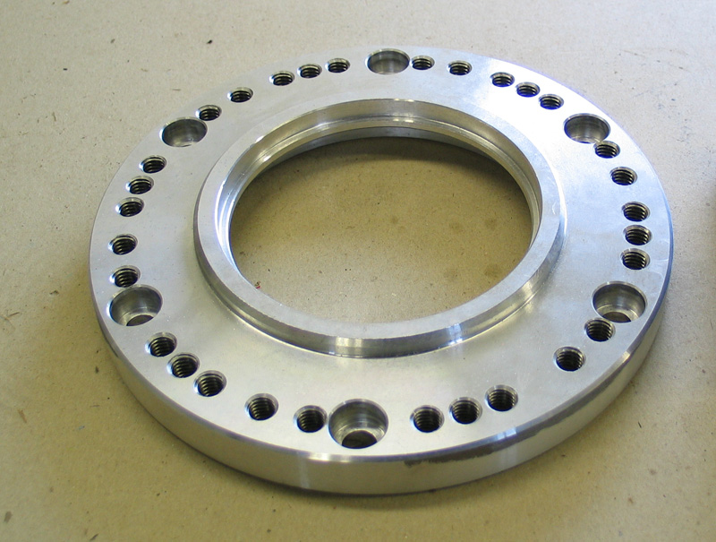 |
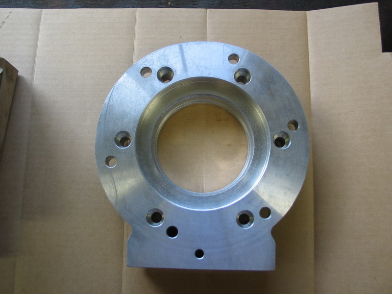
Part no. 51-8603, pictured at left, is a clocking ring that is 3/4" thick and has five (5) different bolt patterns drilled in it. This part can be bolted to the front face of the Atlas before the Atlas is installed and because of the multiple bolt patterns provides a number of different clocking options that wouldn't otherwise be available. |
||||||||||||||||||||||||||||||||||||||||||||||||||||
 |
Here clocking ring 51-8603 is fitted to the back of the previously installed combo of adapter AS-6401 and spacer AS-0404 on the back of the TH400. | ||||||||||||||||||||||||||||||||||||||||||||||||||||
 |
Clearly, if we use 51-8603 we will no longer have any issues with output shaft stickout. We will also have the ability to clock the case at 4°, saving an inch and a half of of ground clearance. But the cost for this is a slight loss of spline engagement (and a 3/4" longer drivetrain!) |
||||||||||||||||||||||||||||||||||||||||||||||||||||
 |
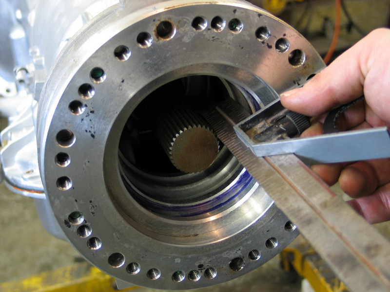
With all 3 pieces on the back of the TH400, total spline engagement between the TH400 output shaft and Atlas-4SP input shaft will be 1-5/8”, limited by the depth the output shaft can reach inside the input shaft splines (because we have spaced the input shaft away from the output shaft), as shown in the pic at left. If we delete part no. 51-8603, we have to trim 1/8" off the shaft to prevent it bottoming in the input shaft. This would leave us with total spline engagement length of 2-1/8". So we have to choose between: 15° clocking, trimming the shaft, 2-1/8" spline engagement |
||||||||||||||||||||||||||||||||||||||||||||||||||||
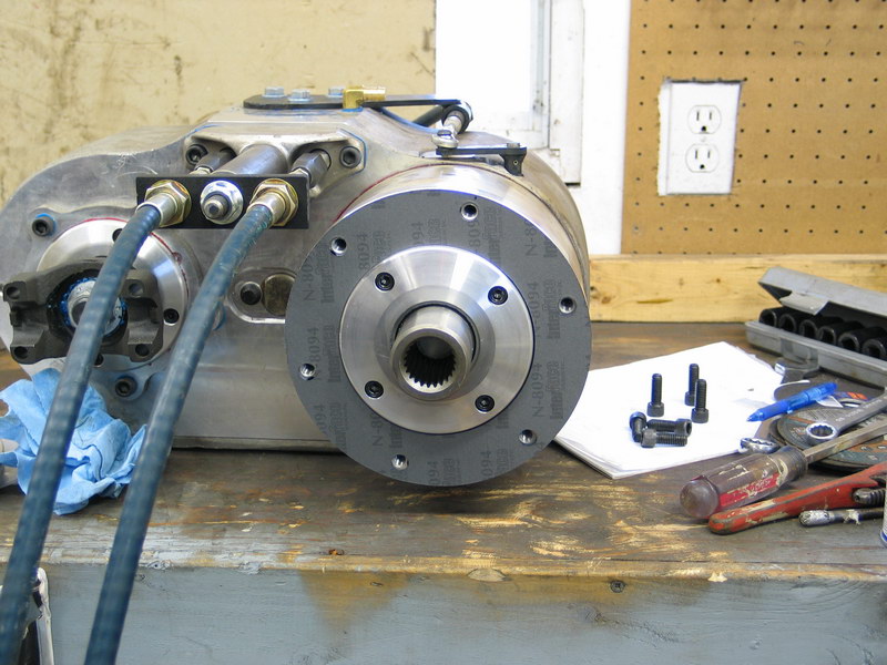 |
If you decide to use clocking ring 51-8603, first install the 6-bolt round gasket that comes with it on the face of the planetary housing. | ||||||||||||||||||||||||||||||||||||||||||||||||||||
 |
Fit the clocking ring in place and install with the six included socket-head cap screws... | ||||||||||||||||||||||||||||||||||||||||||||||||||||
 |
... and torque them to 28-30 ft/lbs. | ||||||||||||||||||||||||||||||||||||||||||||||||||||
 |
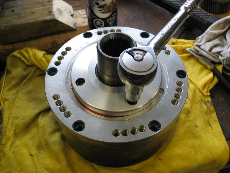
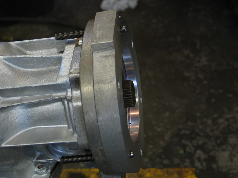
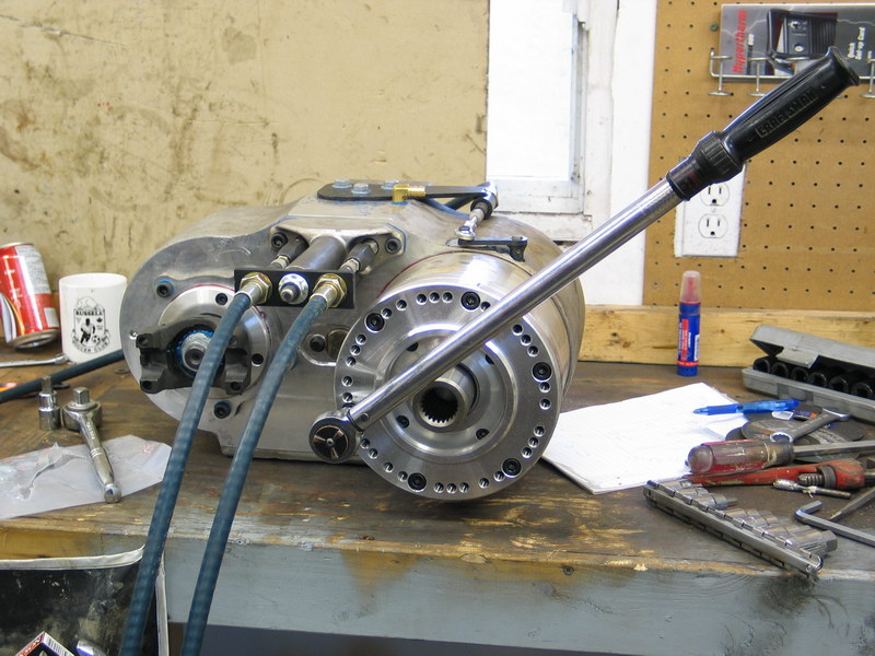
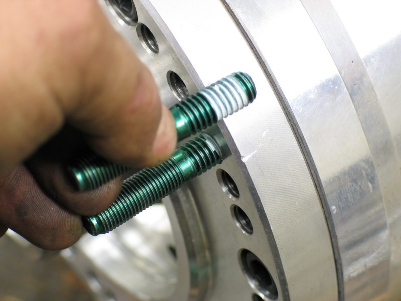
Install the six mounting studs into clocking ring 51-8603 using thread locking compound; in the correct pattern to achieve the clocking angle you desire. Make sure you get each one in the correct position relative to its neighbours (i.e. that there are the same number of holes between each pair). The studs must be installed carefully and tightened securely without over tightening. Getting them properly seated and tightened is a bit of a trick. The procedure I used is as follows: First I threaded on two nuts back-to-back... |
||||||||||||||||||||||||||||||||||||||||||||||||||||
 |
Then with a wrench on the inner nut to keep the outer nut from turning I used a socket on the outer nut to turn the stud into its hole. It's a bit tricky as you have to hold the inner nut fast against the outer nut while rotating the whole assembly together, but you will soon get the hang of it. |
||||||||||||||||||||||||||||||||||||||||||||||||||||
 |
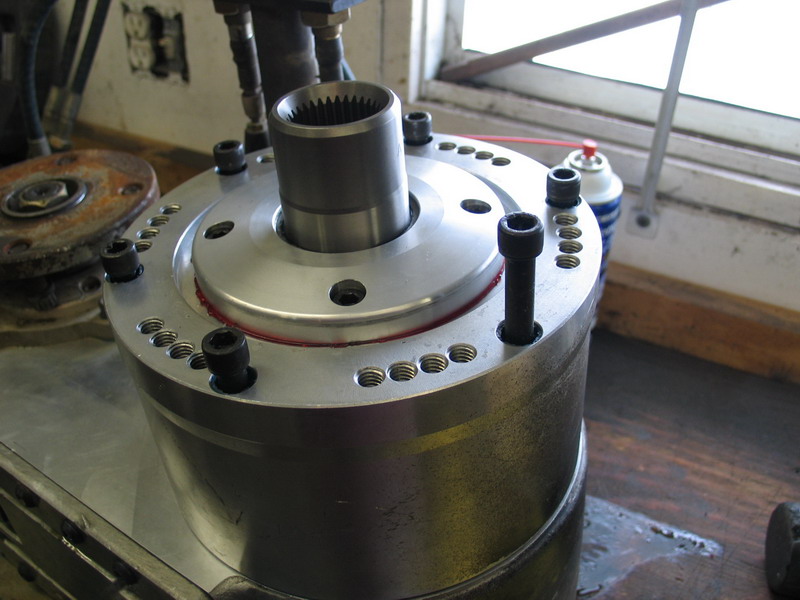
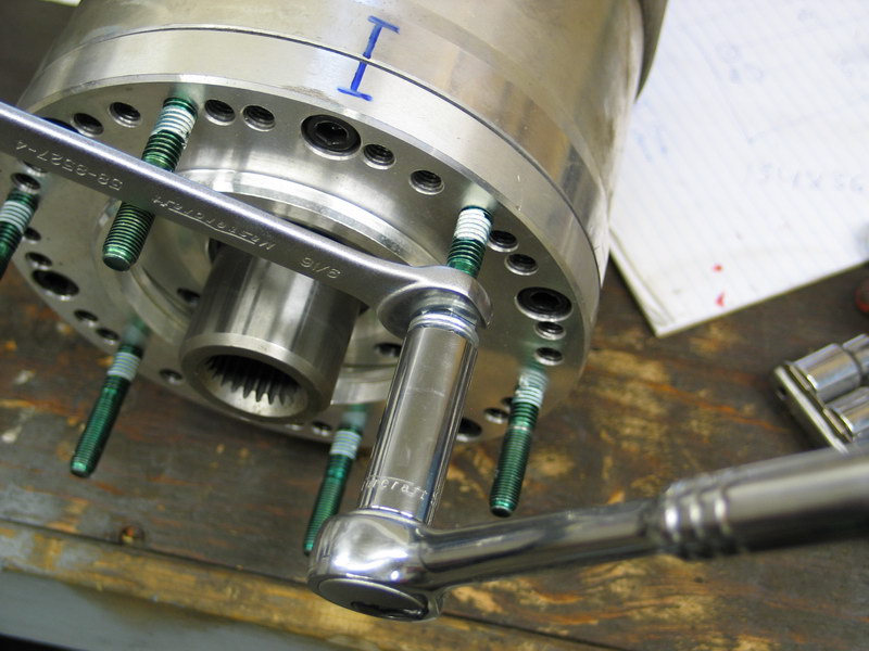
Without a depth or torque spec, and mindful of the need to avoid over-tightening the studs in the aluminum, it is a matter of professional estimation as to how deep to install the studs. | ||||||||||||||||||||||||||||||||||||||||||||||||||||
 |
This pic shows an approximation of how deep I tightened them into the clocking ring. | ||||||||||||||||||||||||||||||||||||||||||||||||||||
 |
Installed clocking ring 51-8603 at 3/4" thick. | ||||||||||||||||||||||||||||||||||||||||||||||||||||
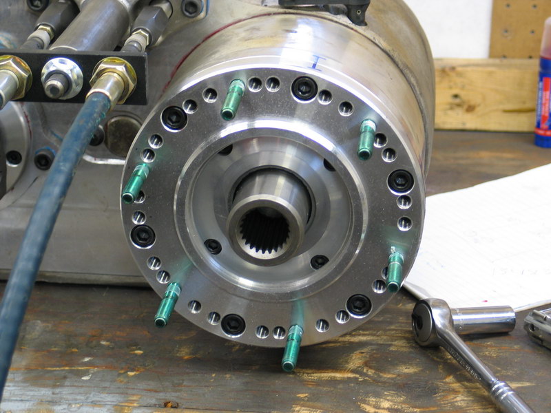 |
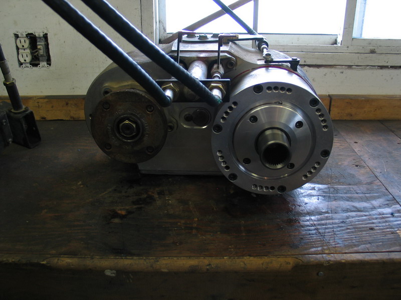
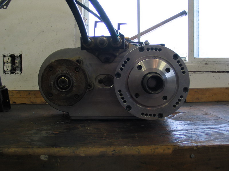
Atlas-4SP with clocking ring 51-8603 installed, ready to be installed on TH400. |
||||||||||||||||||||||||||||||||||||||||||||||||||||
So, at this point I was humming and hawing over whether to trade belly clearance for spline engagement. That is, whether to choose:
or
And I was having a hard time doing it. After all, in a rock rig, an inch or more under the belly is huge. I learned some time ago that a truly flat belly is one of the most important design goals you should have when building a rig, and having the transfer case sit below the transmission pan would either make a flat belly impossible, or force me to lower the whole belly skid and eat up precious clearance under the belly. And belly clearance is a really big deal with today's lower, faster, more stable rigs. On the other hand, I plan to feed approximately 500 ft/lbs of torque through a 2:1 torque converter and then through a 2.75:1 transmission first gear to the tranny output shaft /Atlas input shaft coupling. Not something to be taken lightly, and therefore not somewhere where you want to compromise spline engagement strength. Especially since replacing broken transmission main shafts is neither my idea of fun nor the quickest or easiest of jobs. While worrying my pretty little head over all this, my good friend Andrew "The Sasquatch" Charbolais came up with a brilliant suggestion. Well, it certainly seemed brilliant to me since I hadn't though of it at all. He said, "Why don't you just use the adapter (AS-6401) together with clocking ring 51-8603 for a combined length of 2", get the clocking angle you want, and trim a little more off the shaft but still have more spline engagement than you would have if you used all three adapters/spacers together?" For some reason, I hadn't even thought of this - sometimes the depths of my own denseness astound even me! Anyway, it certainly seemed a good idea, so back out to the shop I went... |
|||||||||||||||||||||||||||||||||||||||||||||||||||||
 |
The first thing I did was remove clocking ring 51-8603 from the Atlas' planetary housing. |
||||||||||||||||||||||||||||||||||||||||||||||||||||
|
And then removed spacer (AS-0404) from the back of the transmission... | ||||||||||||||||||||||||||||||||||||||||||||||||||||
|
... to leave me with just adapter (AS-6401) on the tranny. | ||||||||||||||||||||||||||||||||||||||||||||||||||||
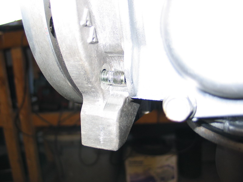 |
I then test-fit clocking ring 51-8603 mounted directly to adapter (AS-6401),and found that there were a couple of spots on the transmission casting that would need clearancing to accommodate the studs in clocking ring 51-8603. One was on the lower right... |
||||||||||||||||||||||||||||||||||||||||||||||||||||
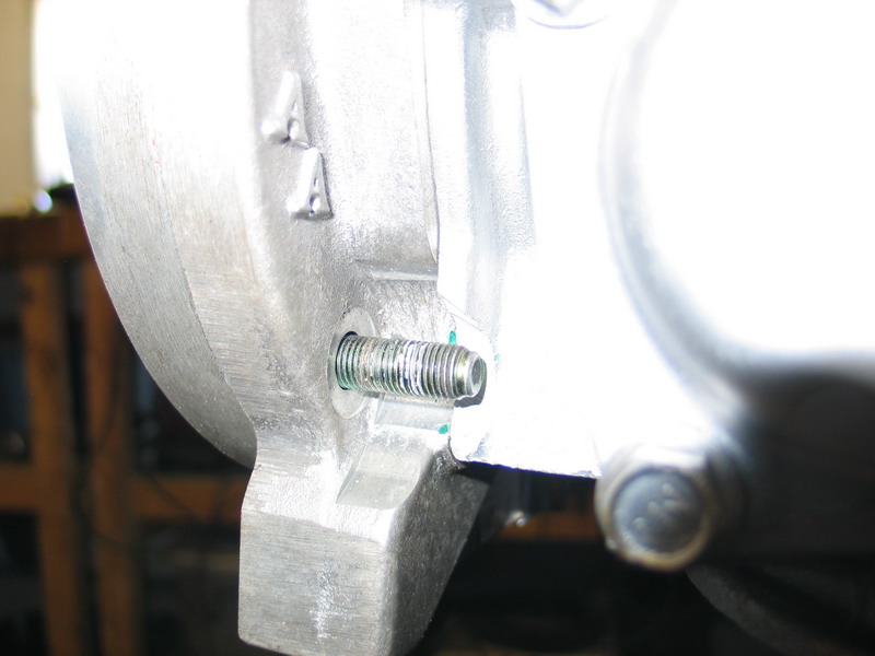 |
... which a little grinding fixed in no time. |
||||||||||||||||||||||||||||||||||||||||||||||||||||
 |
And the other located underneath the transmission. |
||||||||||||||||||||||||||||||||||||||||||||||||||||
 |
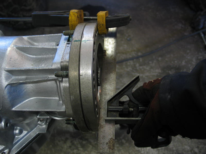
With that taken care of, I clamped the clocking ring directly to the adapter... | ||||||||||||||||||||||||||||||||||||||||||||||||||||
 |
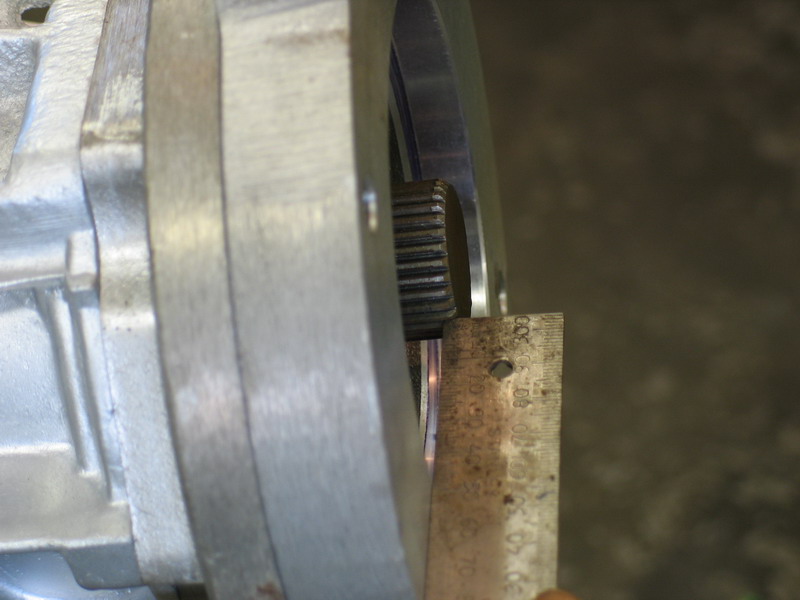
... to measure how much of the shaft I would need to trim. | ||||||||||||||||||||||||||||||||||||||||||||||||||||
 |
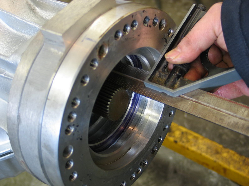
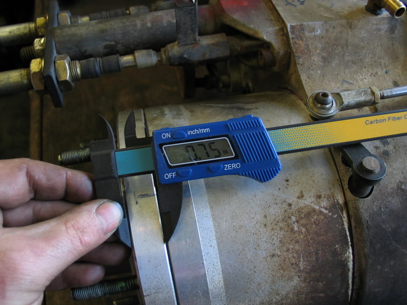
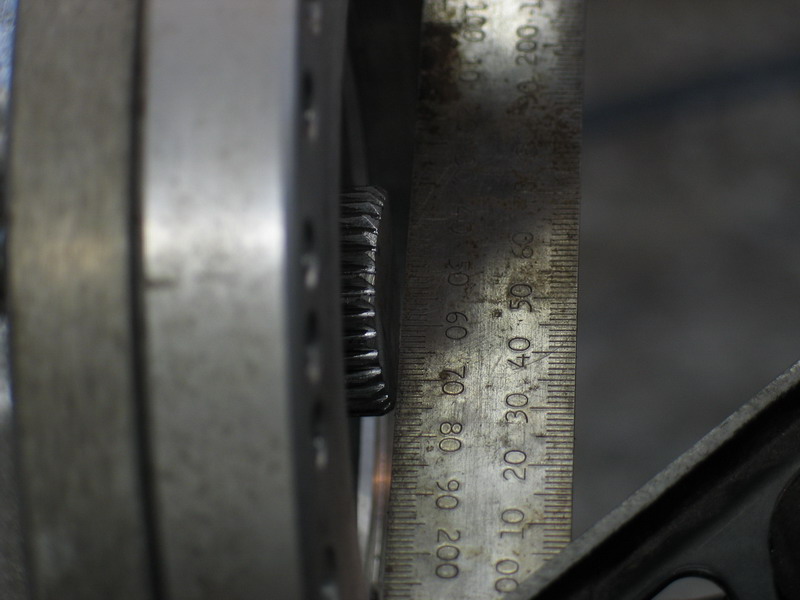
The spline length of the original, unmolested shaft is 2-1/4". I marked the trim line with a green sharpie, and found that, using clocking ring 51-8603 mounted directly to adapter (AS-6401) I would have to trim 7/16" off the shaft, leaving me with 1-13/16" of splines to engage the Atlas-4SP input. (the green line is actually a little deeper on the shaft than necessary here in this pic due to the difficulties in getting the marker inside the transmission to make the mark.) |
||||||||||||||||||||||||||||||||||||||||||||||||||||
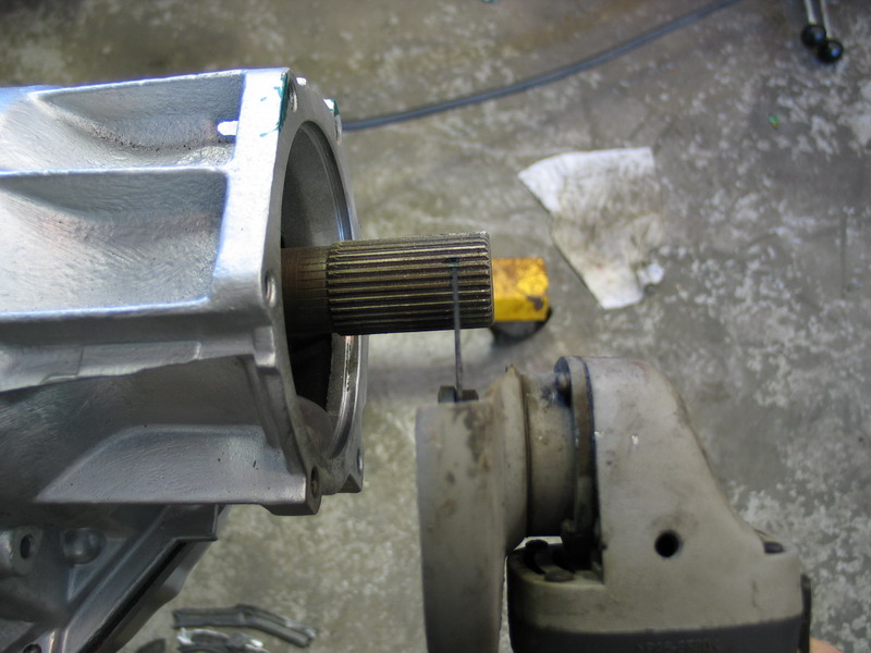 |
Good enough, I though, so out came the cut-off wheel! |
||||||||||||||||||||||||||||||||||||||||||||||||||||
 |
No turning back now! | ||||||||||||||||||||||||||||||||||||||||||||||||||||
 |
Okay, so nobody would accuse me of being the human lathe, and I trimmed perhaps a sixteenth of an inch more than I had to, but as I said earlier, better safe than sorry; and it's actually not critical to have a perfect cut. That said, it would help you enormously in making a clean cut if you were able to turn the shaft while cutting by driving some sort of belt on the input end of the transmission. |
||||||||||||||||||||||||||||||||||||||||||||||||||||
 |
After making the cut, chamfer the end a bit and then dress the splines with a small triangular hand file to ensure the transfer case input will engage the splines smoothly and easily (especially important when you are lying under the rig by yourself bench-pressing the transfer case into place - ask me how I know this!) |
||||||||||||||||||||||||||||||||||||||||||||||||||||
 |
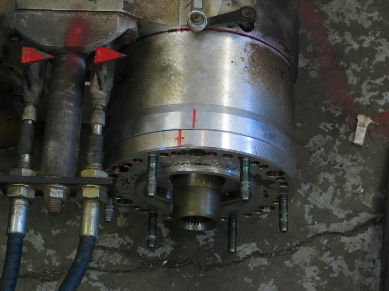
With the shaft cut and no turning back, it's time to explore the clocking options that come with using clocking ring 51-8603. I started by making an indexing mark on the adapter and the clocking ring, inline with the centreline of the transmission. These marks therefore indicate the top centre of the components. |
||||||||||||||||||||||||||||||||||||||||||||||||||||
 |
I then marked a similar line at the top centre position on the Atlas' planetary housing for reference. Now, when test-fitting the clocking ring 51-8603 in different position on the Atlas, I know that if all the red lines line up, the case would be perfectly flat (clocked at 0°). And from there, I can quickly get an idea of the other positions (clocking angles) possible. |
||||||||||||||||||||||||||||||||||||||||||||||||||||
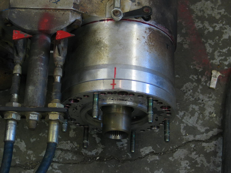 |
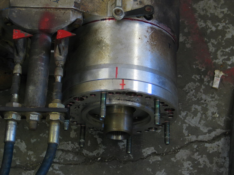
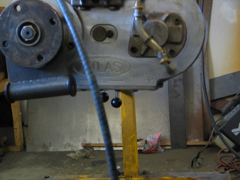
These indexing marks can now be used to give an indication of the different clocking angles possible with the different positions in which clocking ring 51-8603 can be bolted to the Atlas. This is the "flattest" position possible. Since the line on the clocking ring is actually slightly to the left of the line on the case you can tell that this clocking ring position would result in the transfer case actually being clocked "up" slightly (about 1° as it turns out). |
||||||||||||||||||||||||||||||||||||||||||||||||||||
 |
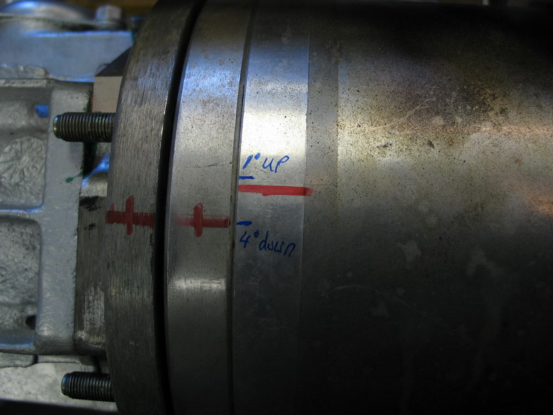
The next flattest position is shown here. The clocking ring line being to the right of the line on the case indicates that this is the more tradition arrangement where the transfer case would be clocked down (the front output lower than the input) - in this instance about 4°. |
||||||||||||||||||||||||||||||||||||||||||||||||||||
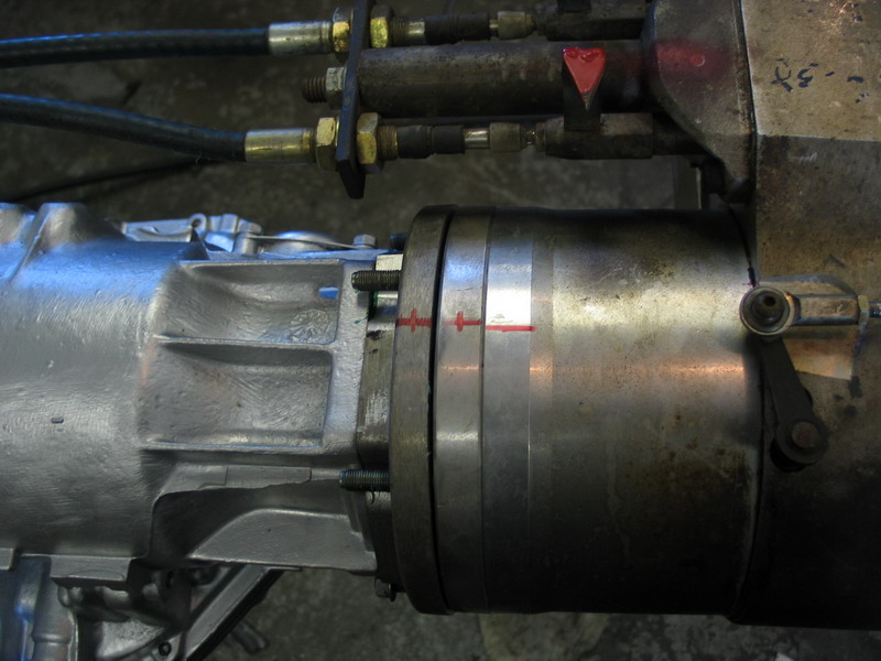 |
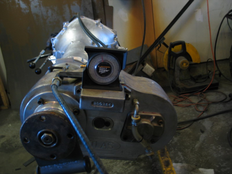
This is the Atlas installed in the 1° up clocking position. | ||||||||||||||||||||||||||||||||||||||||||||||||||||
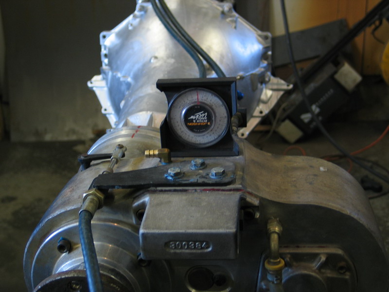 |
Admittedly, my old weld-spattered angle finder has teeny-tiny markings and I have tired old eyes, so you should probably read all of my angle measurements to plus or minus 1°. In essence, this is the transfer case clocked flat. |
||||||||||||||||||||||||||||||||||||||||||||||||||||
 |
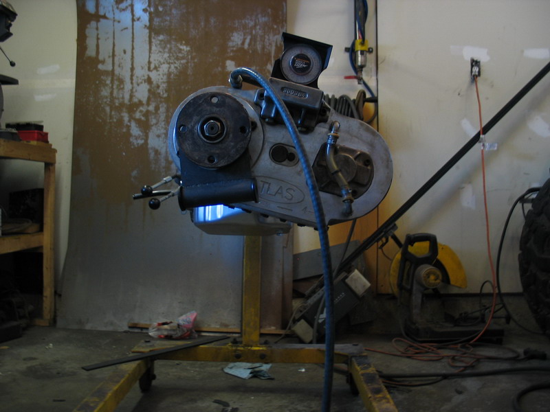
This is the Atlas installed in the 4° down clocking position. |
||||||||||||||||||||||||||||||||||||||||||||||||||||
 |
This is the Atlas installed in the 4° down clocking position. |
||||||||||||||||||||||||||||||||||||||||||||||||||||
As an aside , and at the risk of compicating things and confusing you, there is just one more possibility I should mention. In my case, obviously, I am working with an existing Atlas and fitting it to a different transmission than I had originally. However, if you are considering buying a new Atlas there is another option. If you are sure you want as flat a rotation as possible and you are prepared to deal with any possible interference with the tunnel, floor, frame, seats, etc., you can order the Atlas with a "flat clocking" option. In this case, the actual Atlas case itself is drilled differently. Even with this option, however, it is not always possible to achieve a true 0° clocking, and in fact in some instances it can cause negative rotations (clocking the case "up", above parallel to the ground). Therefore the "flat clocking" option can actually take away from other viable and preferable clocking options. This can be a nasty surprise for people who think they can clock it flat, only to find out during installation that the "flat" rotation can cause interference with the tunnel, frame, pans, etc. In short - if you are considering a "flat clocking" Atlas, be sure to call and discuss your options and setup with AA before ordering. With that said, if a "flat clocking" Atlas will work for you in your rig, it means you could eliminate the need for clocking ring 51-8603, get the case clocked flat or nearly flat and potentially get greater spline engagement than if you had to use clocking ring 51-8603 to get your desired rotation. Now, back to this specific project - What we really need are some good comparison pics in order to get a good idea of the results of the various clocking options.
In the final analysis, I chose to mount the Atlas-4SP using Adapter (AS-6401) and clocking ring 51-8603 combined. This gives me a short overall length, decent spline engagement, and a choice of clocking angles. Final clocking angle (1° up or 4°) will be determined at the time of installation in the vehicle, after taking into account available clearance above the Atlas for floor panels and seat frames, as well as front driveshaft angle. In other words, clocking at 1° up is my preference for superior belly-clearance, but I will have to check that I can fit that case in that orientation and maintain clearance from the floor, passenger seat frame, and that the front driveshaft will accommodate the angle required. Of course, one of the beauties of the Atlas in general, and when combined with clocking ring 51-8603 in particular, is that there are so many options available - you just don't get that flexibility and adaptability, especially not combined with a proven case with four gears, anywhere else. Period. |
|||||||||||||||||||||||||||||||||||||||||||||||||||||
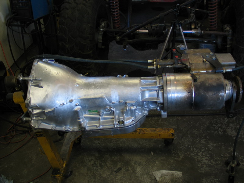 |
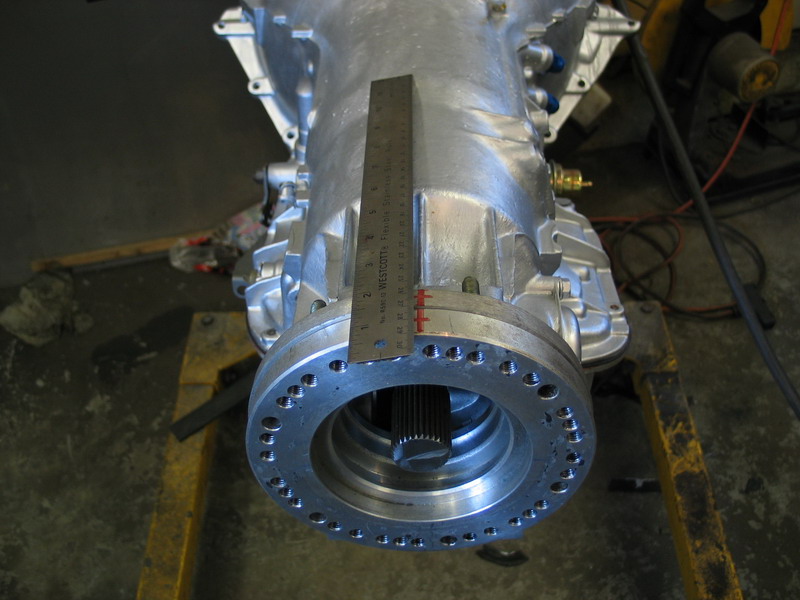
The TH400, Adapter (AS-6401), clocking ring 51-8603, and Atlas-4SP combo is 40-1/2" long from bellhousing to rear output flange.
|
||||||||||||||||||||||||||||||||||||||||||||||||||||
The following chart shows the total number of gear ratios available with my TH400 & Atlas-4SP setup, with the following parameters: Transmission: Stock TH400 3-speed automatic, with gear ratios:
Transfer Case: Atlas-4SP, with gear ratios:
Axle: Differential gear ratio (Ring & Pinion) - 4.10
|
|||||||||||||||||||||||||||||||||||||||||||||||||||||
|
|||||||||||||||||||||||||||||||||||||||||||||||||||||


 |
Sources: Advance Adapters (805) 238-7000 / (800) 350-2223 |
|

