 |
Advance Adapters 4-Speed Atlas Transfer Case By Bill "BillaVista" Ansell |
IntroductionAfter trying for far too long to get my old Dana 20 transfer case to live behind a healthy V8 driving a 203 doubler and spinning 42" TSL's I finally gave up. The little box served me well for many years, but lately, as both the trails I do and my driving style have been getting more extreme, it became obvious it was no longer up to the task. The first time it exploded was during my first competition - not a good start! After a re-build it let me down again during an annual trek to Paragon - frustrating and disappointing! It was time for a serious upgrade. |
 |
| I really liked the old doubler setup for both it's extreme compound-low and also for the number of gear selections available. Downsides were it's weight and length. I didn't want to switch to just a single case as I would lose gear-selection flexibility (particularly important for the wide variety of terrain I wheel). I also wanted to retain a super-low crawl ratio. And if I could save a few pounds and gain some driveshaft length in the bargain that would be awesome. It was a tall order but the recently released 4-speed Atlas (Atlas-4SP) looked like it might just be the perfect solution to my needs. | |
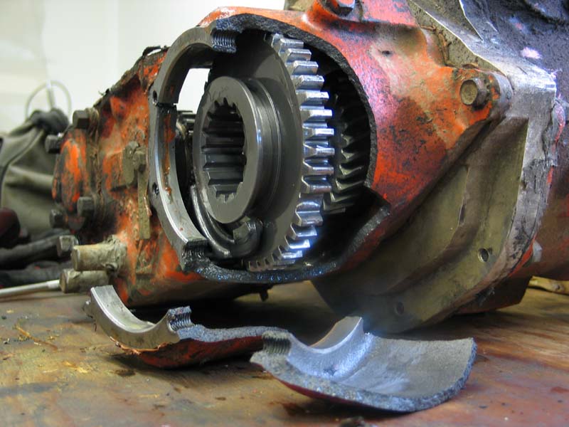 |
First case explosion. So much for my first competition! | ||||||||||||||||||||||||||||||||||||||||||||||||||||||||||||||||||||||||||||||||||||||||||||||||||||||||||||||||||||||||
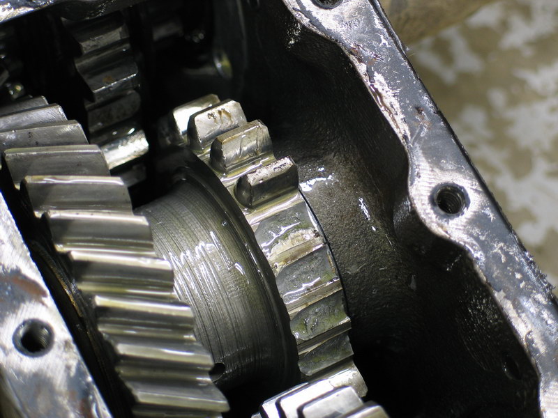 |
And again, the result of a hard climb. The little straight-cut spur gears on the Dana20 low-range and intermediate gears just aren't up to the task of pushing a 5000lb buggy on 42" tires up near-vertical rocky climbs! | ||||||||||||||||||||||||||||||||||||||||||||||||||||||||||||||||||||||||||||||||||||||||||||||||||||||||||||||||||||||||
About the Atlas-4SPThe Atlas-4SP was designed so that users could have ultra-low gearing for rock crawling, a low gear for trail use, and mid- and high-ranges for sand, mud, and street, all in a single, short, light, top-quality, custom-made, brand-new package. Sweet! That's exactly what I wanted. Here's a look at the basic data: CASE: INTERNAL COMPONENTS: RATIOS: LUBRICATION:
The Atlas-4SP is essentially two parts cleverly combined in a single compact package - like a doubler all in one. The first part is the planetary reduction assembly which is mated directly to the main case. The planetary reduction assembly is a New Process Gear design - the same used in the NP241-HD transfer case. This assembly has been rated to withstand 5,555 ft./lbs. of torque, and up to 11,000 lbs. gross vehicle weight. It has been used in many heavy-duty vehicles including the original H1 Military Hummer and one-ton Dodge trucks. The planetary is shifted separately from the transfer case via a cable or electronic shifter and has a low range of 2.72:1 and a high range of 1:1. The six-planetary design makes it quiet, strong, and easy to shift. However, the planetary is not a synchronized shift-on-the-fly design and must be operated when the vehicle is stopped. The main case of the 4SP is similar to the 2-speed Atlas but it does have some differences. All of the gears, with the exception of the input gear, are the same. The front output uses all of the same parts. The rear output shaft is different in the 4SP and different bearings are used in some spots. Both front and rear outputs are 32-spline standard. The main case of the 4SP is the same raw casting as the 2SP, but has some machining differences to make it into a 4SP. The main case functions independently from the planetary reduction assembly and retains all of the normal Atlas features such as: front and rear outputs controlled independently, the “front only” option, and synchronized shift-on-the-fly design. The main case can be shifted via standard twin-sticks or by the new cable shifters. It is available in either 2.0:1 or 3.8:1 low-range options. Combined with the planetary reduction assembly's 2.72:1 low range the available 4SP rations are 1:1, 2.0:1, 2.72:1, & 5.44:1 or 1:1, 2.72:1, 3.8:1, & 10.34:1. The 4SP mates directly to 21, 23, 27, 29, 31, 32 and 34 spline transmission outputs. It has a circular bolt pattern on the front, identical to the one found in Jeep vehicles. Advance Adapters has a variety of different adapters available to retrofit the 4SP into nearly any application. I used a combination of AA parts to fit mine neatly behind my old 10-spline SM465 4-speed manual transmission. The 4SP can also be custom-ordered with a dizzying array of options/configurations: CV or non-CV outputs, yokes or flanges, speedometer or VSS tail housings, ultra-short competition tail housing, left- or right-hand front output, cable, electric, or lever shift - the list is endless and each case is a custom unit built to your specifications. Rather than try to list each possible option or configuration I refer you instead to the Atlas Transfer Case Installation Guide that contains a wealth of information on everything from gear ratio options to custom rotations to input spline configurations and adapter selection. My Atlas-4SPTo fit my application I ordered the following:
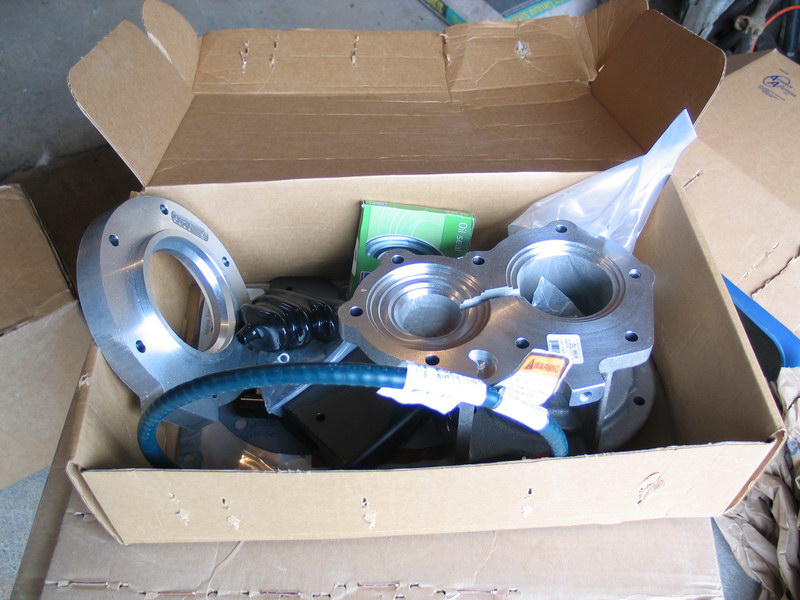
Here's what I got: |
|||||||||||||||||||||||||||||||||||||||||||||||||||||||||||||||||||||||||||||||||||||||||||||||||||||||||||||||||||||||||
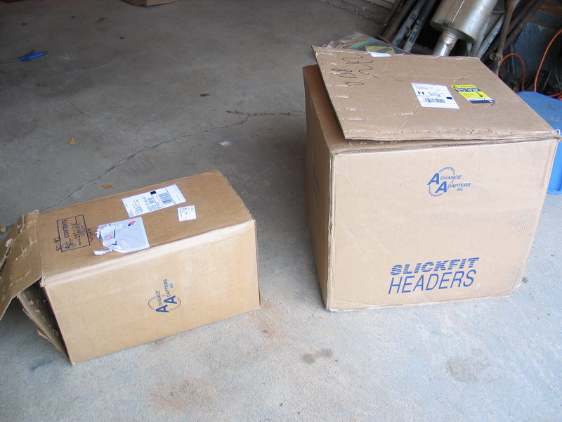 |
Two boxes arrived on the holiest of holy days! The large one on the right holds the Atlas-4SP and the smaller on the left has two more boxes inside with all the other bits in them. | ||||||||||||||||||||||||||||||||||||||||||||||||||||||||||||||||||||||||||||||||||||||||||||||||||||||||||||||||||||||||
 |
Everything was well packed and well protected. | ||||||||||||||||||||||||||||||||||||||||||||||||||||||||||||||||||||||||||||||||||||||||||||||||||||||||||||||||||||||||
 |
One of the smaller boxes contains the twin-stick cable shifters and the MTF (oil) for the case. | ||||||||||||||||||||||||||||||||||||||||||||||||||||||||||||||||||||||||||||||||||||||||||||||||||||||||||||||||||||||||
 |
The other was equally well packed... | ||||||||||||||||||||||||||||||||||||||||||||||||||||||||||||||||||||||||||||||||||||||||||||||||||||||||||||||||||||||||
 |
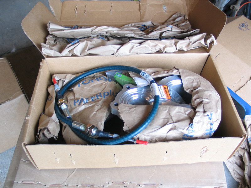
... and held the tranny to T-case adapter and the cable shifter for the planetary reduction box. | ||||||||||||||||||||||||||||||||||||||||||||||||||||||||||||||||||||||||||||||||||||||||||||||||||||||||||||||||||||||||
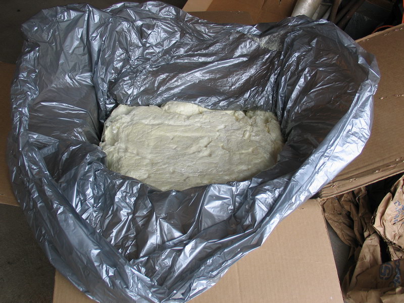 |
No chances are taken with the Atlas itself - it comes completely packed in foam. | ||||||||||||||||||||||||||||||||||||||||||||||||||||||||||||||||||||||||||||||||||||||||||||||||||||||||||||||||||||||||
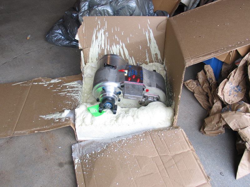 |
I had to cut the box apart to get it out. Nice! | ||||||||||||||||||||||||||||||||||||||||||||||||||||||||||||||||||||||||||||||||||||||||||||||||||||||||||||||||||||||||
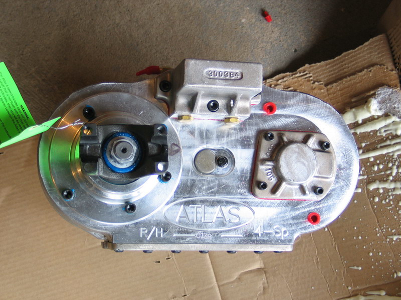 |
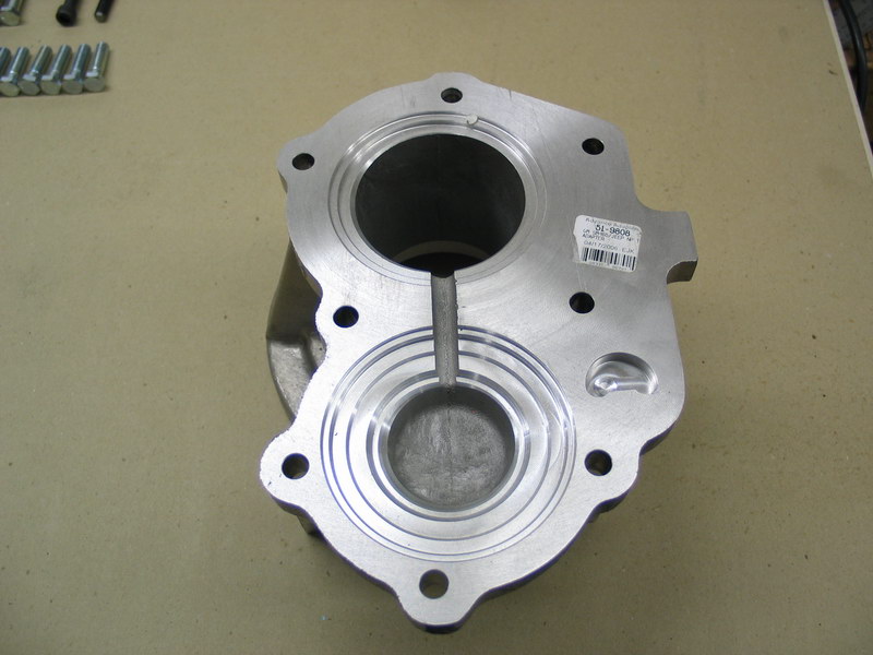
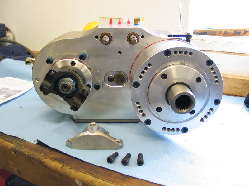
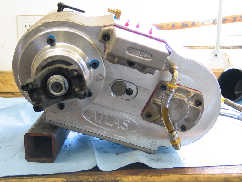
And then suddenly there it is! View from the back. Note engraving showing that it's a right-hand drop 4-speed Atlas. |
||||||||||||||||||||||||||||||||||||||||||||||||||||||||||||||||||||||||||||||||||||||||||||||||||||||||||||||||||||||||
 |
The green tag affixed to the rear output yoke warns the user that the case is shipped dry and must be filled with lube before operation. | ||||||||||||||||||||||||||||||||||||||||||||||||||||||||||||||||||||||||||||||||||||||||||||||||||||||||||||||||||||||||
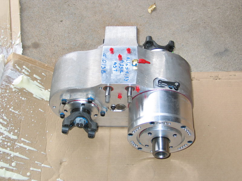 |
All the threaded holes and openings are covered with or plugged by red stoppers that keep debris out of the case during shipping and handling. | ||||||||||||||||||||||||||||||||||||||||||||||||||||||||||||||||||||||||||||||||||||||||||||||||||||||||||||||||||||||||
 |
It's really quite a work of art - even with all these pictures it's hard to appreciate the compactness or light weight until you see one up-close and in-person. | ||||||||||||||||||||||||||||||||||||||||||||||||||||||||||||||||||||||||||||||||||||||||||||||||||||||||||||||||||||||||
 |
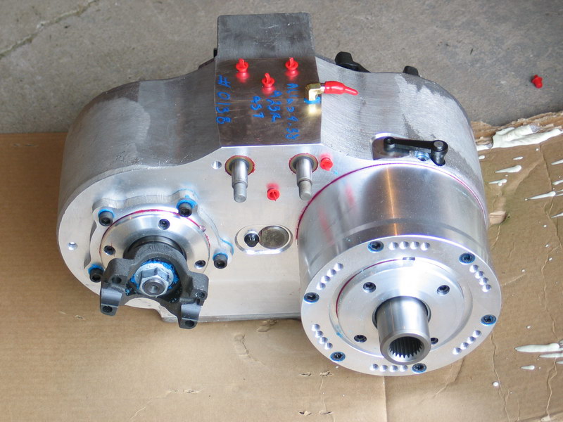
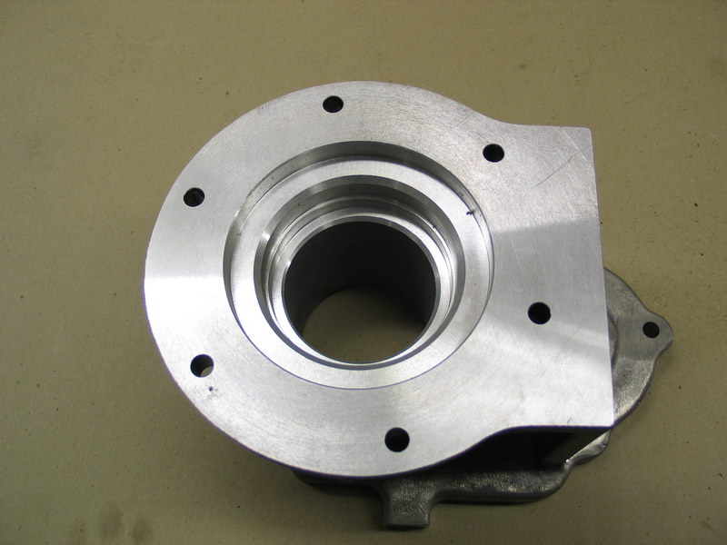
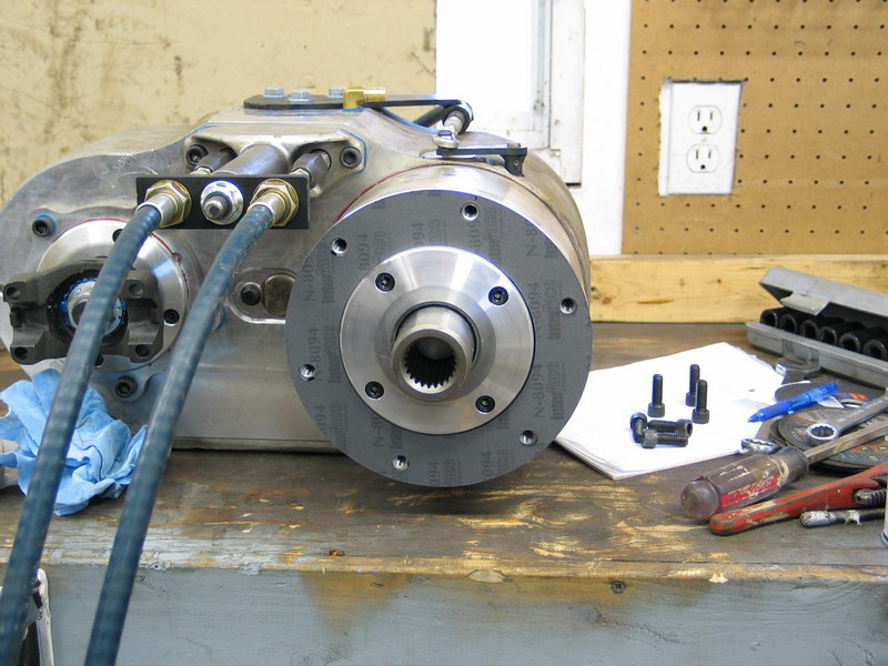
View from the front. | ||||||||||||||||||||||||||||||||||||||||||||||||||||||||||||||||||||||||||||||||||||||||||||||||||||||||||||||||||||||||
 |
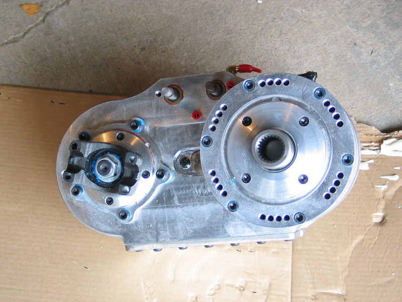
The underside of the unit showing the access cover and blue-anodized drain plug. | ||||||||||||||||||||||||||||||||||||||||||||||||||||||||||||||||||||||||||||||||||||||||||||||||||||||||||||||||||||||||
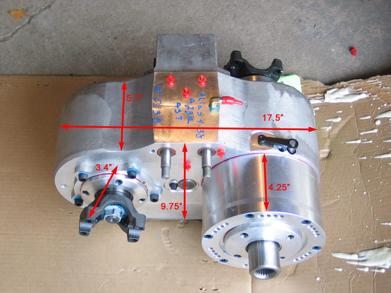 |
Atlas-4SP dimensions. | ||||||||||||||||||||||||||||||||||||||||||||||||||||||||||||||||||||||||||||||||||||||||||||||||||||||||||||||||||||||||
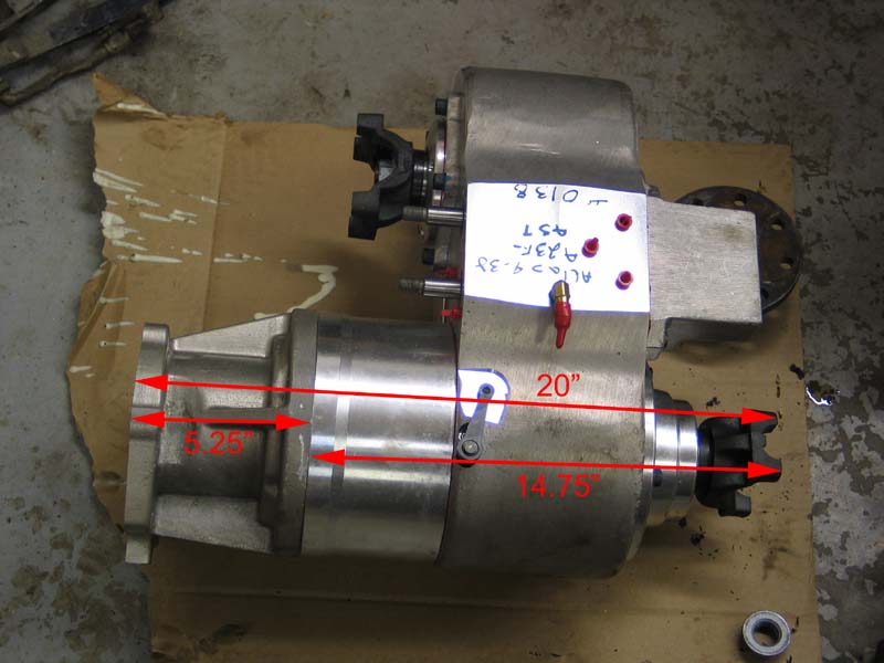 |
Atlas-4SP length with short tail housing (no speedometer) and 32-spline 1350 non-CV yoke. | ||||||||||||||||||||||||||||||||||||||||||||||||||||||||||||||||||||||||||||||||||||||||||||||||||||||||||||||||||||||||
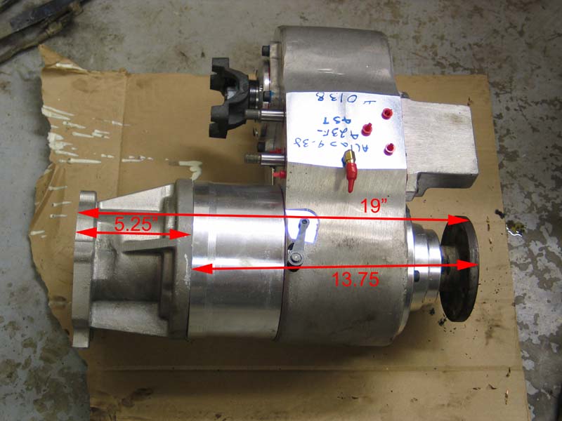 |
Atlas-4SP length with short tail housing (no speedometer) and 32-spline High Angle Driveline 1350 CV flange. | ||||||||||||||||||||||||||||||||||||||||||||||||||||||||||||||||||||||||||||||||||||||||||||||||||||||||||||||||||||||||
The PartsTwin-stick Cable Shifters |
|||||||||||||||||||||||||||||||||||||||||||||||||||||||||||||||||||||||||||||||||||||||||||||||||||||||||||||||||||||||||
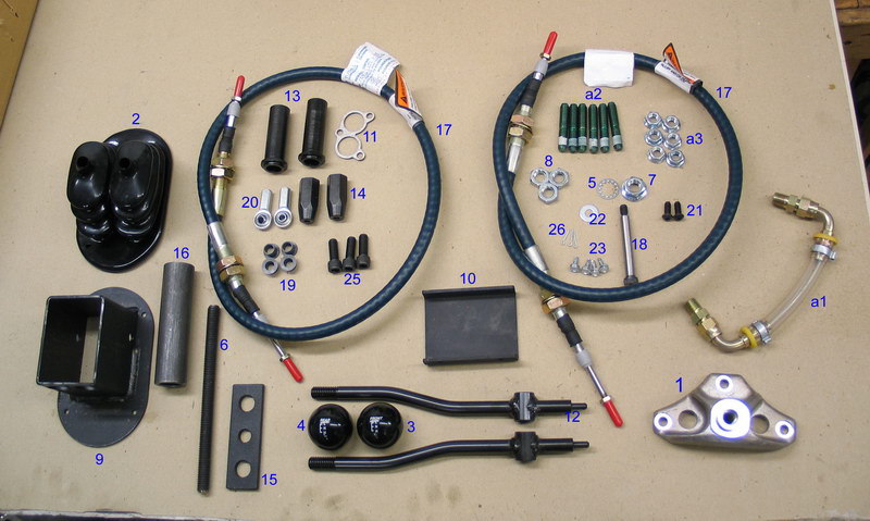 |
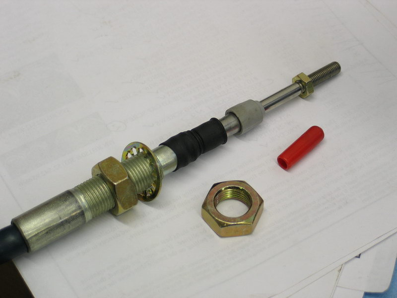
This is a layout of all the parts for the twin-stick cable shifters (for shifting the main case) plus the lubricant-level sight tube and the studs and nuts to mount the case to the transmission adapter. All the parts here, along with the supplied lubricant, Torco MTF, form the kit: part no. 303009. This kit is sold with the Atlas-4SP (included in the price) if you specify "cable shift" as an option. The parts key is below: |
||||||||||||||||||||||||||||||||||||||||||||||||||||||||||||||||||||||||||||||||||||||||||||||||||||||||||||||||||||||||
Key:
|
|||||||||||||||||||||||||||||||||||||||||||||||||||||||||||||||||||||||||||||||||||||||||||||||||||||||||||||||||||||||||
 |
This is the transfer case lubricant that is recommended for the Atlas 4-SP and is supplied with unit. You're supposed to get 2 quarts if you order a regular 2-speed Atlas (capacity 2 qts) and 3 quarts if you order a 4-speed Atlas (capacity 2.5 qts). For some reason I only received 2 quarts with my Atlas-4SP. | ||||||||||||||||||||||||||||||||||||||||||||||||||||||||||||||||||||||||||||||||||||||||||||||||||||||||||||||||||||||||
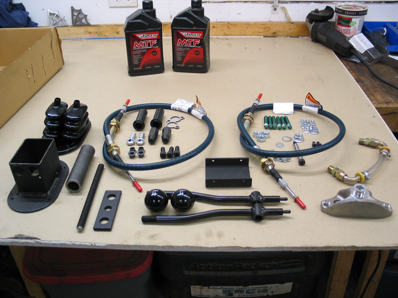 |
The complete kit, part number 303009. | ||||||||||||||||||||||||||||||||||||||||||||||||||||||||||||||||||||||||||||||||||||||||||||||||||||||||||||||||||||||||
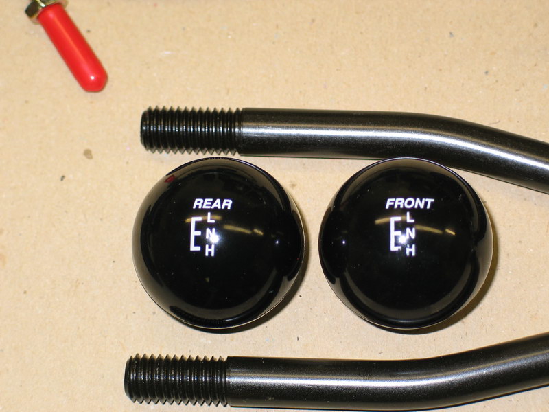 |
Close-up of the shift knobs. | ||||||||||||||||||||||||||||||||||||||||||||||||||||||||||||||||||||||||||||||||||||||||||||||||||||||||||||||||||||||||
 |
Close-up, parts of kit 303009. | ||||||||||||||||||||||||||||||||||||||||||||||||||||||||||||||||||||||||||||||||||||||||||||||||||||||||||||||||||||||||
 |
Close-up , parts of kit 303009. | ||||||||||||||||||||||||||||||||||||||||||||||||||||||||||||||||||||||||||||||||||||||||||||||||||||||||||||||||||||||||
Reduction Box Cable Shifter |
|||||||||||||||||||||||||||||||||||||||||||||||||||||||||||||||||||||||||||||||||||||||||||||||||||||||||||||||||||||||||
 |
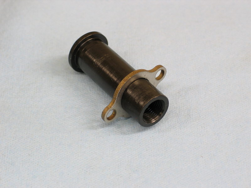
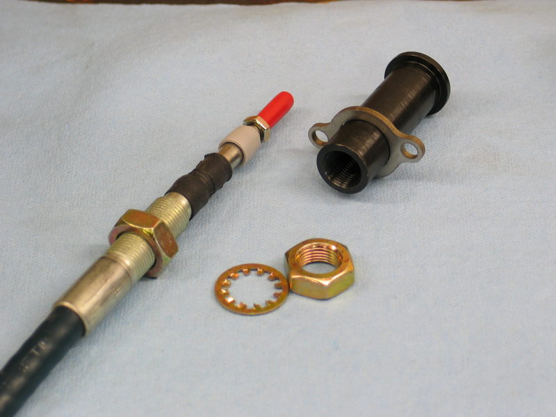
This shows all the parts of the cable-shift mechanism for the planetary reduction box. This kit, for right-hand drop cases, is sold as part no. 344020R. It is sold separately from the Atlas-4SP, presumably because a differently priced electronic-shift kit is optionally available. Parts key below. |
||||||||||||||||||||||||||||||||||||||||||||||||||||||||||||||||||||||||||||||||||||||||||||||||||||||||||||||||||||||||
Key:
|
|||||||||||||||||||||||||||||||||||||||||||||||||||||||||||||||||||||||||||||||||||||||||||||||||||||||||||||||||||||||||
 |
Close-up of 4-speed reduction box shift knob, part number 340607. | ||||||||||||||||||||||||||||||||||||||||||||||||||||||||||||||||||||||||||||||||||||||||||||||||||||||||||||||||||||||||
Adapter |
|||||||||||||||||||||||||||||||||||||||||||||||||||||||||||||||||||||||||||||||||||||||||||||||||||||||||||||||||||||||||
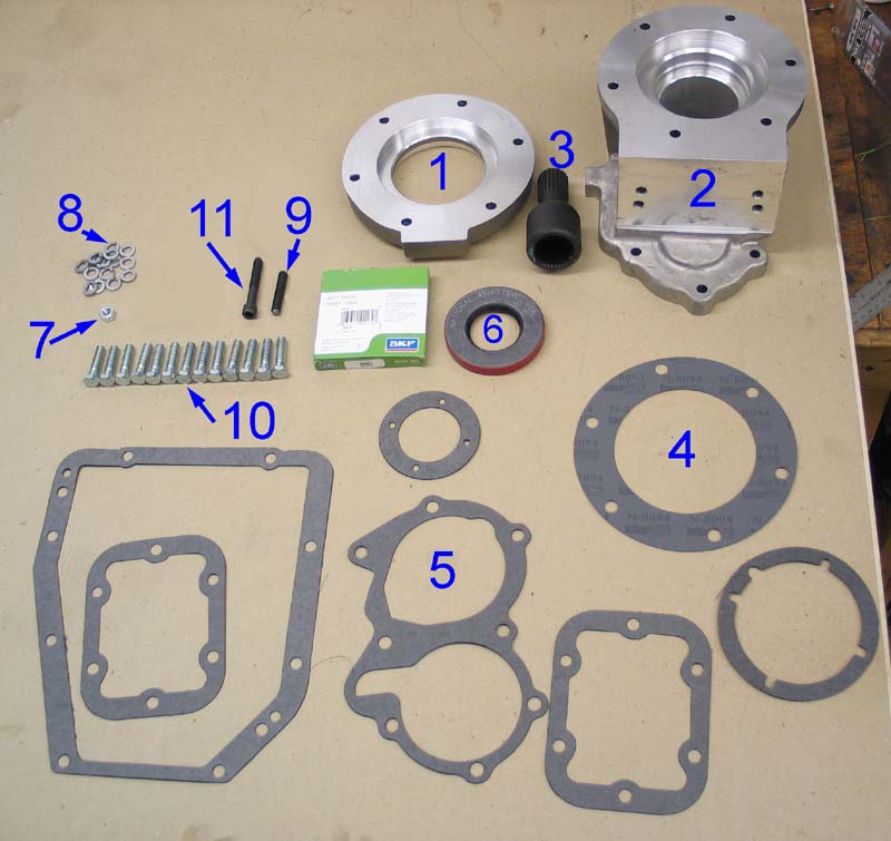 |
This picture shows the complete adapter kit part no. 50-9808. This kit is sold as "GM Truck 4WD 4SP Model SM465 10 Spline to Jeep NP231 23 Spline Transfer Case (short design)" As you can tell from the name - it was originally designed to retrofit the SM465 4-speed tranny into a Jeep. Recall that the Atlas-4SP is only available in input splines 21, 23, 27, 29, 31, 32 and 34 - essentially NVG input spline counts because of the NVG 6-planetary design reduction box on the front of the Atlas 4-SP. That's why this SM465 to Jeep 23 Spline transfer case adapter kit is the ideal kit to fit the Atlas-4SP behind my 10-spline SM465 and is also why I ordered the Atlas-4SP with 23-spline input. Because I'm using it to fit an Atlas-4SP behind an SM465 as opposed to using it to fit an SM465 into a Jeep there are a few parts I didn't use. These are identified in the parts key below. The kit also includes a number of gaskets that aren't strictly needed (unnumbered in the pic at left) - a full set for overhauling the SM465 - but they're nice to have in case you're rebuilding your tranny at the same time. |
||||||||||||||||||||||||||||||||||||||||||||||||||||||||||||||||||||||||||||||||||||||||||||||||||||||||||||||||||||||||
Key:
|
|||||||||||||||||||||||||||||||||||||||||||||||||||||||||||||||||||||||||||||||||||||||||||||||||||||||||||||||||||||||||
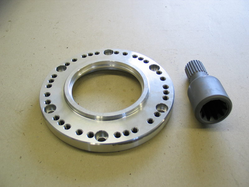 |
Now, just to confuse things ever-so-slightly. This is a pic of the spacer adapter that I used instead of the one that came with kit 50-9808. The spacer adapter goes between the Atlas-4SP and the tranny-to-Atlas adapter, for reasons we shall cover shortly. The point to be made here is that you could use the spacer adapter that comes with the kit (part no. 51-0404, identified as item #2 in the preceding picture). Or, as I discovered (with the help of Vic at Advance Adapters!) you can substitute the spacer adapter pictured at left. It is part no. 51-8603 which normally comes with the "Jeep AX15 5 Speed to Jeep Dana 300 Transfer Case" adapter kit (kit part no. 50-8603). The advantages of using 51-8603 (left) instead of 51-0404 (above) is that it is 1/4" shorter and, more importantly, has five (5) different bolt patterns drilled in it. Since this goes between the tranny adapter and the Atlas it provides a number of different clocking options that wouldn't otherwise be available. This picture shows the side that mates to the tranny adapter... |
||||||||||||||||||||||||||||||||||||||||||||||||||||||||||||||||||||||||||||||||||||||||||||||||||||||||||||||||||||||||
 |
... and this is the side that mates to the front of the Atlas-4SP. | ||||||||||||||||||||||||||||||||||||||||||||||||||||||||||||||||||||||||||||||||||||||||||||||||||||||||||||||||||||||||
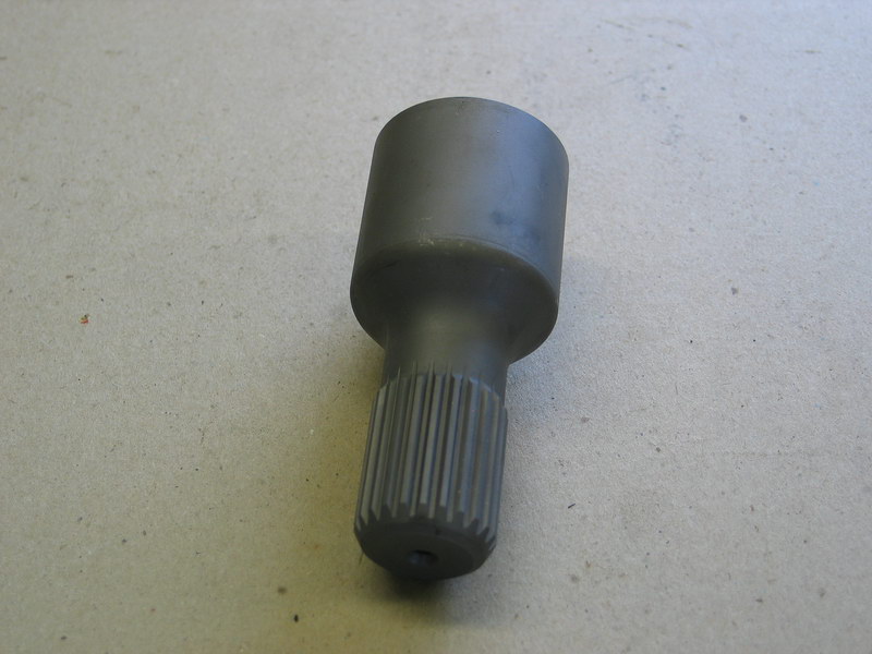 |
Close-up of part no. 52-9700, the 10-spline internal x 23-spline external spud shaft that connects the SM465's 10-spline output to the 23-spline input of the Atlas-4SP. It is a "floating" design, mounting between transmission and transfer case within the transmission to Atlas adapter casting. |
||||||||||||||||||||||||||||||||||||||||||||||||||||||||||||||||||||||||||||||||||||||||||||||||||||||||||||||||||||||||
 |
The next four pics show the transmission-to-Atlas adapter, part number 51-9808. It is cast aluminum, machine finished, and measures 5.25" long. In this pic the the transmission would mount on the right, and the Atlas transfer case on the left. |
||||||||||||||||||||||||||||||||||||||||||||||||||||||||||||||||||||||||||||||||||||||||||||||||||||||||||||||||||||||||
 |
Transmission side of the adapter - clearly showing the Chevy SM465 "figure-8" bolt pattern. | ||||||||||||||||||||||||||||||||||||||||||||||||||||||||||||||||||||||||||||||||||||||||||||||||||||||||||||||||||||||||
 |
Atlas side of the adapter. | ||||||||||||||||||||||||||||||||||||||||||||||||||||||||||||||||||||||||||||||||||||||||||||||||||||||||||||||||||||||||
 |
The adapter includes a machined-flat bottom for mounting along with a threaded hole (red arrow) that can be used for a "torque control arm" (more on this later). As you can see in this picture, the adapter's flat bottom has four pre-drilled and threaded holes - doubtless useful for mounting in stock vehicles for which the part was originally designed - i.e. for when it is used to swap an SM465 into a Jeep. The holes are 3/8"-NC16. One pair are approximately 4.25" apart and the other 4-7/16" apart. I ended up not using either and fabricated a different mount system as we shall see a little later. |
||||||||||||||||||||||||||||||||||||||||||||||||||||||||||||||||||||||||||||||||||||||||||||||||||||||||||||||||||||||||
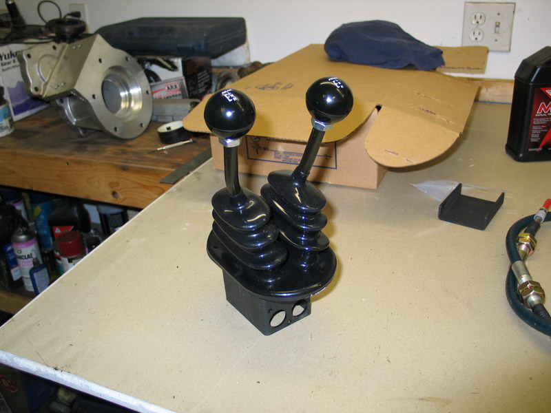 |
A first look at the main case's twin-stick shifters. | ||||||||||||||||||||||||||||||||||||||||||||||||||||||||||||||||||||||||||||||||||||||||||||||||||||||||||||||||||||||||
New vs. Old |
|||||||||||||||||||||||||||||||||||||||||||||||||||||||||||||||||||||||||||||||||||||||||||||||||||||||||||||||||||||||||
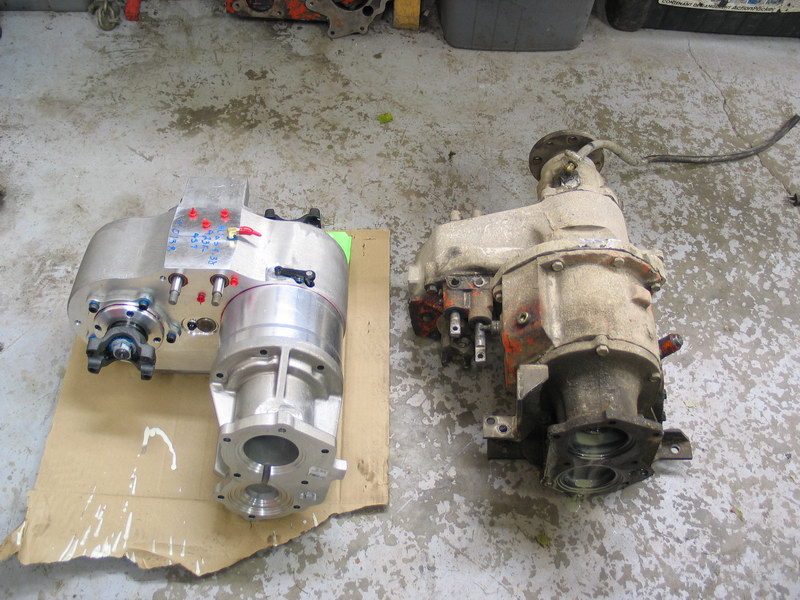 |
This next series of four pics shows a comparison between the new Atlas-4SP and my old NP203/Dana 20 doubler. The new Atlas-4SP is about 4" shorter, 70 lbs lighter, and provides a lowest gear ratio of 10.34:1 vice 4:1 for the doubler. |
||||||||||||||||||||||||||||||||||||||||||||||||||||||||||||||||||||||||||||||||||||||||||||||||||||||||||||||||||||||||
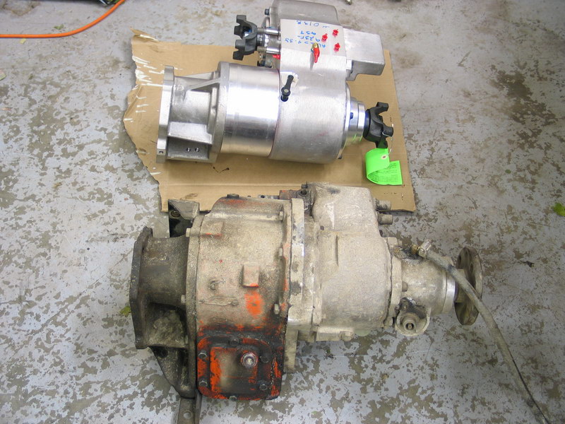 |
The Atlas weighs 128 lbs as pictured, the old doubler setup 198 lbs!!! | ||||||||||||||||||||||||||||||||||||||||||||||||||||||||||||||||||||||||||||||||||||||||||||||||||||||||||||||||||||||||
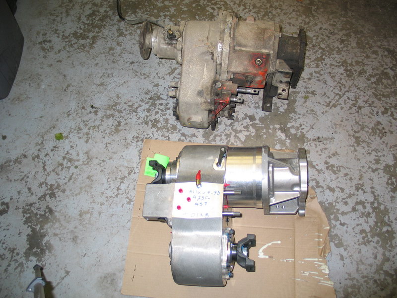 |
It's shinier too! | ||||||||||||||||||||||||||||||||||||||||||||||||||||||||||||||||||||||||||||||||||||||||||||||||||||||||||||||||||||||||
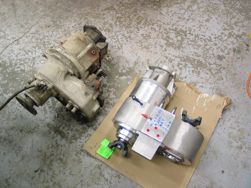 |
Despite being shorter and lighter, comparing the relative sizes of the main cases gives some indication of how much stronger the Atlas will be. Not to mention that the Atlas gears are all helical-cut as opposed to those accursed spur-cut gears in the Dana 20. | ||||||||||||||||||||||||||||||||||||||||||||||||||||||||||||||||||||||||||||||||||||||||||||||||||||||||||||||||||||||||
Installing the Adapter |
|||||||||||||||||||||||||||||||||||||||||||||||||||||||||||||||||||||||||||||||||||||||||||||||||||||||||||||||||||||||||
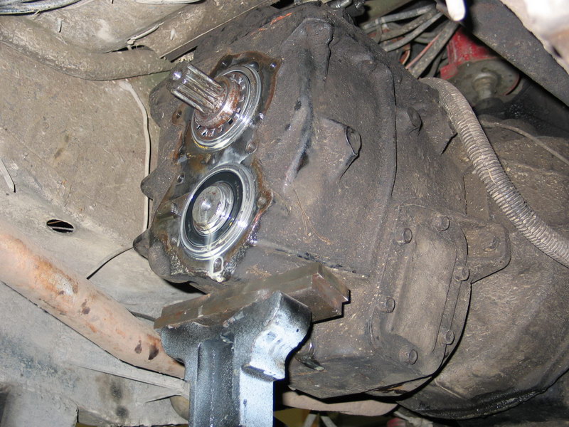 |
With the old stock Chevy adapter removed, the back of the SM465 looks like this. Make sure to give the mounting surface a good cleaning. |
||||||||||||||||||||||||||||||||||||||||||||||||||||||||||||||||||||||||||||||||||||||||||||||||||||||||||||||||||||||||
 |
The 10 x 23 spud shaft just slips on the SM465 output shaft. The instructions from AA don't mention it, but I smeared a good coating of lubricant inside the female splines before slipping the spud shaft in place. I used good old Permatex anti-seize - the gray"high temp" grease. I just feel that any dry metal-to-metal contact should be avoided if possible and there isn't a good technical reason to exclude lubricant. |
||||||||||||||||||||||||||||||||||||||||||||||||||||||||||||||||||||||||||||||||||||||||||||||||||||||||||||||||||||||||
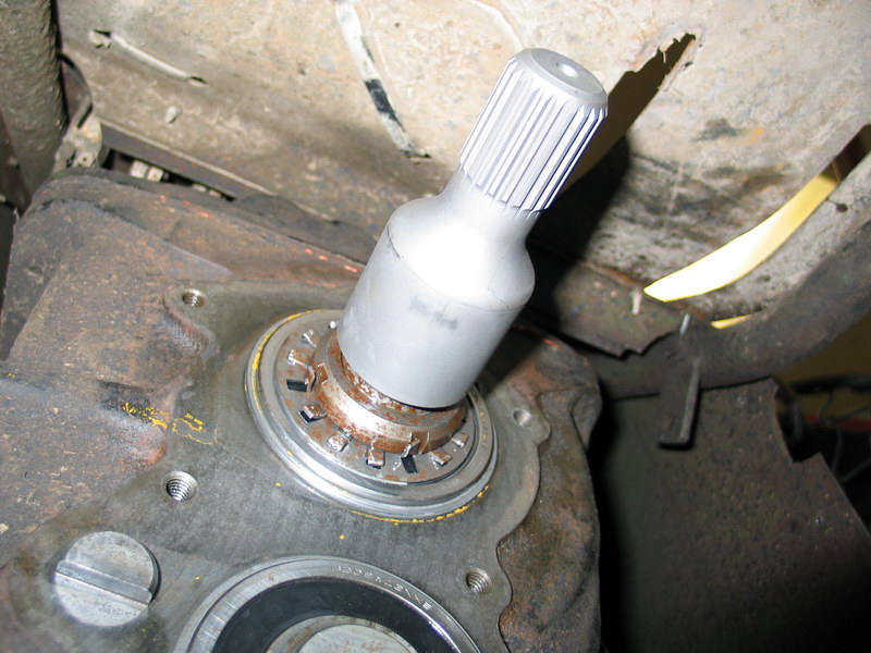 |
The spud shaft in place on the transmission output shaft. | ||||||||||||||||||||||||||||||||||||||||||||||||||||||||||||||||||||||||||||||||||||||||||||||||||||||||||||||||||||||||
 |
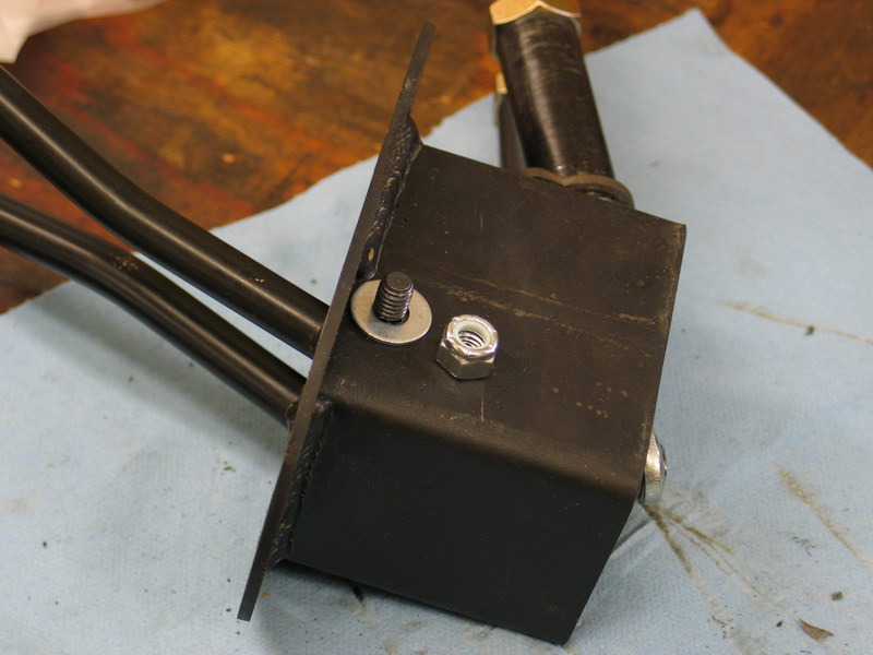
The adapter is held in place with seven of the twelve 3/8"-NC16 x 1-1/2" hex head cap screws (bolts) (pn 723723) and the 3/8"-NC16 x 2" stud (pn 723711) with the 3/8"-NC16 hex nut (pn 723701). Eight 3/8" lock washers are also used (pn 723704) This pic illustrates why the stud is used. Due to the shape of the adapter, the top-most hole (the one at "12 'o'clock" doesn't have sufficient clearance for a bolt to be inserted. |
||||||||||||||||||||||||||||||||||||||||||||||||||||||||||||||||||||||||||||||||||||||||||||||||||||||||||||||||||||||||
 |
Instead, the stud is inserted into the top-most hole first, before the adapter is fitted in place. I used some blue Loctite thread-locker on the stud before installation, as well as on all the bolt threads. Before fitting the adapter in place I also "glued" the gasket to the transmission using Permatex spray-a-gasket sealant. |
||||||||||||||||||||||||||||||||||||||||||||||||||||||||||||||||||||||||||||||||||||||||||||||||||||||||||||||||||||||||
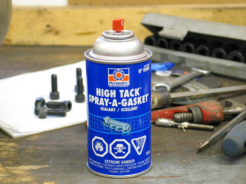 |
This is the stuff. It's just a fancy spray adhesive for holding gaskets in place. | ||||||||||||||||||||||||||||||||||||||||||||||||||||||||||||||||||||||||||||||||||||||||||||||||||||||||||||||||||||||||
 |
Alternatively you could glue the gasket to the adapter before installation. | ||||||||||||||||||||||||||||||||||||||||||||||||||||||||||||||||||||||||||||||||||||||||||||||||||||||||||||||||||||||||
 |
Fit the adapter in place and secure with the remaining 7 bolts and lock-washers. Use blue Loctite on the bolt threads and tighten to approx. 30 ft/lbs. Don't forget to install the nut on the stud, use a little Loctite on the threads, and also tighten it to 30 ft/lbs. |
||||||||||||||||||||||||||||||||||||||||||||||||||||||||||||||||||||||||||||||||||||||||||||||||||||||||||||||||||||||||
 |
The installed adapter looks like this. | ||||||||||||||||||||||||||||||||||||||||||||||||||||||||||||||||||||||||||||||||||||||||||||||||||||||||||||||||||||||||
 |
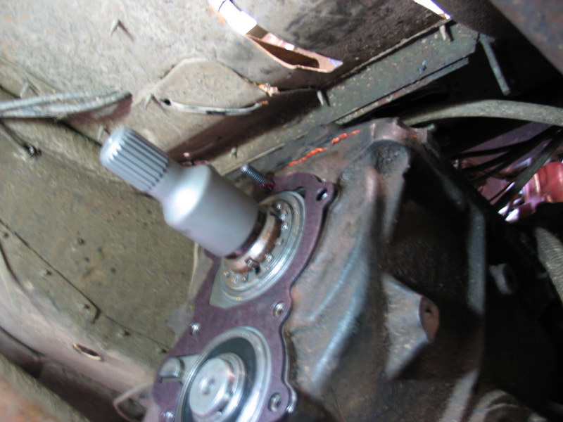
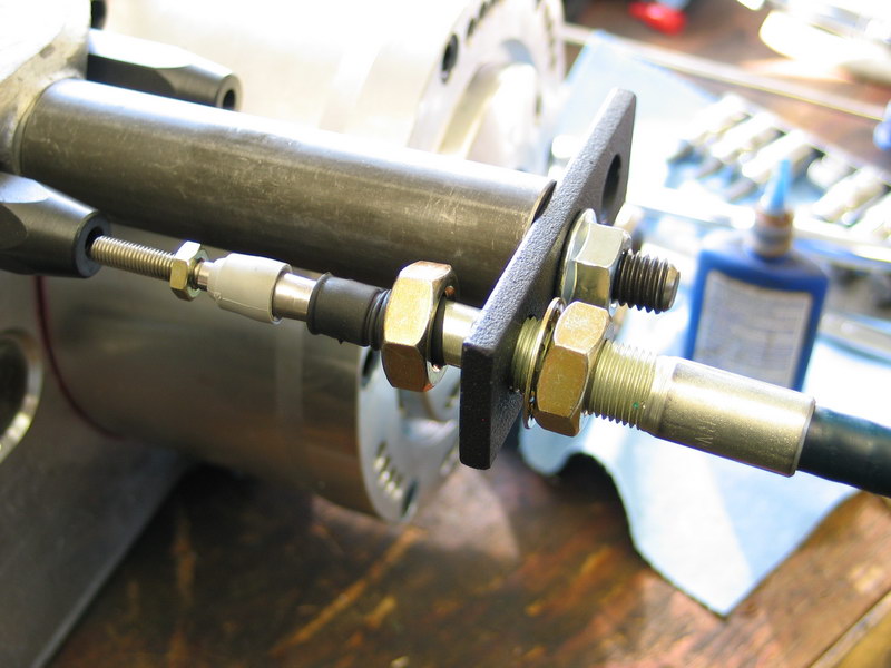
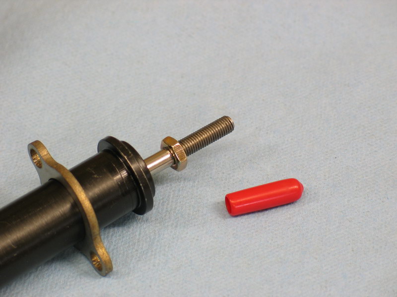
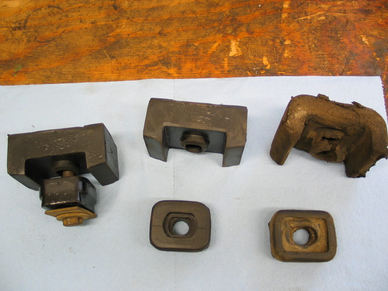
This picture illustrates why the spacer adapter is required between the adapter and the Atlas. You can see that the tip of the spud shaft protrudes just a fraction beyond the mounting face of the adapter. The Atlas-4SP CAN NOT accept any kind of positive "stick-out" like this. Installing the Atlas-4SP to any output shaft with positive stick-out will cause the shaft to bottom out in the Atlas input and damage the transfer case. Many other transmissions and/or adapters also have positive stick-out and, in most cases, any required spacer adapter can be obtained free from AA when the Atlas is purchased. |
||||||||||||||||||||||||||||||||||||||||||||||||||||||||||||||||||||||||||||||||||||||||||||||||||||||||||||||||||||||||
Preparing the Atlas-4SP for installationThe Atlas-4SP is not shipped completely ready to be installed. You must complete final assembly on the bench , and also fill it with lubricant before installing it. It's also a good idea to test and adjust the shifters before installation too. The supplied instructions are quite good in that they are thorough and cover everything. That said, they could certainly use a little improvement as you actually have to jump back-and forth between four different instruction books/sheets, and do so in a seemingly random order. Also, most of the included pictures (and there aren't very many) are fairly small, black&white, and quite fuzzy. No matter - I will now outline for you in complete detail (some might say painful detail!) every step of the process, in order. Of course, it's entirely possible to do things successfully in a different order - mine is not the only way (as my boss is fond of reminding me!). However, if you proceed in this order at least you know you won't go wrong or miss anything. I know this because along the way, as is my usual habit, I pretty much screwed up anything and everything that could be screwed up - but at least I can help you avoid any pitfalls. |
|||||||||||||||||||||||||||||||||||||||||||||||||||||||||||||||||||||||||||||||||||||||||||||||||||||||||||||||||||||||||
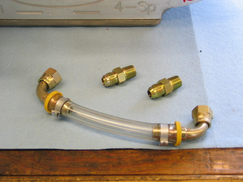 |
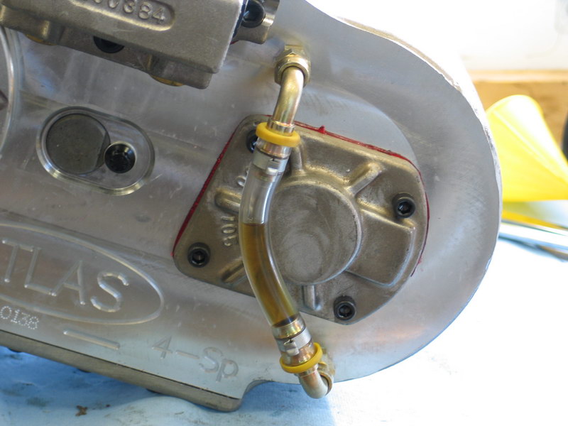
The first task is to install the oil-level sight tube. The tube itself comes crimped onto two 90° AN-6 JIC swivel fittings, and there are two 1/4" NPT to AN-6 male adapter fittings. On these fittings, the tapered threads (to the right in this picture) are the NPT threads that thread into the case. It fits in place behind the rear-cover of the front output shaft. |
||||||||||||||||||||||||||||||||||||||||||||||||||||||||||||||||||||||||||||||||||||||||||||||||||||||||||||||||||||||||
 |
Remove the two small red dust-plugs from the threaded holes. | ||||||||||||||||||||||||||||||||||||||||||||||||||||||||||||||||||||||||||||||||||||||||||||||||||||||||||||||||||||||||
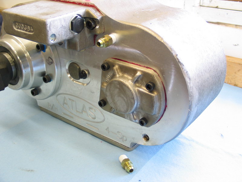 |
Tape the NPT threaded ends of the adapter fittings with Teflon tape or coat with pipe sealant, then thread them carefully into the case and tighten. | ||||||||||||||||||||||||||||||||||||||||||||||||||||||||||||||||||||||||||||||||||||||||||||||||||||||||||||||||||||||||
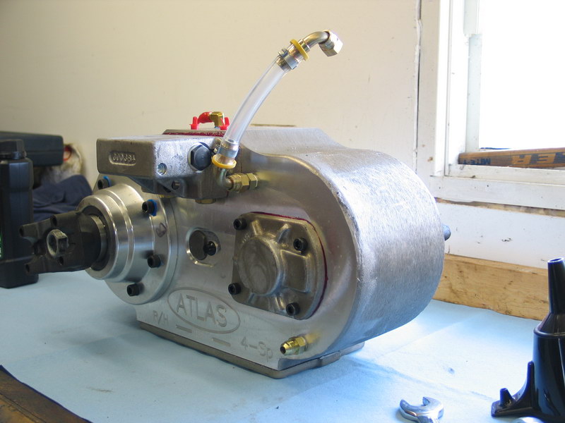 |
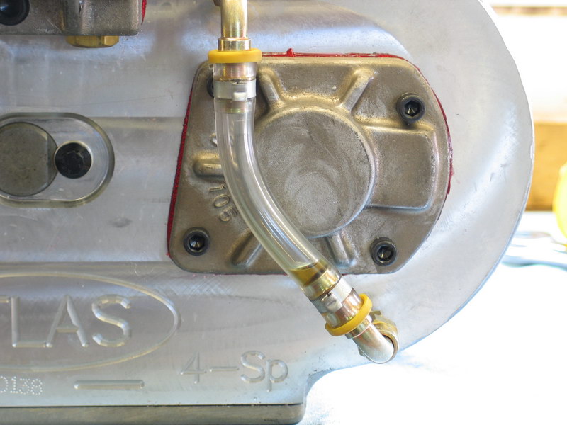
The swivel fittings of the sight tube are then tightened in place on the adapters. No Teflon tape nor pipe sealant is required nor should it be used on these JIC fittings. Because the next task is to fill the case with oil, and you do that through the upper sight tube fitting, you actually want to attach just the lower fitting first, despite what this picture shows. Remember what I said about cocking up anything and everything possible along the way? I swear, it's a God-given talent of mine! |
||||||||||||||||||||||||||||||||||||||||||||||||||||||||||||||||||||||||||||||||||||||||||||||||||||||||||||||||||||||||
 |
The recommended lubricant is the supplied Torco MTF. However, AA also recommend initially using one of the alternate engine-oil lubricants for the first 500-mile break-in of the transfer case. I chose Castrol Syntec SAE 5W-50, but you can also use Valvoline Synthetic 20w-50 or Mobil 1 Synthetic 15w-50. I will probably continue to run the Castrol Syntec even after break-in as the Torco MTF isn't available locally whereas the Castrol is available everywhere. Also, if I ever suffered a partial lubricant loss, especially somewhere where the Torco MTF isn't available, I'd rather not have to drain and flush the case before topping up (mixing different lubricants isn't a good idea). If I stick with the Castrol I'll be safe. |
||||||||||||||||||||||||||||||||||||||||||||||||||||||||||||||||||||||||||||||||||||||||||||||||||||||||||||||||||||||||
How to fill the Atlas-4SP isn't completely obvious. This actually raises one of the very few critique points I have for the Atlas-4SP - it doesn't have a fill port, and the filling procedure is a little unwieldy. When you initially fill the case with lubricant you do so by adding a specific amount of lubricant, rather than the more traditional method of filling a case to a specific point (usually until oil flows from the fill port.) This is because the Atlas has no fill port, and instead uses a sight-tube for proper oil-level verification. However, since the case can be installed at many different angles (rotations), and each rotation will cause the oil in the sight tube to sit at a different level, it's not possible for the sigh tube to be marked for correct level at the factory. Instead, you fill the case with the exact amount of lubricant required, install the case at the chosen rotation, and THEN mark the proper level on the sight tube for later visual verification of proper oil level. More on this later - for now we need to get 2.5 qts (2.36 L) of oil into the case and then tip it on it's front to ensure the lubricant flows into the reduction box. |
|||||||||||||||||||||||||||||||||||||||||||||||||||||||||||||||||||||||||||||||||||||||||||||||||||||||||||||||||||||||||
 |
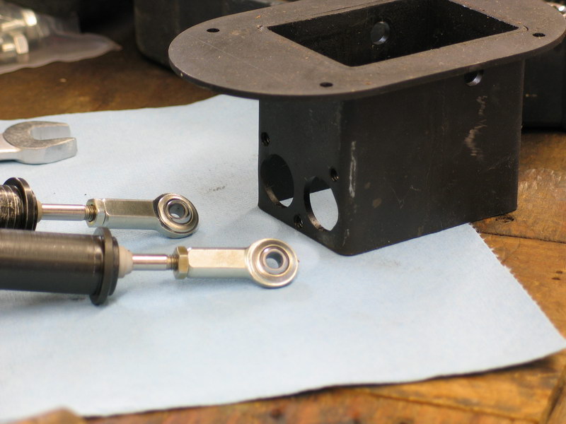
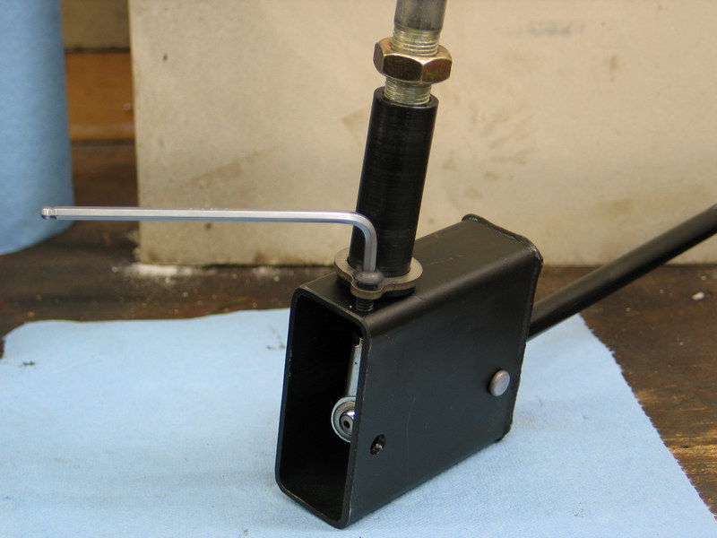
Because you need to tip the case onto its front after filling (or fill it while it's on its front) the first thing you need to do is install the twin-stick base mount because the mounting holes pass through into the case and if the bolts aren't installed oil can leak out of them. This would be a particular nuisance because we're adding a specific volume of oil in order to establish the right level on the sight tube. If you were to begin filling the case with the carefully measured 2.36 liters of fluid only to find some has leaked out during the process you pretty much have to drain the case, re-measure 2.36 liters and start again. Imagine how I know this! The twin-stick base mount (pn 302051) along with its three 3/8"-NC16 x 1" socket head cap screws (pn 723731) are shown in the foreground of this picture. |
||||||||||||||||||||||||||||||||||||||||||||||||||||||||||||||||||||||||||||||||||||||||||||||||||||||||||||||||||||||||
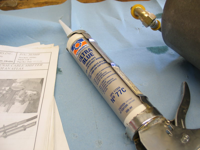 |
Because the mounting holes pass through into the case the mounting screws must have a little RTV sealant applied to their threads prior to installation. I used Permatex Ultra Blue. | ||||||||||||||||||||||||||||||||||||||||||||||||||||||||||||||||||||||||||||||||||||||||||||||||||||||||||||||||||||||||
 |
Apply a dab of blue RTV to the threads of the mounting screws. | ||||||||||||||||||||||||||||||||||||||||||||||||||||||||||||||||||||||||||||||||||||||||||||||||||||||||||||||||||||||||
 |
Slide the twin-stick base mount over the shift rails, install the mounting screws, and tighten. | ||||||||||||||||||||||||||||||||||||||||||||||||||||||||||||||||||||||||||||||||||||||||||||||||||||||||||||||||||||||||
You can now fill the case with the required lubricant. There is a note on oil filling towards the end of the planetary box cable shifter instruction sheet that reads: "After installing the sight tube per the instructions in the Atlas manual, add 2-1/2 quarts of included oil while still on the bench. After adding oil and before installing transfer case into vehicle, tip the transfer case onto the input shaft so that the rear yoke points straight up. This establishes the correct amount of oil in the planetary's separate reservoir" Note that this instruction says to fill with "included oil" which actually contradicts point 12 on page 2 of the "Atlas Transfer Case" instruction sheet which says to use an alternate motor-oil for the initial 500 mile break-in procedure. I assumed that the latter was correct. In any case, I chose to just fill the case while on its front. |
|||||||||||||||||||||||||||||||||||||||||||||||||||||||||||||||||||||||||||||||||||||||||||||||||||||||||||||||||||||||||
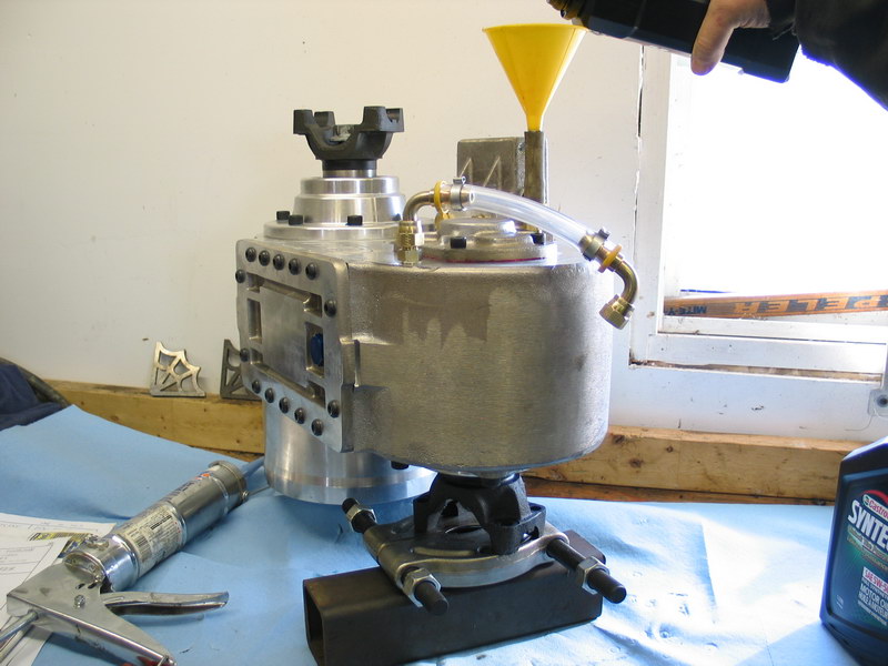 |
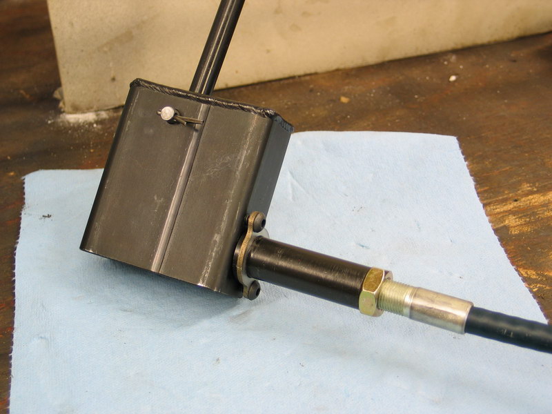
Stand the case on its front so the rear output shaft points straight up as shown in the pic and block it in place. In order to fill it I disconnected the upper end of the sight tube and installed a short length of rubber tube connected to a funnel with a small-diameter neck over the fitting in the case. Add the correct volume of oil. |
||||||||||||||||||||||||||||||||||||||||||||||||||||||||||||||||||||||||||||||||||||||||||||||||||||||||||||||||||||||||
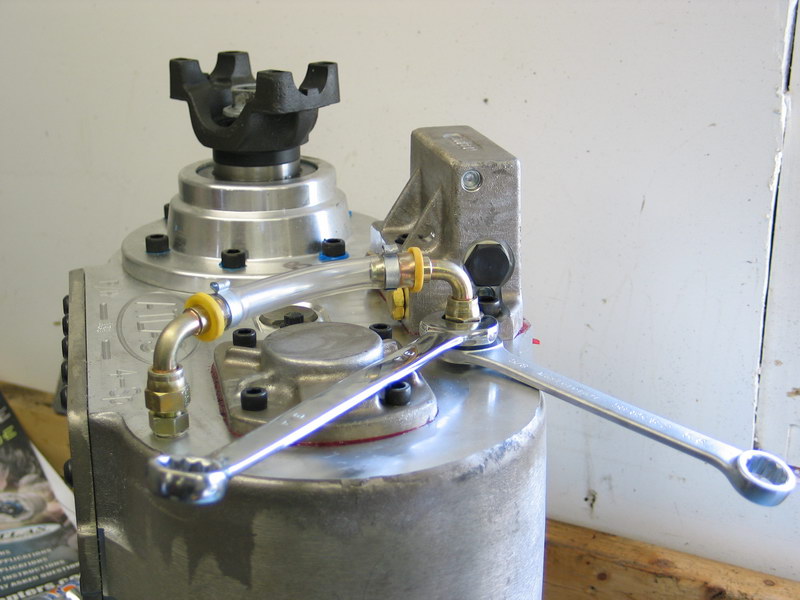 |
Once the case has been filled, re-attach and tighten the sight-tube fittings. Be sure to hold the adapter fitting with a wrench while tightening the swivel fitting, as shown. | ||||||||||||||||||||||||||||||||||||||||||||||||||||||||||||||||||||||||||||||||||||||||||||||||||||||||||||||||||||||||
 |
Here the case is filled and is being tilted to simulate different installed rotations to illustrate how this affects the level of the oil in the sight tube. | ||||||||||||||||||||||||||||||||||||||||||||||||||||||||||||||||||||||||||||||||||||||||||||||||||||||||||||||||||||||||
 |
In this pic the case is simulating being installed at a fairly large angle, and you can see the level of the oil is quite high in the tube. | ||||||||||||||||||||||||||||||||||||||||||||||||||||||||||||||||||||||||||||||||||||||||||||||||||||||||||||||||||||||||
 |
At the other extreme, if you were to install the case clocked perfectly flat you can see that the oil level barely shows in the sight tube. When the case is installed in the vehicle a permanent marker or small zip-tie will be used to mark the "full" level on the sight tube. |
||||||||||||||||||||||||||||||||||||||||||||||||||||||||||||||||||||||||||||||||||||||||||||||||||||||||||||||||||||||||
| With the case filled and the sight tube installed, it's time to complete the installation of the twin-stick cable shifters and bench test / adjust the shifters. This would be equally true if you were using manual shifters as opposed to cable shifters. | |||||||||||||||||||||||||||||||||||||||||||||||||||||||||||||||||||||||||||||||||||||||||||||||||||||||||||||||||||||||||
 |
Apply a little thread locker to the threads of the shift rails... | ||||||||||||||||||||||||||||||||||||||||||||||||||||||||||||||||||||||||||||||||||||||||||||||||||||||||||||||||||||||||
 |
...like so. | ||||||||||||||||||||||||||||||||||||||||||||||||||||||||||||||||||||||||||||||||||||||||||||||||||||||||||||||||||||||||
 |
Thread the shift rail adapters (pn 303306) on the shift rails and tighten. | ||||||||||||||||||||||||||||||||||||||||||||||||||||||||||||||||||||||||||||||||||||||||||||||||||||||||||||||||||||||||
 |
Apply a little thread locker to the end of the 1/2"-NC13 all-thread (pn 302080) and thread it completely into the twin-stick base mount. | ||||||||||||||||||||||||||||||||||||||||||||||||||||||||||||||||||||||||||||||||||||||||||||||||||||||||||||||||||||||||
 |
Install the 1/2" star washer (pn 302075) and 1/2"-NC13 jam nut (pn 303121) on the all-thread... | ||||||||||||||||||||||||||||||||||||||||||||||||||||||||||||||||||||||||||||||||||||||||||||||||||||||||||||||||||||||||
 |
... and tighten the jam nut securely against the base mount. | ||||||||||||||||||||||||||||||||||||||||||||||||||||||||||||||||||||||||||||||||||||||||||||||||||||||||||||||||||||||||
 |
Slide the extension tube (pn 303308) and extension tube bracket (pn 303307) over the all-thread and tighten in place with the 1/2"-NC13 serrated locknut (pn 303120). Make sure the tube butts completely up to the case and hold the extension tube bracket level when you tighten the locknut. |
||||||||||||||||||||||||||||||||||||||||||||||||||||||||||||||||||||||||||||||||||||||||||||||||||||||||||||||||||||||||
 |
Remove the red plastic end-cap and one jam nut from the end of the shift cable (pn 303309) - it doesn't matter which end, they are the same. Thread the remaining jam nut towards the long end of the cable, just past half-way on the threads... |
||||||||||||||||||||||||||||||||||||||||||||||||||||||||||||||||||||||||||||||||||||||||||||||||||||||||||||||||||||||||
|
... so that when you install the cable in the bracket it's approximately in the middle of its range. Insert the cable through the hole in the extension tube bracket, then slide the other jam nut back over the cable. Sandwich the bracket between the two jam nuts by tightening them against one another. |
||||||||||||||||||||||||||||||||||||||||||||||||||||||||||||||||||||||||||||||||||||||||||||||||||||||||||||||||||||||||
 |
Thread the shift cable's inner rod completely into the shift rail adapter, then tighten the locknut. | ||||||||||||||||||||||||||||||||||||||||||||||||||||||||||||||||||||||||||||||||||||||||||||||||||||||||||||||||||||||||
 |
The completely installed cable should look like this. | ||||||||||||||||||||||||||||||||||||||||||||||||||||||||||||||||||||||||||||||||||||||||||||||||||||||||||||||||||||||||
 |
Repeat for the other cable until you have this. | ||||||||||||||||||||||||||||||||||||||||||||||||||||||||||||||||||||||||||||||||||||||||||||||||||||||||||||||||||||||||
 |
At the other end of the cables (the shifter ends), remove the red plastic end-cap, one jam nut, and the lock washer and discard. Thread the remaining jam nuts to about halfway along the threads. |
||||||||||||||||||||||||||||||||||||||||||||||||||||||||||||||||||||||||||||||||||||||||||||||||||||||||||||||||||||||||
 |
Note that the barrel retainer plate (pn 303303) (the silver part in the foreground) only bolts to the shifter body (pn 303301) one way. | ||||||||||||||||||||||||||||||||||||||||||||||||||||||||||||||||||||||||||||||||||||||||||||||||||||||||||||||||||||||||
 |
Slide the barrel retainer plate over the ends of both cables... | ||||||||||||||||||||||||||||||||||||||||||||||||||||||||||||||||||||||||||||||||||||||||||||||||||||||||||||||||||||||||
 |
... then thread the cable barrels onto the threads of the shift cables. | ||||||||||||||||||||||||||||||||||||||||||||||||||||||||||||||||||||||||||||||||||||||||||||||||||||||||||||||||||||||||
 |
Thread the 1/4" female Heim joints (pn 303313) completely onto the shift cables' inner rods and tighten the jam nuts. | ||||||||||||||||||||||||||||||||||||||||||||||||||||||||||||||||||||||||||||||||||||||||||||||||||||||||||||||||||||||||
 |
Using a mallet, tap the shifter handle pivot bushings (pn 303312) into the shifter handles (pn 303304). | ||||||||||||||||||||||||||||||||||||||||||||||||||||||||||||||||||||||||||||||||||||||||||||||||||||||||||||||||||||||||
 |
Insert the cables through the holes in the back of the shifter body... | ||||||||||||||||||||||||||||||||||||||||||||||||||||||||||||||||||||||||||||||||||||||||||||||||||||||||||||||||||||||||
 |
... and into the shifter body. | ||||||||||||||||||||||||||||||||||||||||||||||||||||||||||||||||||||||||||||||||||||||||||||||||||||||||||||||||||||||||
 |
Orient the shifter handles so that they bend away from each other and fit the handles into shifter body through the top. | ||||||||||||||||||||||||||||||||||||||||||||||||||||||||||||||||||||||||||||||||||||||||||||||||||||||||||||||||||||||||
 |
Insert the pivot shoulder bolt (pn 303310) through the shifter body and the shifter handle bushings... | ||||||||||||||||||||||||||||||||||||||||||||||||||||||||||||||||||||||||||||||||||||||||||||||||||||||||||||||||||||||||
 |
... and secure with the 1/4" flat washer (pn 722523) and 5/16"-18 locknut (pn 723141). | ||||||||||||||||||||||||||||||||||||||||||||||||||||||||||||||||||||||||||||||||||||||||||||||||||||||||||||||||||||||||
 |
Slide the Heim joints over the ends of the shifter handles and insert the cotter pins (pn 920026). Do not bend out the legs of the cotter pins yet - you will have to disassemble the shifter handles to install in the vehicle. |
||||||||||||||||||||||||||||||||||||||||||||||||||||||||||||||||||||||||||||||||||||||||||||||||||||||||||||||||||||||||
 |
Slide the cable barrel retainer plate up against the flanges on the cable barrels and fasten it to the shifter body with three 1/4"-NC20 x 5/8" button head cap screws (pn FJ4544). | ||||||||||||||||||||||||||||||||||||||||||||||||||||||||||||||||||||||||||||||||||||||||||||||||||||||||||||||||||||||||
 |
When you're done it should look like this. | ||||||||||||||||||||||||||||||||||||||||||||||||||||||||||||||||||||||||||||||||||||||||||||||||||||||||||||||||||||||||
 |
The next step is to test and adjust the cable shifters. You don't really need to install the shift boot to do this but I test-fitted it at this time anyway. | ||||||||||||||||||||||||||||||||||||||||||||||||||||||||||||||||||||||||||||||||||||||||||||||||||||||||||||||||||||||||
 |
It does make the testing a little easier if you install the 1/2"-NC13 jam nuts (pn 303121)... | ||||||||||||||||||||||||||||||||||||||||||||||||||||||||||||||||||||||||||||||||||||||||||||||||||||||||||||||||||||||||
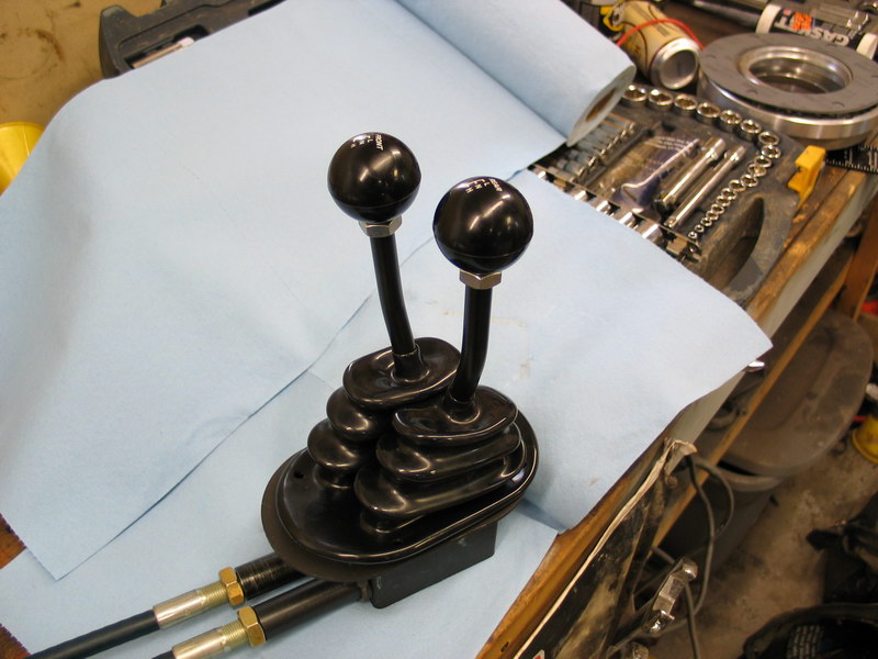 |
... and then the shift knobs. Looking at the shifter body from the end where the cables enter, the left stick shifts the front axle and the right stick shifts the rear axle. |
||||||||||||||||||||||||||||||||||||||||||||||||||||||||||||||||||||||||||||||||||||||||||||||||||||||||||||||||||||||||
Testing and Adjusting the Cable Shifters |
|||||||||||||||||||||||||||||||||||||||||||||||||||||||||||||||||||||||||||||||||||||||||||||||||||||||||||||||||||||||||
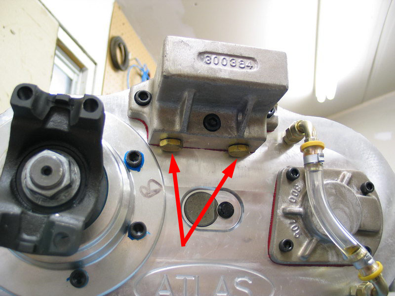 |
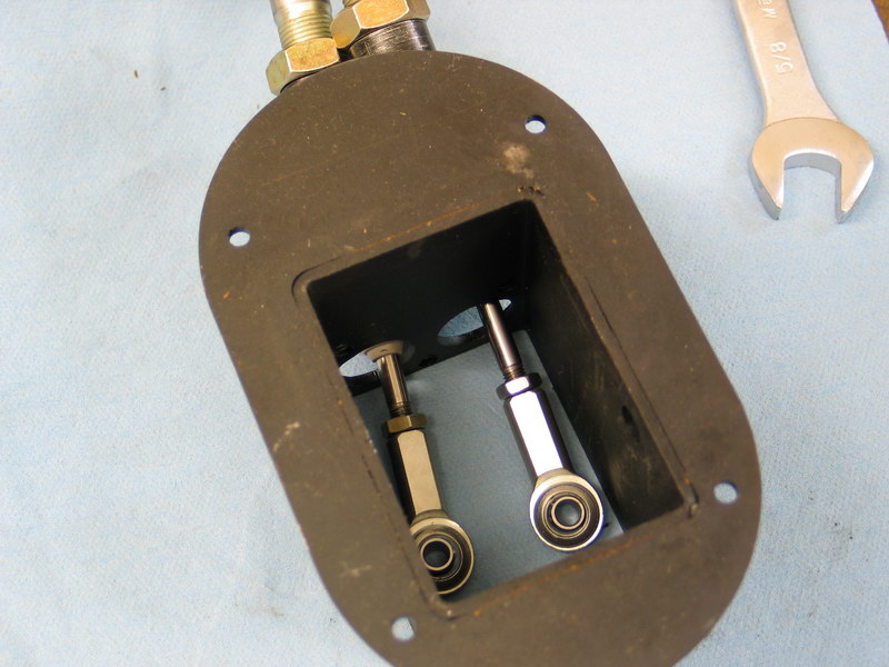
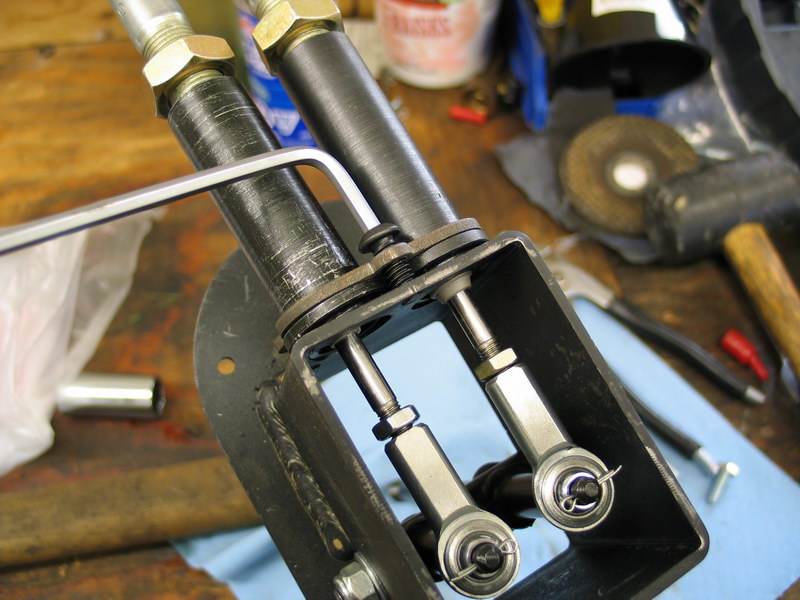
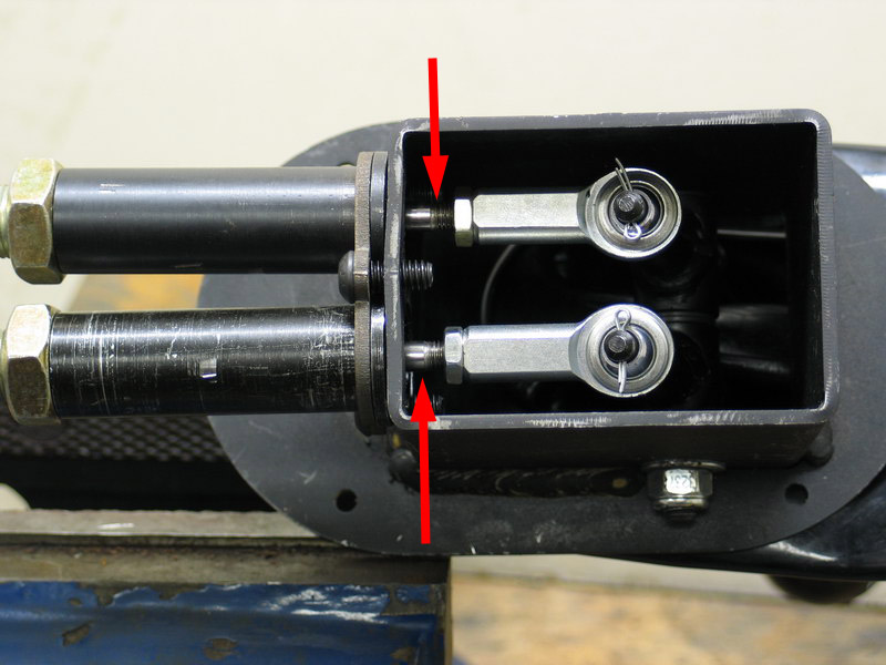
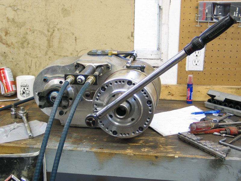
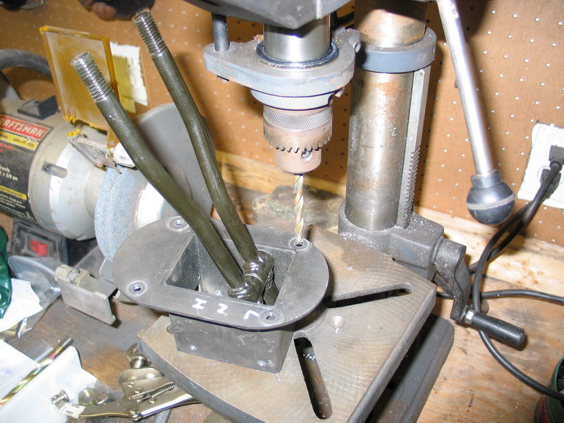
Before beginning the shift test and cable adjustment procedure, it's a good idea to back off the shift-rail detent set-screws a quarter turn. They are the large brass set-screws located on the underside of the back of the shift-rail housing - illustrated here by the red arrows. This will allow for easier initial shifting. As the Atlas is operated and breaks-in, the shift detent components will seat and the set-screws can be re-tightened to their original position. |
||||||||||||||||||||||||||||||||||||||||||||||||||||||||||||||||||||||||||||||||||||||||||||||||||||||||||||||||||||||||
| The next series of 3 pics illustrate the gear positions of the Atlas-4SP in terms of the position of the shift rails. The left rail (left and right relative to the vehicle when installed) is the rear axle and the right rail is the front axle. The pics are of the right (front axle) rail. The position of the shift rail is best illustrated by examining the position of the shift rail adapter (the black hexagonal part) in relation to the twin-stick base mount. | |||||||||||||||||||||||||||||||||||||||||||||||||||||||||||||||||||||||||||||||||||||||||||||||||||||||||||||||||||||||||
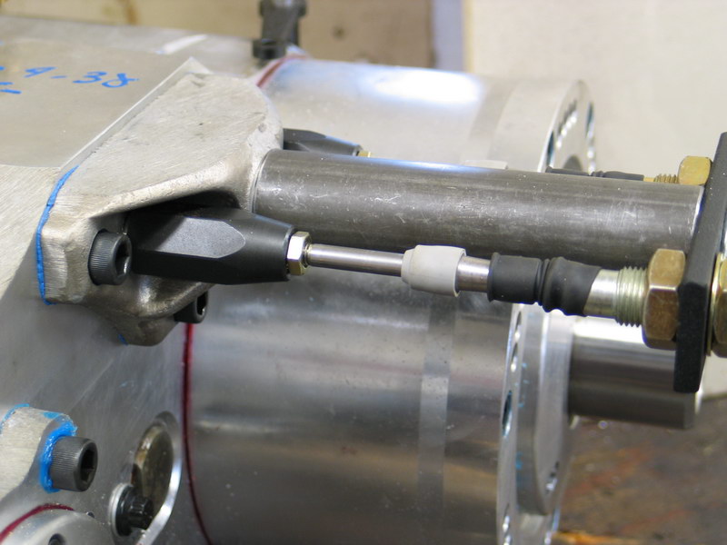 |
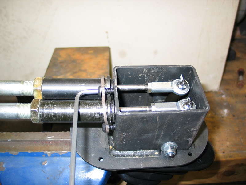
This is the "low-range" position. In this position the shift rail is retracted into the case, and there is virtually no gap between the shift rail adapter and the base mount. This correlates to a shifter-handle position of "away from the cables" Assuming the shift cables run in a straight line to the shifter body, this would correlate to the shift lever in the "front" or "forward" position. |
||||||||||||||||||||||||||||||||||||||||||||||||||||||||||||||||||||||||||||||||||||||||||||||||||||||||||||||||||||||||
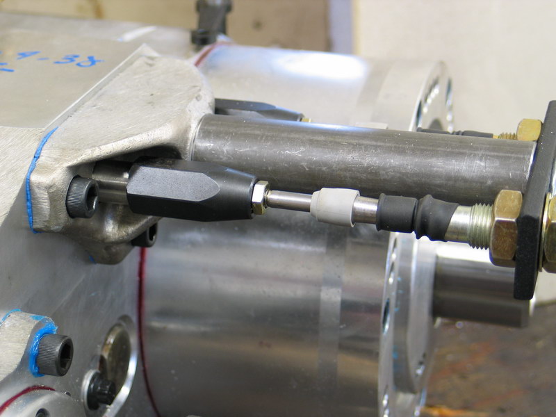 |
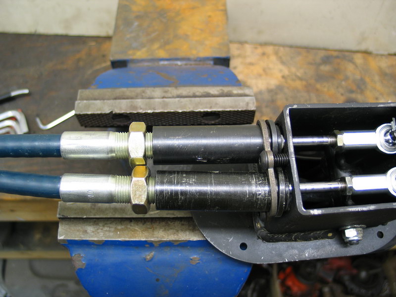
This is the "neutral" position. In this position the shift rail is extended mid-way out of the case, and there is a gap between the shift rail adapter and the base mount. About half an inch of shiny shift rail is visible between the shift rail adapter and the base mount. This correlates to a shifter-handle position of "in the middle of the throw" Assuming the shift cables run in a straight line to the shifter body, this would correlate to the shift lever in the "middle" position. |
||||||||||||||||||||||||||||||||||||||||||||||||||||||||||||||||||||||||||||||||||||||||||||||||||||||||||||||||||||||||
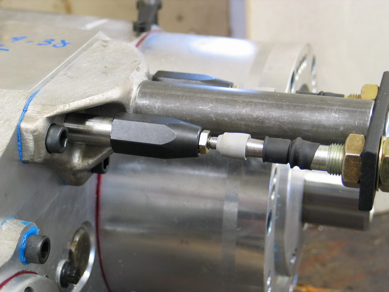 |
This is the "high-range" position. In this position the shift rail is extended all the way out of the case, and there is a bigger gap between the shift rail adapter and the base mount. About an inch of shiny shift rail is visible between the shift rail adapter and the base mount. This correlates to a shifter-handle position of "towards the cables" Assuming the shift cables run in a straight line to the shifter body, this would correlate to the shift lever in the "back" or "rear" position. |
||||||||||||||||||||||||||||||||||||||||||||||||||||||||||||||||||||||||||||||||||||||||||||||||||||||||||||||||||||||||
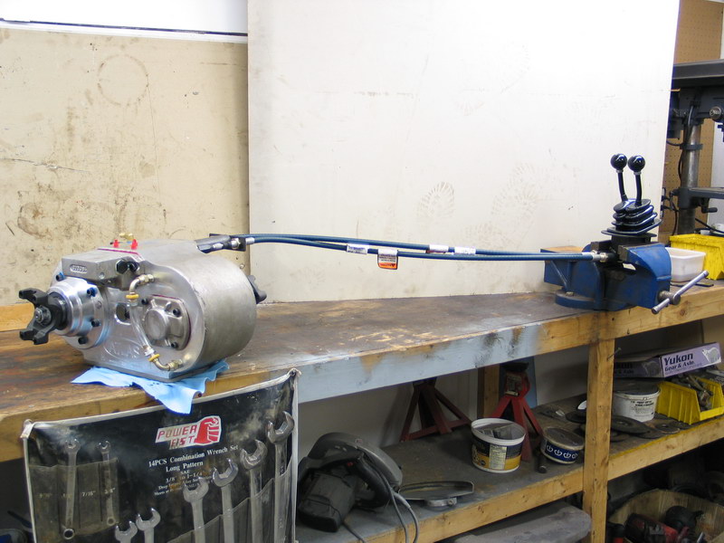 |
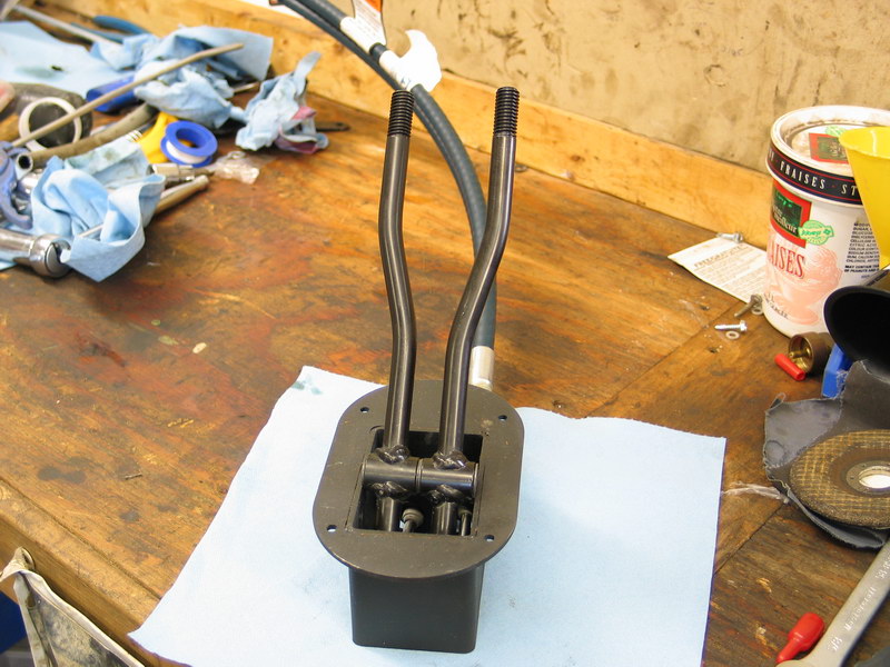
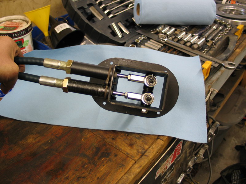
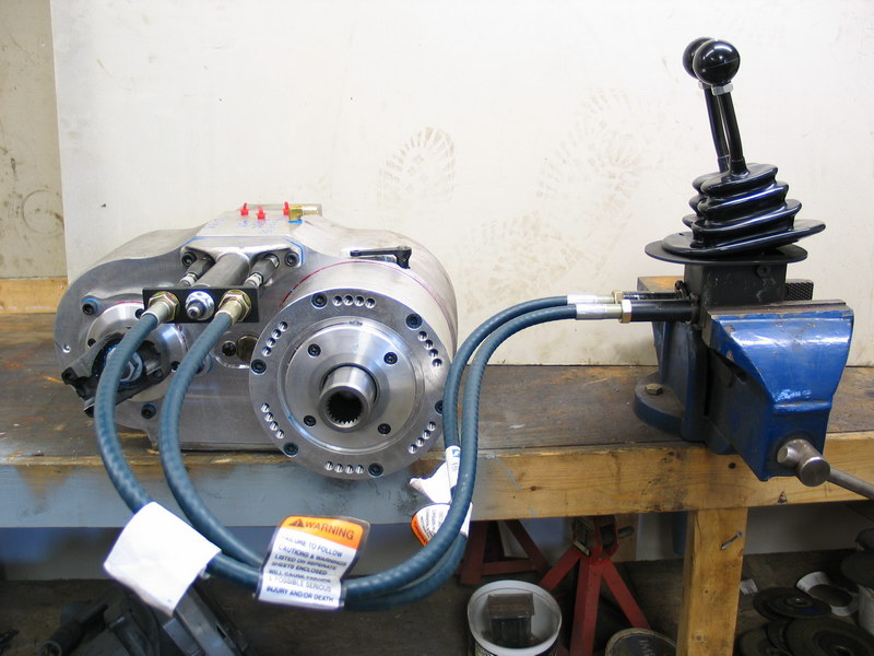
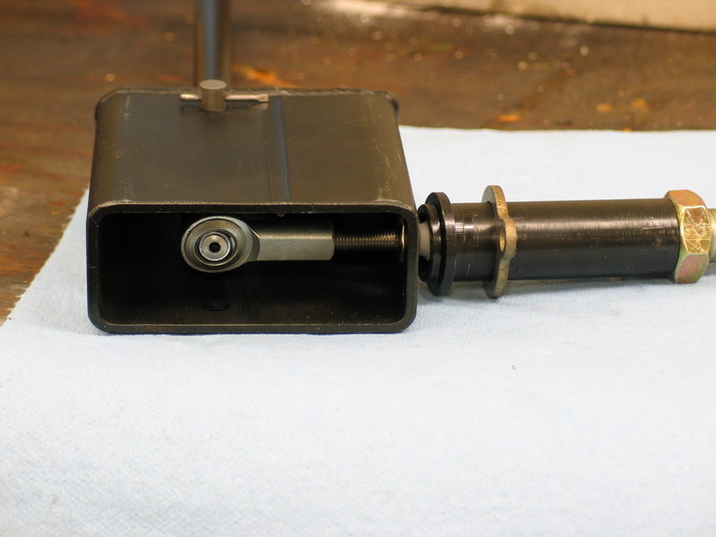
Now that we know what the shift positions are, we can set up the case and shifters on the bench to test and adjust the shifts. I set the case on the bench, stretched the cables out straight away from the case and clamped the shifter body in a vice so I could operate the shifters. |
||||||||||||||||||||||||||||||||||||||||||||||||||||||||||||||||||||||||||||||||||||||||||||||||||||||||||||||||||||||||
 |
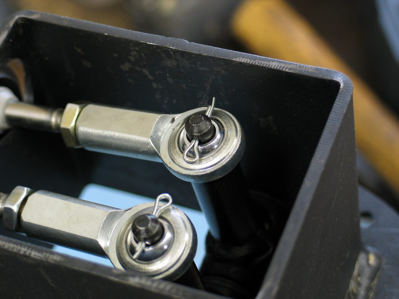
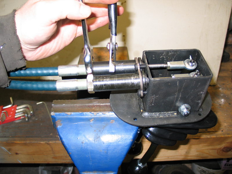
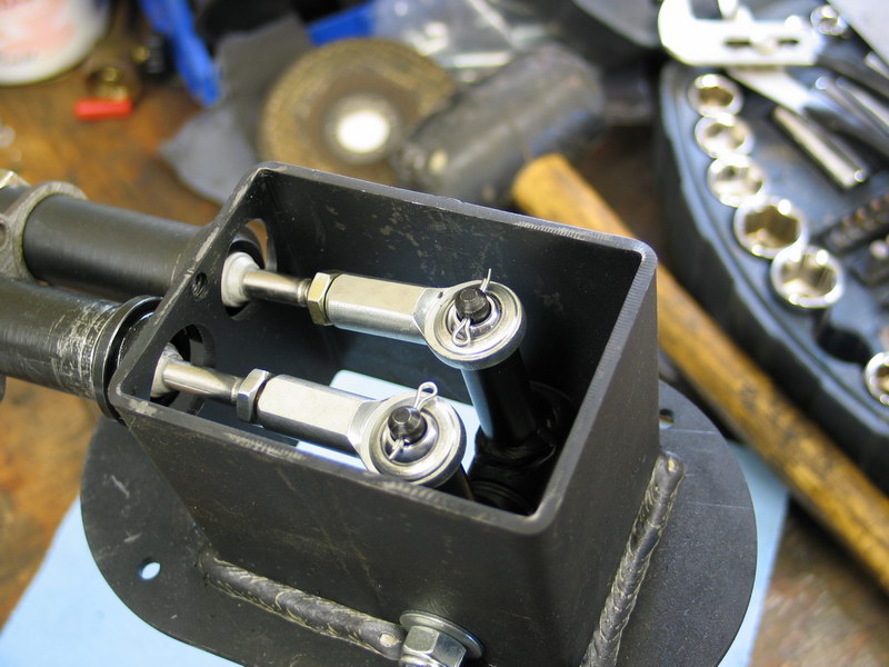
Essentially, what we want to check (and adjust to achieve if necessary) is that the throw of the shifters achieves a complete, positive shift, from L to N to H, without any interference between the Heim joints and the inside of the shifter body. Here we can see that on my initial setup (the jam nuts about halfway on the threads at both ends of the cables) the Heim joints contact the front of the shifter body when the levers are to the rear - i.e. when shifted to "High". The other possible condition would be that, with the shifters in the "Low" position, the little jam nuts on the cable rod would bottom on the shifter body. In extreme cases, there may be interference early enough in the shifters travel to actually prevent a complete shift. Regardless, the solution is to adjust the cables so that the shifter throw is limited only by the completion of the shift, with no interference inside the shifter body. |
||||||||||||||||||||||||||||||||||||||||||||||||||||||||||||||||||||||||||||||||||||||||||||||||||||||||||||||||||||||||
You can make adjustments either at the transfer case or at the shifter body - both achieve the same thing. Essentially, what you are adjusting is the relationship of the cable's sheath to the cable's inner rod (the rod that does the actual shifting) The adjustments you want to make are: If the Heims hit the front of the
shifter body / the case won't shift into High: If the Heims/jam nuts bottom on the
back inside of the shifter body / the case won't shift into Low: |
|||||||||||||||||||||||||||||||||||||||||||||||||||||||||||||||||||||||||||||||||||||||||||||||||||||||||||||||||||||||||
 |
At the transfer case end: To move the sheath towards the shifters use the same procedure except thread the outer jam nut towards the end of the cable (opposite to the direction indicated by the red arrow). |
||||||||||||||||||||||||||||||||||||||||||||||||||||||||||||||||||||||||||||||||||||||||||||||||||||||||||||||||||||||||
| Adjustment at the shifter end is only slightly more complicated. | |||||||||||||||||||||||||||||||||||||||||||||||||||||||||||||||||||||||||||||||||||||||||||||||||||||||||||||||||||||||||
 |
First loosen the button-head cap screws holding the barrel retainer plate to the shifter body. It is not necessary to remove them - just loosen them enough to allow the cable barrels to rotate in the barrel retainer plate. |
||||||||||||||||||||||||||||||||||||||||||||||||||||||||||||||||||||||||||||||||||||||||||||||||||||||||||||||||||||||||
 |
Hold the barrel with a pair of channel-lock pliers and loosen the lock nut. | ||||||||||||||||||||||||||||||||||||||||||||||||||||||||||||||||||||||||||||||||||||||||||||||||||||||||||||||||||||||||
 |
To move the sheath towards the case:
To move the sheath towards the shifters :
|
||||||||||||||||||||||||||||||||||||||||||||||||||||||||||||||||||||||||||||||||||||||||||||||||||||||||||||||||||||||||
| The following two pictures illustrate the results of my final adjustment. | |||||||||||||||||||||||||||||||||||||||||||||||||||||||||||||||||||||||||||||||||||||||||||||||||||||||||||||||||||||||||
 |
With the shifters in "Low", and the levers forward, there is plenty of clearance between jam nuts and shifter body, illustrated by the red arrows. | ||||||||||||||||||||||||||||||||||||||||||||||||||||||||||||||||||||||||||||||||||||||||||||||||||||||||||||||||||||||||
 |
With the shifters in "High", and the levers to the rear, there is plenty of clearance between the Heim joints and the shifter body, illustrated by the red arrows. Obviously, you want to have both cables, front and rear axles, adjusted approximately the same so the two levers are not way out of synch. |
||||||||||||||||||||||||||||||||||||||||||||||||||||||||||||||||||||||||||||||||||||||||||||||||||||||||||||||||||||||||
 |
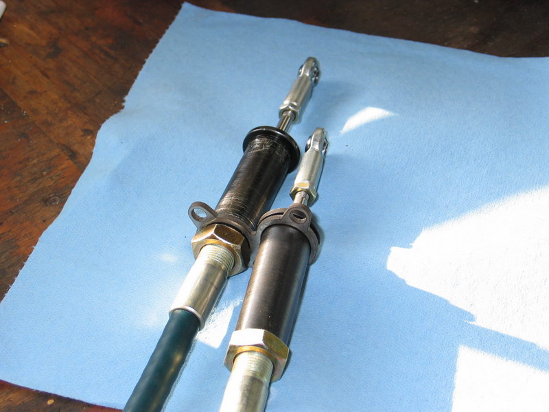
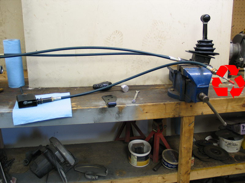
While I was adjusting the cables, I decided to test the minimum bend radius of the shift cables. That is - I wanted to see how tightly they could be bent and still deliver a nice, smooth, positive shift. I was pretty amazed at the results. |
||||||||||||||||||||||||||||||||||||||||||||||||||||||||||||||||||||||||||||||||||||||||||||||||||||||||||||||||||||||||
 |
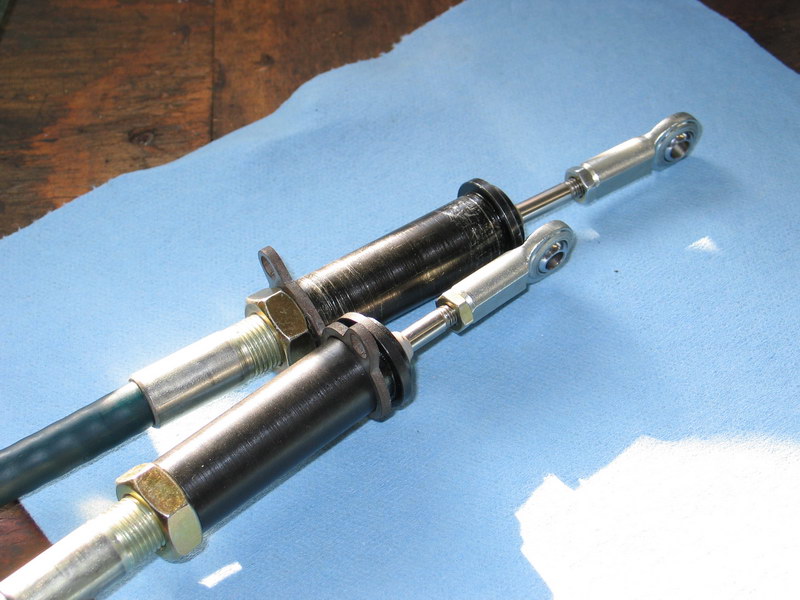
You can actually bend them in more than one plane and they still shift just as well as when they are straight. | ||||||||||||||||||||||||||||||||||||||||||||||||||||||||||||||||||||||||||||||||||||||||||||||||||||||||||||||||||||||||
 |
As long as you don't actually kink the cables you can achieve some pretty tight bend radii and the shift is still smooth and positive. I was really quite impressed with the results. |
||||||||||||||||||||||||||||||||||||||||||||||||||||||||||||||||||||||||||||||||||||||||||||||||||||||||||||||||||||||||
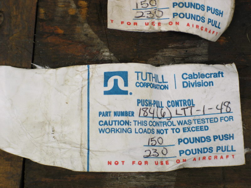 |
For interest's sake, here is the label from the cable. All three cables for the Atlas-4SP are the same part. | ||||||||||||||||||||||||||||||||||||||||||||||||||||||||||||||||||||||||||||||||||||||||||||||||||||||||||||||||||||||||
Preparing the Reduction Box Cable Shifter |
|||||||||||||||||||||||||||||||||||||||||||||||||||||||||||||||||||||||||||||||||||||||||||||||||||||||||||||||||||||||||
 |
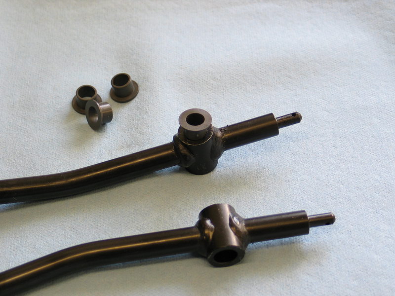
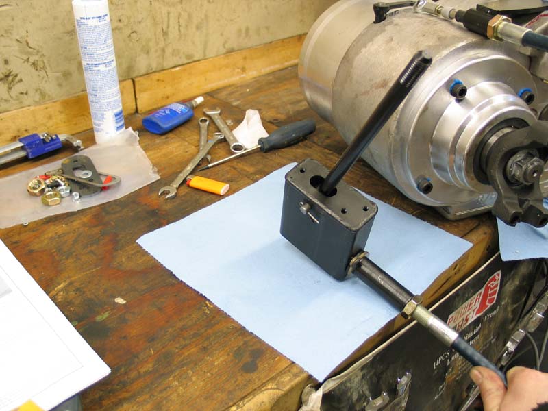
The last thing to do before test-fitting the case into the vehicle is to assemble and adjust/test the shifter for the reduction box. Begin by tapping the bushings (pn 340612) into the shifter handle (pn 340611) using a mallet. |
||||||||||||||||||||||||||||||||||||||||||||||||||||||||||||||||||||||||||||||||||||||||||||||||||||||||||||||||||||||||
 |
Thread the 1/4"-NF28 ball joint (pn 340613) into the handle and tighten. | ||||||||||||||||||||||||||||||||||||||||||||||||||||||||||||||||||||||||||||||||||||||||||||||||||||||||||||||||||||||||
 |
Slide the handle up through the bottom of the shifter housing (pn 340600). | ||||||||||||||||||||||||||||||||||||||||||||||||||||||||||||||||||||||||||||||||||||||||||||||||||||||||||||||||||||||||
 |
Align the handle's through-hole (with the bushings in it) with the top-most hole of the shifter housing, and insert the clevis pin (pn 340614)... | ||||||||||||||||||||||||||||||||||||||||||||||||||||||||||||||||||||||||||||||||||||||||||||||||||||||||||||||||||||||||
 |
...like this. | ||||||||||||||||||||||||||||||||||||||||||||||||||||||||||||||||||||||||||||||||||||||||||||||||||||||||||||||||||||||||
 |
Insert the cotter pin (pn 340616) through the clevis pin and spread the legs - unlike the twin-stick shifters you will not have to remove it later for installation into the vehicle. | ||||||||||||||||||||||||||||||||||||||||||||||||||||||||||||||||||||||||||||||||||||||||||||||||||||||||||||||||||||||||
 |
Slide the barrel retainer (pn 340610) over the cable barrel (pn 303305) like this. | ||||||||||||||||||||||||||||||||||||||||||||||||||||||||||||||||||||||||||||||||||||||||||||||||||||||||||||||||||||||||
 |
Remove the first jam nut and star washer from the cable and thread the remaining jam nut about halfway along the cable's threads, as shown. | ||||||||||||||||||||||||||||||||||||||||||||||||||||||||||||||||||||||||||||||||||||||||||||||||||||||||||||||||||||||||
 |
Thread the cable barrel onto the cable until it bottoms against the jam nut. | ||||||||||||||||||||||||||||||||||||||||||||||||||||||||||||||||||||||||||||||||||||||||||||||||||||||||||||||||||||||||
 |
Remove the red plastic dust cap from the end of the shift rod and thread the small 1/4"-NF28 jam nut completely on the rod. | ||||||||||||||||||||||||||||||||||||||||||||||||||||||||||||||||||||||||||||||||||||||||||||||||||||||||||||||||||||||||
 |
Insert the cable through the hole at the back of the shifter housing and thread the rod into the 1/4"-NF28 ball joint. | ||||||||||||||||||||||||||||||||||||||||||||||||||||||||||||||||||||||||||||||||||||||||||||||||||||||||||||||||||||||||
 |
By grasping the other end of the inner shift rod and turning (as shown), thread the shift rod completely into the 1/4"-NF28 ball joint. | ||||||||||||||||||||||||||||||||||||||||||||||||||||||||||||||||||||||||||||||||||||||||||||||||||||||||||||||||||||||||
 |
When the rod bottoms inside the ball joint, tighten the jam nut to lock it in place. Be sure to use a wrench to hold the body of the ball joint when tightening the jam nut to avoid placing undue stress on the socket of the ball joint. | ||||||||||||||||||||||||||||||||||||||||||||||||||||||||||||||||||||||||||||||||||||||||||||||||||||||||||||||||||||||||
 |
Seat the barrel against the shifter housing and secure in place with the barrel retainer, using the two 1/4"-NC20 x 5/8" button head cap screws (pn 340615). | ||||||||||||||||||||||||||||||||||||||||||||||||||||||||||||||||||||||||||||||||||||||||||||||||||||||||||||||||||||||||
 |
The completed shifter assembly should look like this. | ||||||||||||||||||||||||||||||||||||||||||||||||||||||||||||||||||||||||||||||||||||||||||||||||||||||||||||||||||||||||
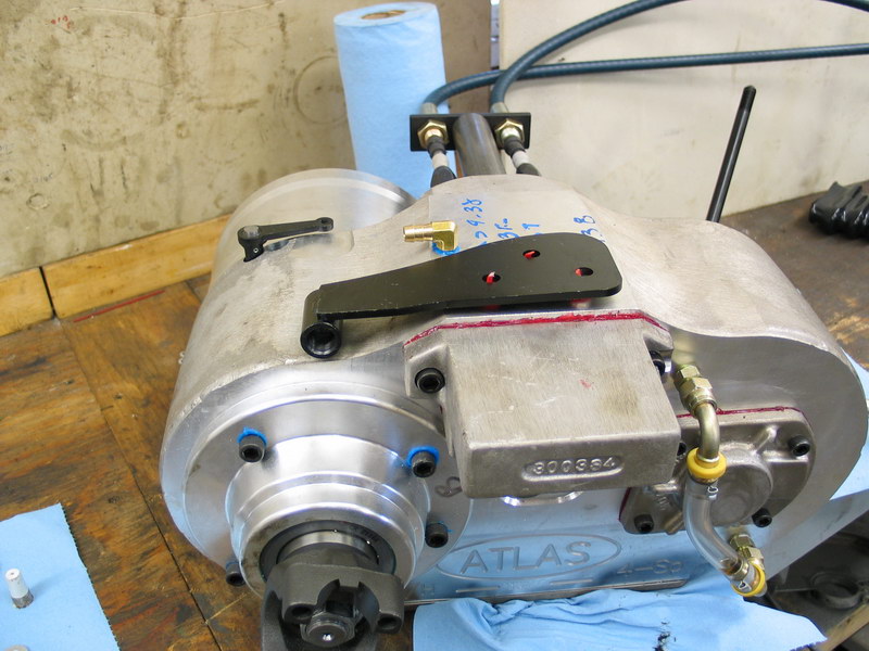 |
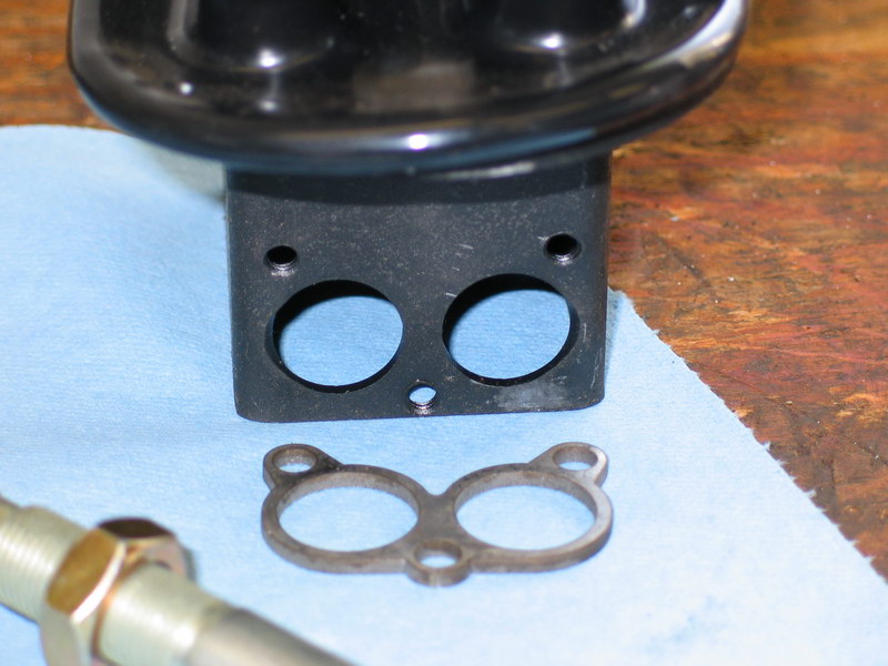
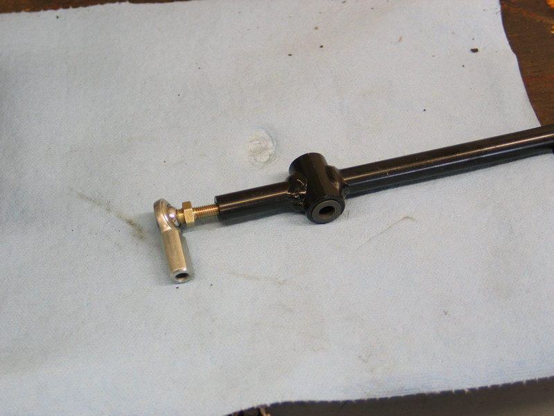
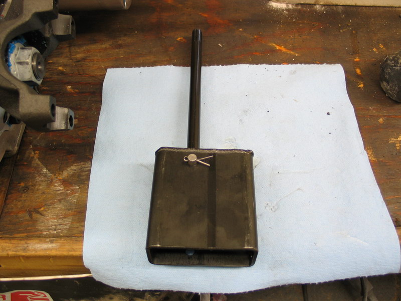
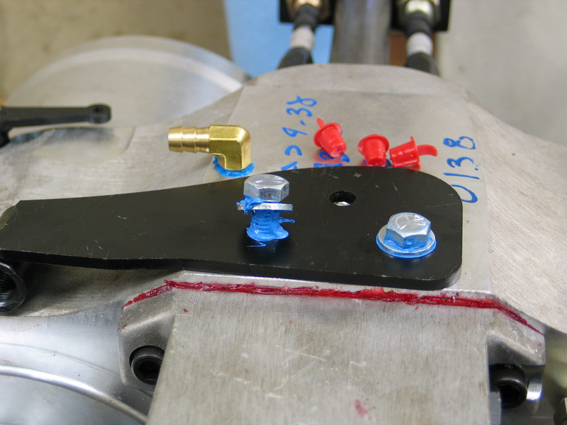
The next step is to connect the other end of the cable to the Atlas. This pic shows the placement and orientation of the cable shifter bracket (pn 340517-R). |
||||||||||||||||||||||||||||||||||||||||||||||||||||||||||||||||||||||||||||||||||||||||||||||||||||||||||||||||||||||||
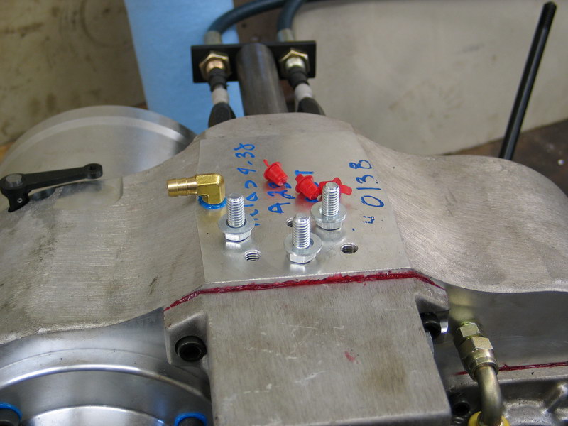 |
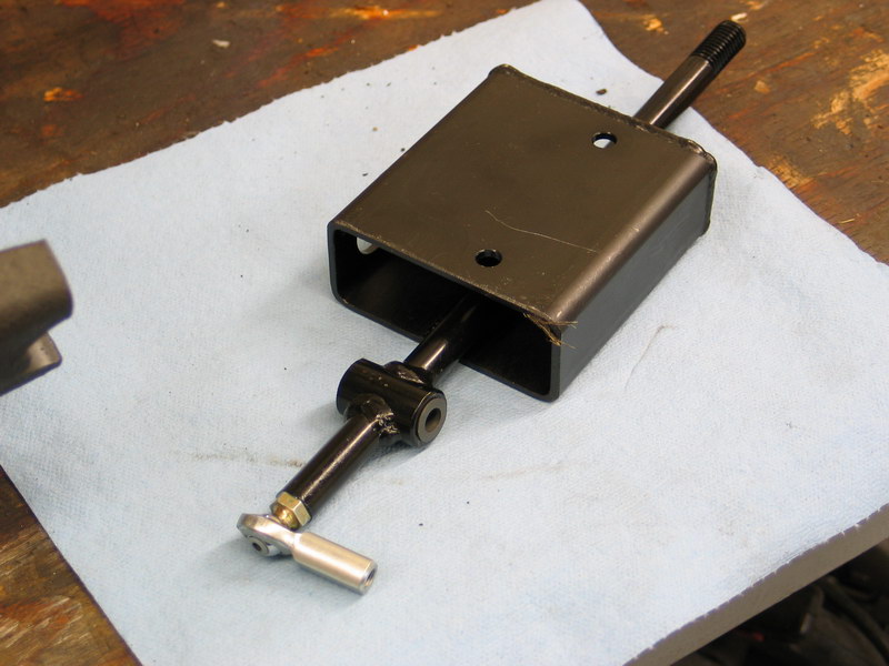
Remove the red plastic dust plugs from the three holes on the top of the case and prepare the three 3/8"-NC16 x 3/4" bracket mounting bolts (pn 723720) and flat washers (pn 720015). Place a dab of blue RTV on the threads of the bracket mounting bolts to seal them as they pass through into the case. |
||||||||||||||||||||||||||||||||||||||||||||||||||||||||||||||||||||||||||||||||||||||||||||||||||||||||||||||||||||||||
 |
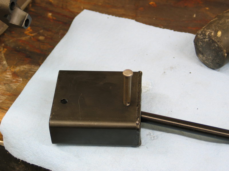
Fasten the bracket to the case with the three bolts. Torque the bolts to 15-18 ft/lbs. | ||||||||||||||||||||||||||||||||||||||||||||||||||||||||||||||||||||||||||||||||||||||||||||||||||||||||||||||||||||||||
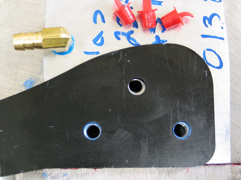 |
One of the very few problems I had during the project was the fact that the holes in the bracket didn't quite line up with the holes in the case, preventing all three bolts from being able to be installed. To remedy this I drilled out the misaligned hole in the bracket until I could insert and tighten all three bolts. |
||||||||||||||||||||||||||||||||||||||||||||||||||||||||||||||||||||||||||||||||||||||||||||||||||||||||||||||||||||||||
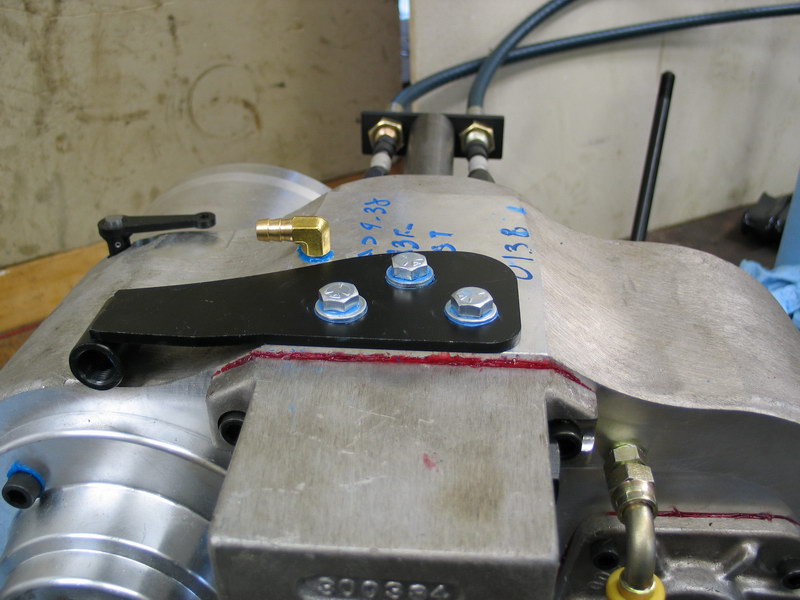 |
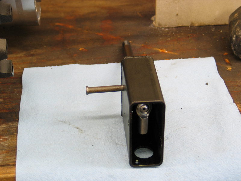
The installed bracket should look like this. | ||||||||||||||||||||||||||||||||||||||||||||||||||||||||||||||||||||||||||||||||||||||||||||||||||||||||||||||||||||||||
 |
Remove red plastic dust cap, the first jam nut, and the star washer from the free end of the cable. Thread the remaining jam nut about halfway along the cable's threads then thread the cable into the bracket by turning the whole shifter/cable assembly... |
||||||||||||||||||||||||||||||||||||||||||||||||||||||||||||||||||||||||||||||||||||||||||||||||||||||||||||||||||||||||
 |
... until the jam nut bottoms on the bracket. | ||||||||||||||||||||||||||||||||||||||||||||||||||||||||||||||||||||||||||||||||||||||||||||||||||||||||||||||||||||||||
 |
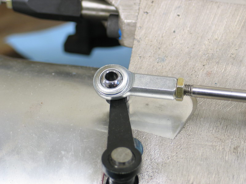
Thread the 1/4"-NF28 female Heim joint (pn 303313) completely onto the shift rod until it bottoms out. Align the Heim joint so that the bore in the spherical bearing is centered in the race and vertical, then hold the Heim joint in place with a wrench and tighten the jam nut. |
||||||||||||||||||||||||||||||||||||||||||||||||||||||||||||||||||||||||||||||||||||||||||||||||||||||||||||||||||||||||
 |
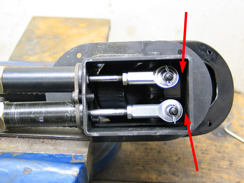
Hold the shifter housing upright and move the stick through its full range of motion. Check that there is no interference between the stick and the housing where the stick passes through the oval slot (red arrows) and ... |
||||||||||||||||||||||||||||||||||||||||||||||||||||||||||||||||||||||||||||||||||||||||||||||||||||||||||||||||||||||||
 |
... that there is no interference between the ball joint and the inside of the shifter housing. If there is any interference, loosen the button head cap screws and the large jam nut on the cable. Rotate the barrel independently to adjust the shift handle / ball joint position. Recheck for interference and continue adjusting the barrel as necessary. Once you are satisfied with the adjustment, securely re-tighten the jam nut and button head cap screws. |
||||||||||||||||||||||||||||||||||||||||||||||||||||||||||||||||||||||||||||||||||||||||||||||||||||||||||||||||||||||||
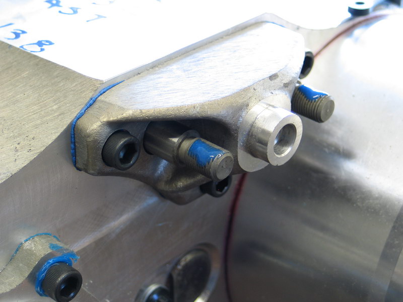
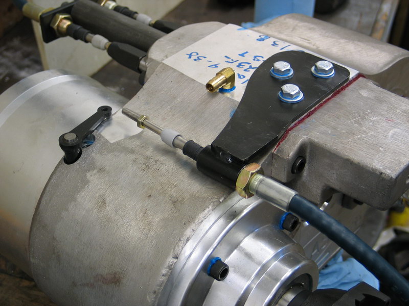
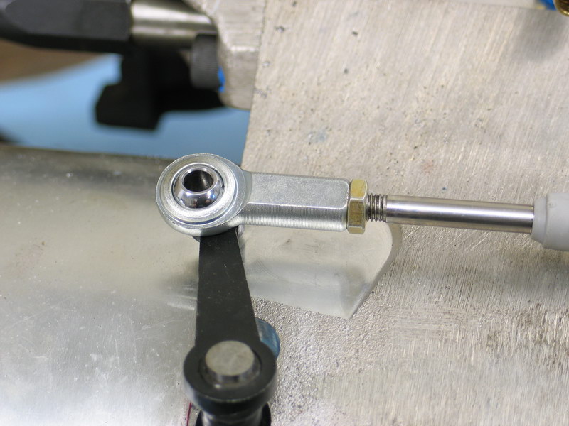
| It is now time to adjust the reduction box shift cable at the transfer case end to ensure that the range of motion of the pivot lever (the mechanical arm on the case that shifts the reduction box) falls entirely within the range of motion of the cable. | |||||||||||||||||||||||||||||||||||||||||||||||||||||||||||||||||||||||||||||||||||||||||||||||||||||||||||||||||||||||||
 |
Recall that when the shifter is aft (back towards the cable) this is the Low Range position and when it is fwd (away from the cable) it is in the High Range position. In this pic the shifter is in Low Range position. |
||||||||||||||||||||||||||||||||||||||||||||||||||||||||||||||||||||||||||||||||||||||||||||||||||||||||||||||||||||||||
 |
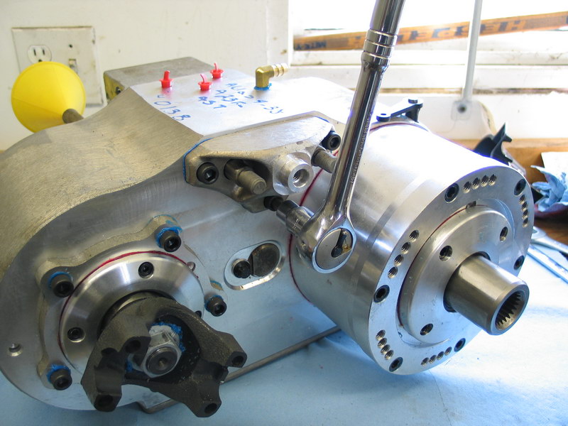
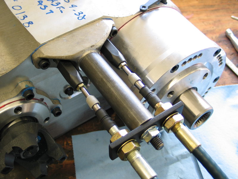
The pivot lever on the case, just behind the planetary reduction box, moves fore and aft to mechanically shift the reduction box. When it is aft (towards the back of the transfer case) the reduction box is in Low Range - as in this pic. |
||||||||||||||||||||||||||||||||||||||||||||||||||||||||||||||||||||||||||||||||||||||||||||||||||||||||||||||||||||||||
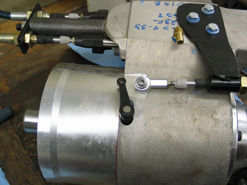 |
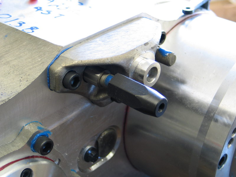
When it is forward (towards the front of the transfer case) the reduction box is in High Range - as in this pic. | ||||||||||||||||||||||||||||||||||||||||||||||||||||||||||||||||||||||||||||||||||||||||||||||||||||||||||||||||||||||||
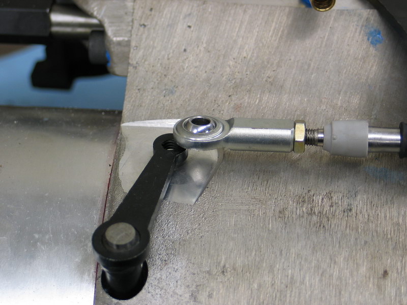 |
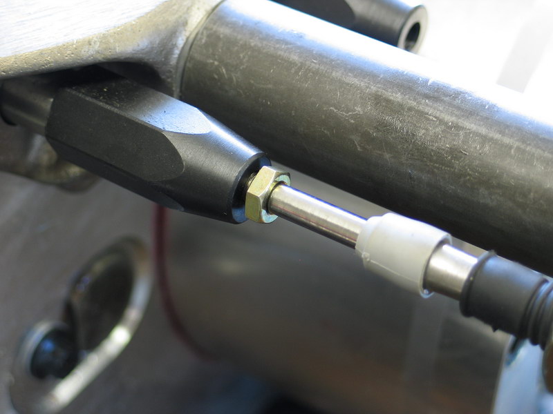
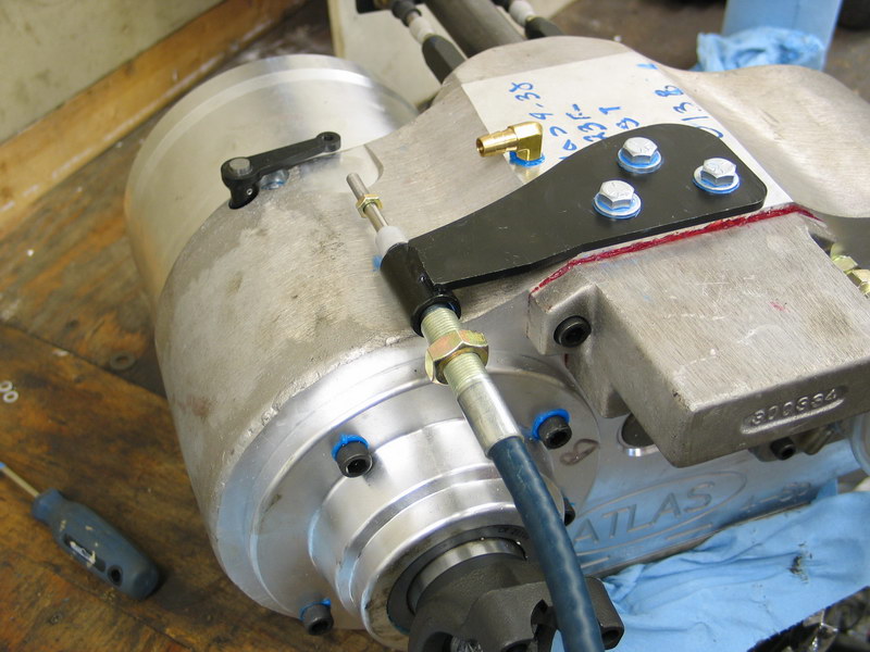
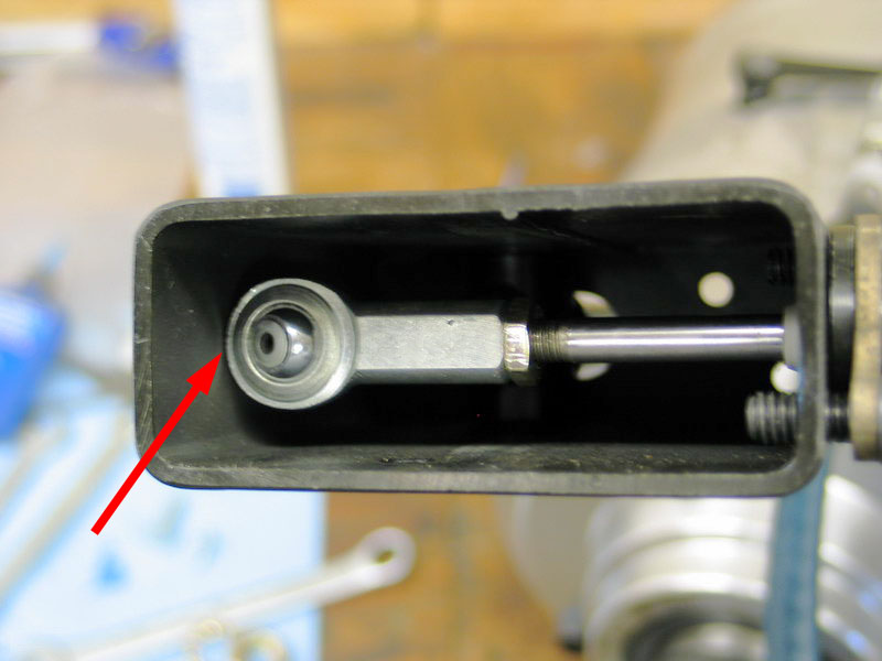
To begin the adjustment, place the shifter in Low Range and move the pivot lever to the Low Range position. Adjust the cable so that the bore in the Heim joint is behind (more to the rear of the case than) the tapped hole in the pivot lever by threading the cable/shifter assembly into or out of the cable shifter bracket. | ||||||||||||||||||||||||||||||||||||||||||||||||||||||||||||||||||||||||||||||||||||||||||||||||||||||||||||||||||||||||
 |
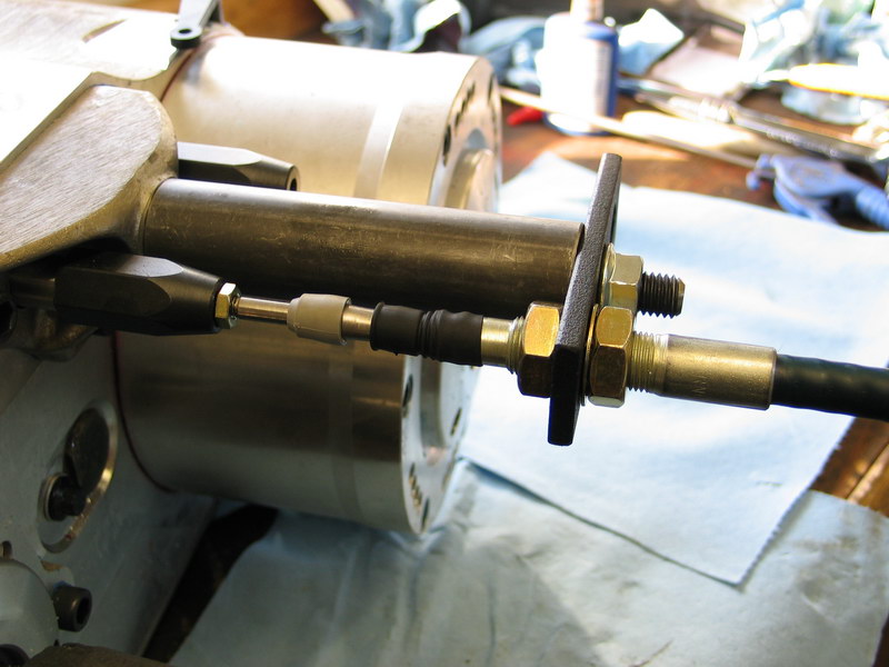
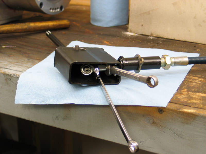
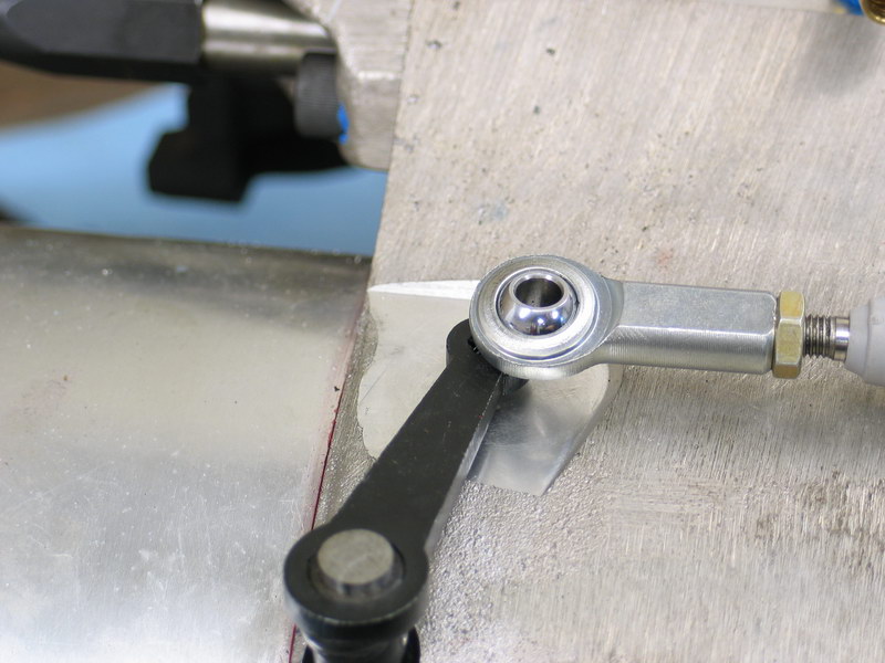
Move the shifter and the pivot lever to the High Range position. Check that bore in the Heim joint is forward of the tapped hole in the pivot lever. In this picture you can see that it is not, and so further adjustment is required. Adjust the cable so that the bore in the Heim joint is forward of the tapped hole in the pivot lever by threading the cable/shifter assembly into or out of the cable shifter bracket, as before. |
||||||||||||||||||||||||||||||||||||||||||||||||||||||||||||||||||||||||||||||||||||||||||||||||||||||||||||||||||||||||
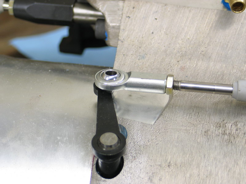
 |
In this pic I have threaded the cable into the bracket to move the Heim joint ahead. It is now slightly forward of the tapped hole in the pivot lever as it should be. | ||||||||||||||||||||||||||||||||||||||||||||||||||||||||||||||||||||||||||||||||||||||||||||||||||||||||||||||||||||||||
 |
Move the shifter and the pivot lever back to the Low Range position and double-check that, in Low Range, the Heim joint is still behind the tapped hole in the pivot lever. In this case it is, so adjustment is complete. If it is not, you will have to continue to fine tune the adjustment by threading the cable/shifter assembly into or out of the cable shifter bracket until the pivot lever travel is centered within the cable travel. |
||||||||||||||||||||||||||||||||||||||||||||||||||||||||||||||||||||||||||||||||||||||||||||||||||||||||||||||||||||||||
 |
Final adjustment position - High Range. | ||||||||||||||||||||||||||||||||||||||||||||||||||||||||||||||||||||||||||||||||||||||||||||||||||||||||||||||||||||||||
 |
Final adjustment position - Low Range. | ||||||||||||||||||||||||||||||||||||||||||||||||||||||||||||||||||||||||||||||||||||||||||||||||||||||||||||||||||||||||
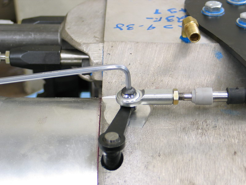 |
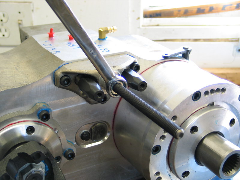
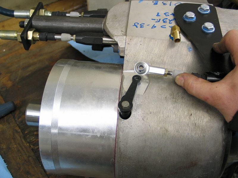
Attach the Heim joint to the pivot lever using the 1/4"-NC20 x 5/8" button head cap screw (pn 340615). | ||||||||||||||||||||||||||||||||||||||||||||||||||||||||||||||||||||||||||||||||||||||||||||||||||||||||||||||||||||||||
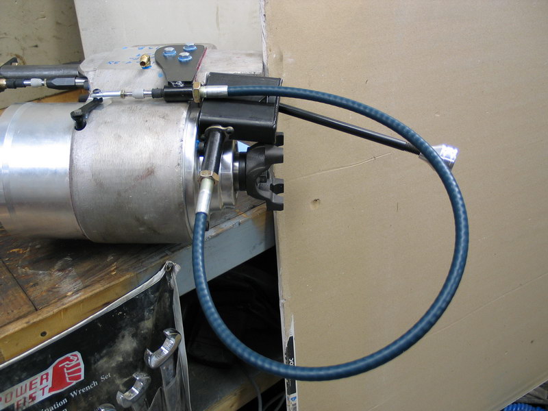 |
The reduction box cable shifter is capable of the same impressive bend radii as the twin-stick shifters while still providing a solid shift. | ||||||||||||||||||||||||||||||||||||||||||||||||||||||||||||||||||||||||||||||||||||||||||||||||||||||||||||||||||||||||
Installing the Adapter-Spacer RingIn my installation, the final step before test-fitting the Atlas into the vehicle was to install the adapter spacer. This was required to ensure the 10 x 23 SM465 to Atlas spud shaft does not bottom inside the Atlas input. As it turns out, because of the part I used as the spacer, I also gained several clocking angles (a clocking angle is the rotation at which the transfer case is installed - i.e. how much below the input the front output hangs). |
|||||||||||||||||||||||||||||||||||||||||||||||||||||||||||||||||||||||||||||||||||||||||||||||||||||||||||||||||||||||||
|
The front of the Atlas-4SP's reduction box is equipped with four different spacings of the 6-bolt round pattern. This alone would offer you four different clocking angles, however many Advance Adapters' adapters will also have more than one bolt pattern, meaning that eight clocking options are often available. Typical clocking options might be: Left drop case: 7, 14, 17, 21, 24, 28, 31, or 38 degrees. Right drop case: 4, 11, 14, 18, 21, 25, 28, or 35 degrees. |
||||||||||||||||||||||||||||||||||||||||||||||||||||||||||||||||||||||||||||||||||||||||||||||||||||||||||||||||||||||||
|
In my application, because the adapter spacer itself has five different spacings, and it can be bolted to any of the four spacings on the Atlas I have a "theoretical" total of 5x4= 20 different clocking options. In reality, not every combination ends up being different, in fact, many are the same but at the very least I had 5 or 10 different options. In my case I wanted the case to be clocked fairly flat for clearance, but without causing too many clearance problems with frame, floor, etc. The next section details test-fitting the case at different clocking angles and selecting the best fit. The many different transmission and adapter combinations that can be used with the Atlas-4SP mean that there are far too many possibilities to cover here - the best bet is to do some research in the Atlas Transfer Case Installation Guide which details many combinations and options, and then talk to one of the techs at Advance. |
||||||||||||||||||||||||||||||||||||||||||||||||||||||||||||||||||||||||||||||||||||||||||||||||||||||||||||||||||||||||
 |
If you're using a spacer adapter like I did, first install one of the 6-bolt round gaskets on the face of the reduction box. | ||||||||||||||||||||||||||||||||||||||||||||||||||||||||||||||||||||||||||||||||||||||||||||||||||||||||||||||||||||||||
 |
Fit the spacer adapter in place and install with the six socket-head cap screws. | ||||||||||||||||||||||||||||||||||||||||||||||||||||||||||||||||||||||||||||||||||||||||||||||||||||||||||||||||||||||||
 |
Torque them to 28-30 ft/lbs. | ||||||||||||||||||||||||||||||||||||||||||||||||||||||||||||||||||||||||||||||||||||||||||||||||||||||||||||||||||||||||
The Atlas-4SP is now assembled, lubed, and ready for test-fitting into the vehicle. Test-fitting the Atlas-4SP and Clocking Options In this phase we will install the case temporarily in place, experiment with various clocking angles and check clearances. |
|||||||||||||||||||||||||||||||||||||||||||||||||||||||||||||||||||||||||||||||||||||||||||||||||||||||||||||||||||||||||
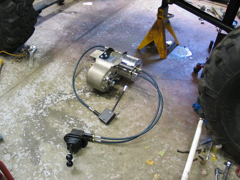 |
Here's the completely assembled unit ready for installation. | ||||||||||||||||||||||||||||||||||||||||||||||||||||||||||||||||||||||||||||||||||||||||||||||||||||||||||||||||||||||||
|
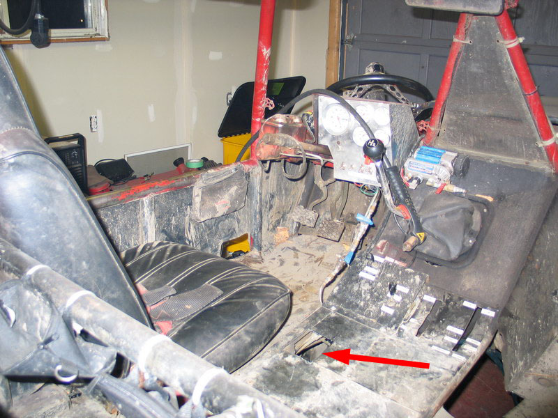
And here is the tunnel where it will be installed. Before you hoist it into place it's a good idea to spend some time with the tape measure doing some preliminary clearance checks - once you get it up into place and ready to slide onto the splines it's pretty heavy and a little cumbersome and that's not the time to find out the exhaust is in the way. Remove any offending components, place the transmission in neutral, and fit the case onto the adapter. The use of a proper transmission jack is highly recommended. I have intentionally omitted pictures of my old-drywall-compound-pail-couple-of-4x4s-and-wobbly-floor-jack method! |
||||||||||||||||||||||||||||||||||||||||||||||||||||||||||||||||||||||||||||||||||||||||||||||||||||||||||||||||||||||||
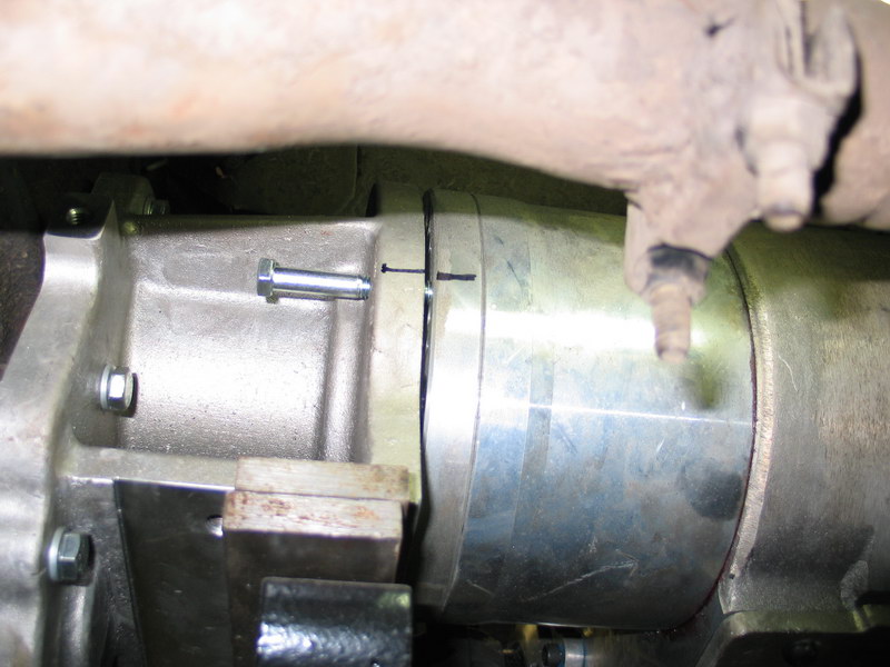 |
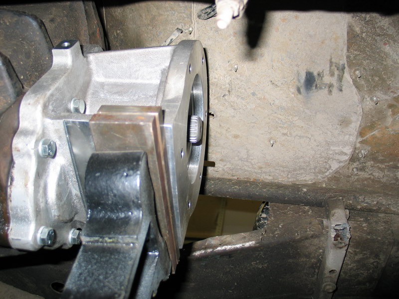
With the case in place, leave a tiny gap between the face of the adapter and the mounting face of the case so that you can just see the bolt holes in the mounting face of the case. Tilt / rotate the case around the input shaft while fishing a bolt through from the front of the adapter, through one of the mounting holes in the adapter, until you get it engaged in one of the threaded holes in the case. |
||||||||||||||||||||||||||||||||||||||||||||||||||||||||||||||||||||||||||||||||||||||||||||||||||||||||||||||||||||||||
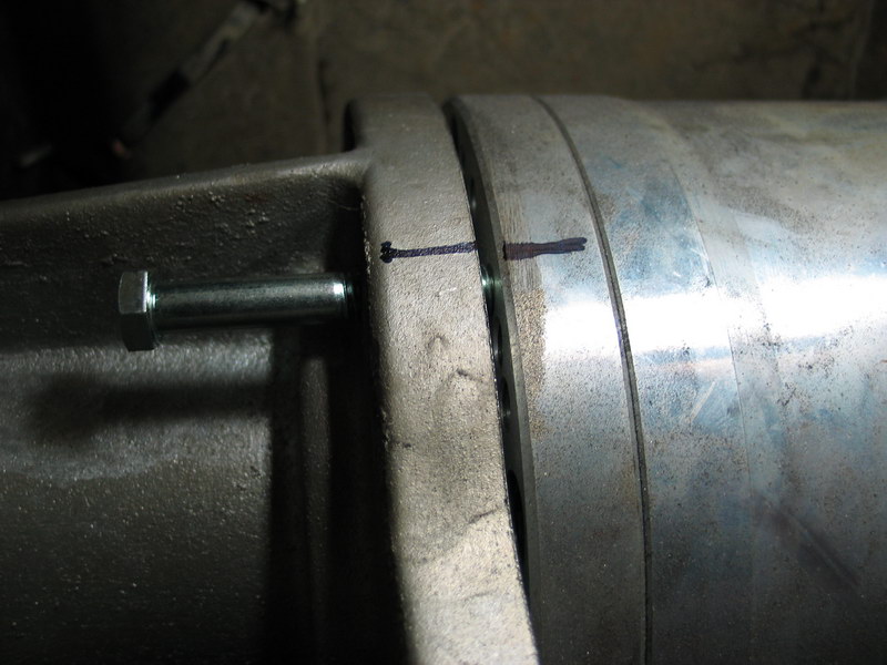 |
Mark this position on both the adapter and the case (as shown by the black marker lines in pic at left) - this you can now use as an alignment reference mark. | ||||||||||||||||||||||||||||||||||||||||||||||||||||||||||||||||||||||||||||||||||||||||||||||||||||||||||||||||||||||||
 |
Slightly different view of the process. | ||||||||||||||||||||||||||||||||||||||||||||||||||||||||||||||||||||||||||||||||||||||||||||||||||||||||||||||||||||||||
 |
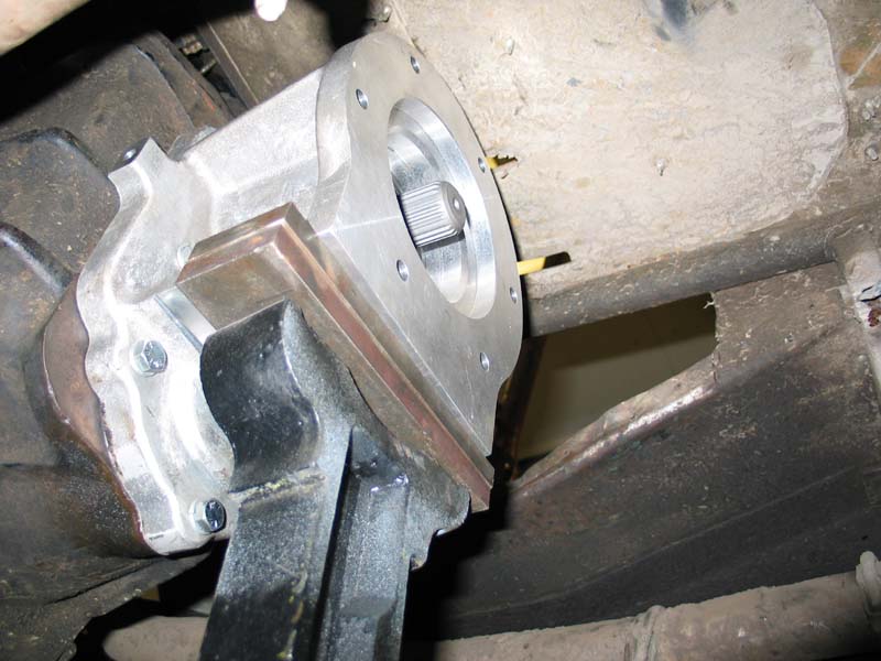
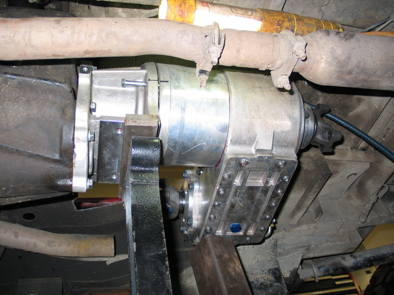
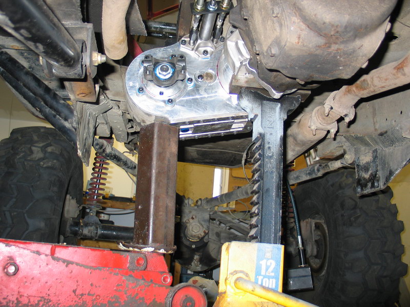
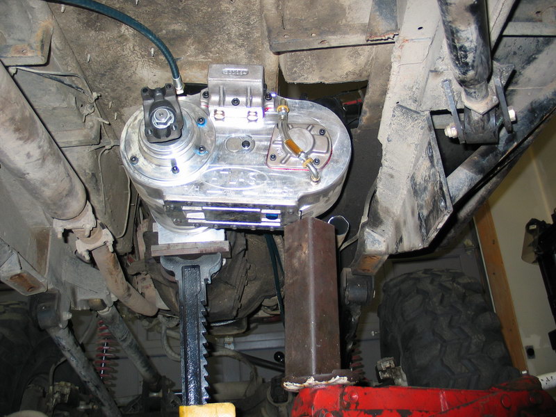
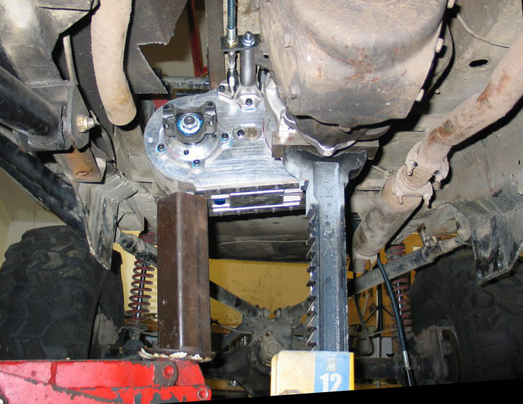
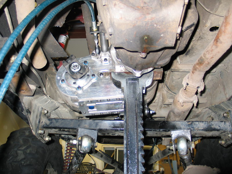
You can now rotate the case to different "clocking angles' and check for clearances etc. in order to determine your preferred clocking angle. I used a floor jack and piece of square tube to support the right side of the case in different positions as I checked. This is the view from the rear with the case clocked at 11°. |
||||||||||||||||||||||||||||||||||||||||||||||||||||||||||||||||||||||||||||||||||||||||||||||||||||||||||||||||||||||||
 |
View from the front at 11°. At 11° I measured 28-7/16” clearance between the floor and the lowest part of the case. |
||||||||||||||||||||||||||||||||||||||||||||||||||||||||||||||||||||||||||||||||||||||||||||||||||||||||||||||||||||||||
 |
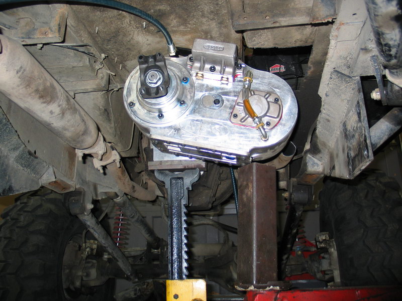
The next hole in the pattern on the front of the case allowed me to clock the case to 5°. This is the view from the rear at 5°. |
||||||||||||||||||||||||||||||||||||||||||||||||||||||||||||||||||||||||||||||||||||||||||||||||||||||||||||||||||||||||
 |
View from the front at 5°. At 5° I measured 29-7/16” clearance between the floor and the lowest part of the case. In other words, I gained a whole inch of clearance. It was a tighter fit at 5° than at 11° (in the pic at left you can see where I had to cut the exhaust) but I settled on 5° for the improved ground clearance. |
||||||||||||||||||||||||||||||||||||||||||||||||||||||||||||||||||||||||||||||||||||||||||||||||||||||||||||||||||||||||
 |
Side view at 5°. You can see the alignment marks I made at both 5° and 11°. | ||||||||||||||||||||||||||||||||||||||||||||||||||||||||||||||||||||||||||||||||||||||||||||||||||||||||||||||||||||||||
Installing the Atlas-4SPOnce you have your desired clocking angle figured out and marked, it's time to remove the case and prep it for final installation into the vehicle. |
|||||||||||||||||||||||||||||||||||||||||||||||||||||||||||||||||||||||||||||||||||||||||||||||||||||||||||||||||||||||||
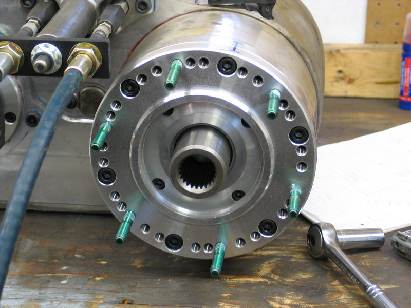 |
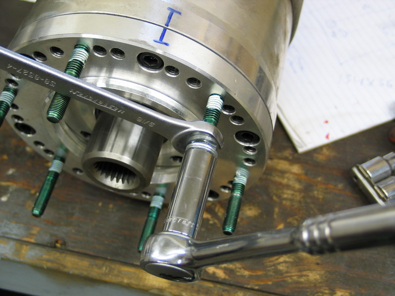
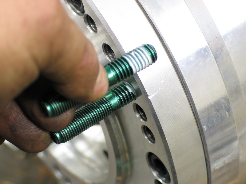
Using the alignment marks made during the test-fitting procedure, install the six Atlas Mounting Studs (pn 302069) finger tight into the mounting face of the Atlas / Adapter Spacer (as applicable). Thread in each one, inserting the end that has the pre-applied thread locking compound. Make sure you get each one in the correct position relative to its neighbors (i.e. that there are the same number of holes between each pair). You can always slip on the gasket to check before tightening them. |
||||||||||||||||||||||||||||||||||||||||||||||||||||||||||||||||||||||||||||||||||||||||||||||||||||||||||||||||||||||||
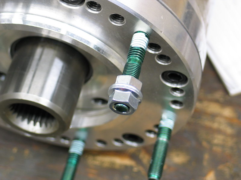 |
The studs are a special tapered-fit aluminum design and so must be installed carefully and tightened securely without over tightening. Getting them properly seated and tightened is a bit of a trick. The procedure I used is as follows: First I threaded on two nuts back-to-back... |
||||||||||||||||||||||||||||||||||||||||||||||||||||||||||||||||||||||||||||||||||||||||||||||||||||||||||||||||||||||||
 |
Then with a wrench on the inner nut to keep the outer nut from turning I used a socket on the outer nut to turn the stud into its hole. It's a bit tricky as you have to hold the inner nut fast against the outer while rotating the whole assembly together but you will soon get the hang of it. |
||||||||||||||||||||||||||||||||||||||||||||||||||||||||||||||||||||||||||||||||||||||||||||||||||||||||||||||||||||||||
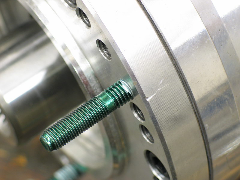 |
Without a depth gauge, spec, or torque measurement given, and the instruction manual providing only a caution to "not over-seat the studs into the front of the case." it was a matter of professional estimation (aka wild-ass guess) as to how deep to install the studs. I chose to tighten them just to the end of the thread locker as shown. | ||||||||||||||||||||||||||||||||||||||||||||||||||||||||||||||||||||||||||||||||||||||||||||||||||||||||||||||||||||||||
 |
This pic shows an approximation of how deep they are seated when so installed. | ||||||||||||||||||||||||||||||||||||||||||||||||||||||||||||||||||||||||||||||||||||||||||||||||||||||||||||||||||||||||
 |
Install the case into the vehicle, sliding the input over the splines of the output shaft and inserting the six mounting studs through their holes on the adapter. Apply pressure from the rear of the case until the mating face of the adapter and case are together with no gap. Do not use the fasteners to draw the components together - if they do not readily mate without a gap, disassemble and investigate the cause of any interference. Make particularly sure that the transmission output shaft / stub shaft is not bottoming inside the Atlas input. |
||||||||||||||||||||||||||||||||||||||||||||||||||||||||||||||||||||||||||||||||||||||||||||||||||||||||||||||||||||||||
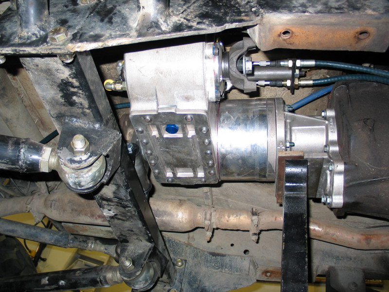 |
With everything in place, and using a little Loctite thread locker, install the nuts on each of the studs and tighten to 26-28 ft/lbs. | ||||||||||||||||||||||||||||||||||||||||||||||||||||||||||||||||||||||||||||||||||||||||||||||||||||||||||||||||||||||||
 |
With the Atlas securely in place at your chosen rotation, it's time to mark the correct oil level on the sight tube. I first drew a line with a permanent marker, and then attached a small zip tie to mark the level of the oil within the sight tube. |
||||||||||||||||||||||||||||||||||||||||||||||||||||||||||||||||||||||||||||||||||||||||||||||||||||||||||||||||||||||||
Installing the Cable Shifters in the Vehicle |
|||||||||||||||||||||||||||||||||||||||||||||||||||||||||||||||||||||||||||||||||||||||||||||||||||||||||||||||||||||||||
 |
With the case in place, it's time to install the shifters. The single-stick shifter for the reduction box installs from under the rig and so can remain attached to its cable. On the other hand, the twin-stick assembly is installed down through the floor and so must be removed from the cables for installation. Pull the cotter pins (remember I said not to spread the legs earlier!) and slip the Heim joints off the shifters, then remove the cap screws securing the barrel retainer plate to the shifter body. Remove the cables from the shifter body and keep the cotter pins and cap screws handy. |
||||||||||||||||||||||||||||||||||||||||||||||||||||||||||||||||||||||||||||||||||||||||||||||||||||||||||||||||||||||||
 |
The instructions state that the shifter body bottom cover plate (pn 303302) is to be secured to the shifter body using the four small #10 x 1/2" self-drilling screws (pn 722542). Since I knew the shifter body would be installed in tight quarters up under the rig where it would be difficult to get to with a drill, I pre-drilled the holes in the shifter body to match the bottom cover plate. This way I would be able to install the self-drilling screws with a small 1/4" ratchet and socket. |
||||||||||||||||||||||||||||||||||||||||||||||||||||||||||||||||||||||||||||||||||||||||||||||||||||||||||||||||||||||||
 |
Before installation I drilled out the mounting holes in the shifter body to accept a 1/4" bolt. This required that I first remove the shift knobs, jam nuts, and twin-stick shift boot. |
||||||||||||||||||||||||||||||||||||||||||||||||||||||||||||||||||||||||||||||||||||||||||||||||||||||||||||||||||||||||
 |
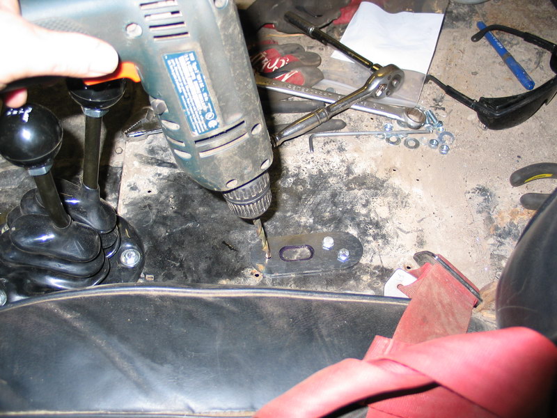
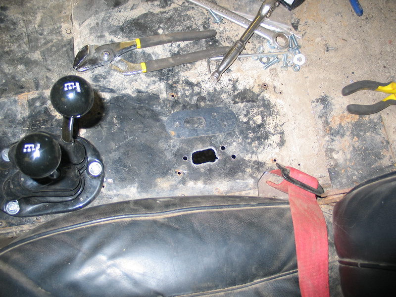
Using the bottom of the shifter body as a template, make a rectangular cutout in the floor where you want the shifters located. When you choose the location, make sure you have clearance under the floor for the shifter body. Stop and pause to admire my sparkling clean interior...not! |
||||||||||||||||||||||||||||||||||||||||||||||||||||||||||||||||||||||||||||||||||||||||||||||||||||||||||||||||||||||||
 |
Slip the shifter body through the cutout and use it as a template to drill the four 1/4' mounting holes in the floor. | ||||||||||||||||||||||||||||||||||||||||||||||||||||||||||||||||||||||||||||||||||||||||||||||||||||||||||||||||||||||||
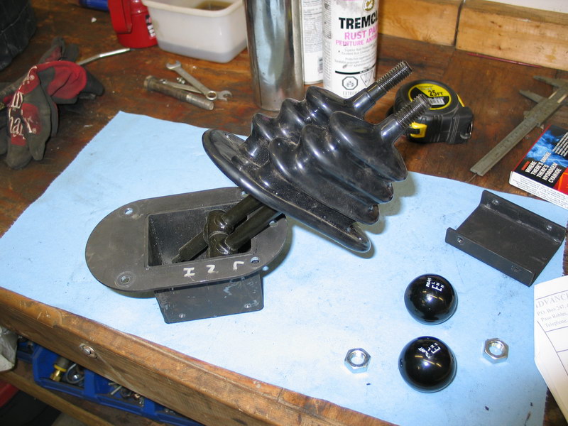 |
Remove the shifter body and slip the twin-stick shift boot (pn 302060) over the shifters and stretch the lip over the flange on the shifter body. Reinstall the jam nuts and shift knobs. | ||||||||||||||||||||||||||||||||||||||||||||||||||||||||||||||||||||||||||||||||||||||||||||||||||||||||||||||||||||||||
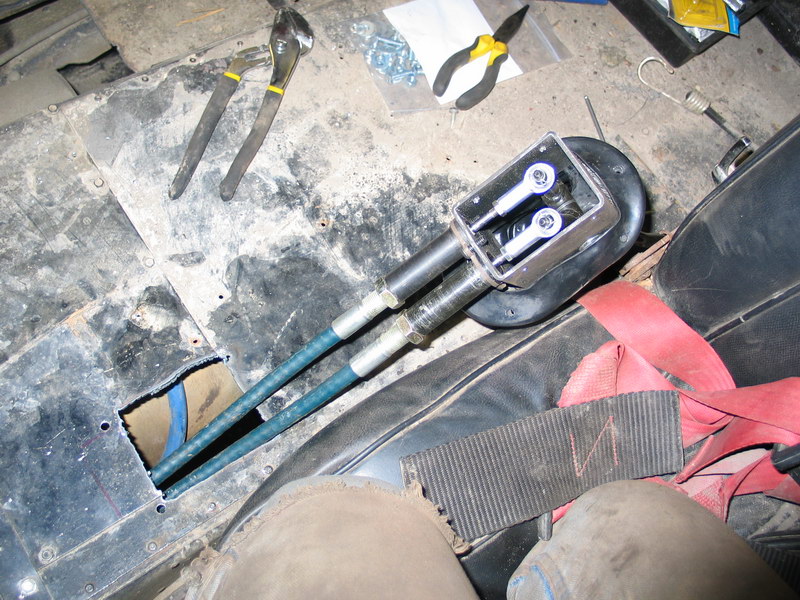 |
Pull the cables up through the cutout in the floor and insert them into the shifter body. Slip the Heim joints over the shifters, re-insert the cotter pins, and spread the legs. Fit the barrels to the shifter body and secure in place by bolting the barrel retainer plate back onto the shifter body with the three button-head cap screws. Ummmm...make sure you connect the correct cable to the correct shifter (don't ask!) |
||||||||||||||||||||||||||||||||||||||||||||||||||||||||||||||||||||||||||||||||||||||||||||||||||||||||||||||||||||||||
 |
Fit the shifter body back into the cutout and use 1/4" bolts, washers, and nuts to bolt through the shift boot , shifter body and floor. | ||||||||||||||||||||||||||||||||||||||||||||||||||||||||||||||||||||||||||||||||||||||||||||||||||||||||||||||||||||||||
 |
From underneath the vehicle, screw the shifter body bottom cover plate (pn 303302) to the shifter body using the four small #10 x 1/2" self-drilling screws (pn 722542). | ||||||||||||||||||||||||||||||||||||||||||||||||||||||||||||||||||||||||||||||||||||||||||||||||||||||||||||||||||||||||
 |
Completed twin-stick installation. | ||||||||||||||||||||||||||||||||||||||||||||||||||||||||||||||||||||||||||||||||||||||||||||||||||||||||||||||||||||||||
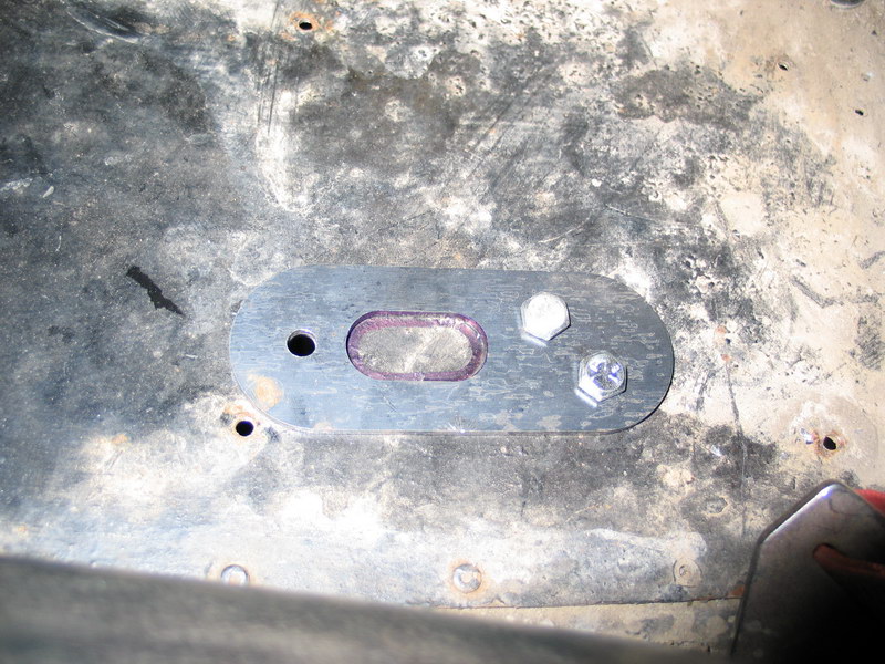 |
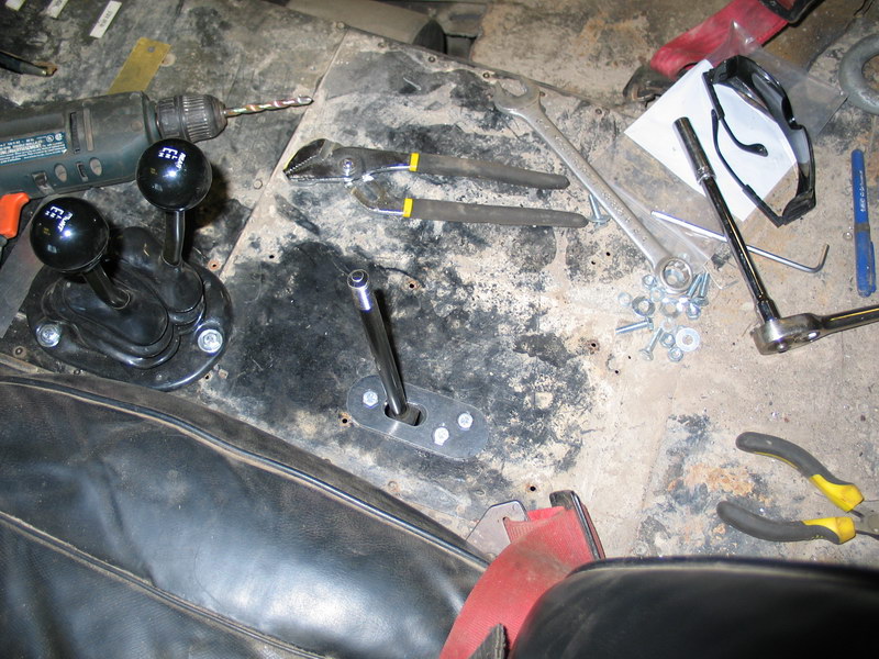
Begin the installation of the reduction box shifter by using the shifter housing mount plate (pn 340601) as a template to mark the small oval slot required for the stick to pass through the floor. | ||||||||||||||||||||||||||||||||||||||||||||||||||||||||||||||||||||||||||||||||||||||||||||||||||||||||||||||||||||||||
 |
And to drill the three 1/4" mounting bolt holes. NOTE: In this pic I have the plate the wrong way round. Of the two bolt-holes behind the slot, the front-most should be on the LEFT to properly match the shifter housing - not on the right as shown! Doh! |
||||||||||||||||||||||||||||||||||||||||||||||||||||||||||||||||||||||||||||||||||||||||||||||||||||||||||||||||||||||||
 |
These are the only holes you need to make in the floor for the shifter. | ||||||||||||||||||||||||||||||||||||||||||||||||||||||||||||||||||||||||||||||||||||||||||||||||||||||||||||||||||||||||
 |
From underneath the vehicle, pass the shift lever up through the floor and position the shifter housing under the mounting holes you drilled (note the proper orientation of the holes in this pic). It's quite helpful to have a helper to hold the shifter housing from underneath at this stage as you get everything lined up. Sandwich the floor between the shifter housing mount plate and the shifter housing using the supplied 1/4"-NF28 x 1" shifter housing bolts (pn 722543). It was here that I found another of the very few gripes with the kit. The mounting bolts supplied are 1/4"-NF28 but the three holes in the top of my shifter housing were not tapped to this. I didn't measure what they were tapped to, but thankfully it was smaller than 1/4"-NF28 so I was able to drill them out and re-tap them under the vehicle without having to disassemble the cable/shifter mechanism. |
||||||||||||||||||||||||||||||||||||||||||||||||||||||||||||||||||||||||||||||||||||||||||||||||||||||||||||||||||||||||
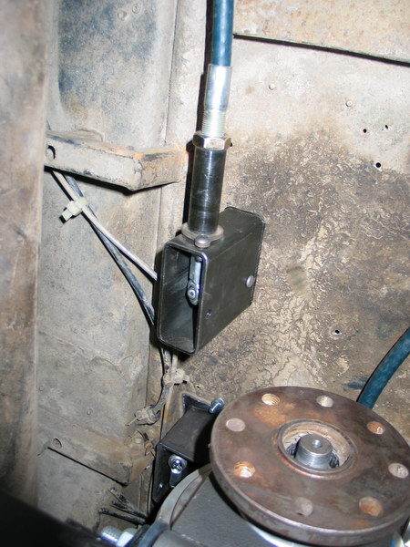 |
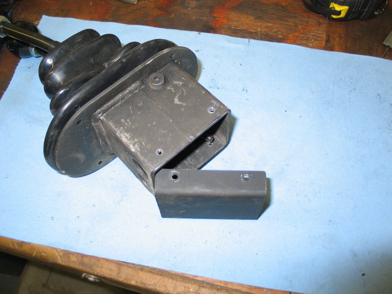
From underneath the installed shifter housing looks like this. Curiously, no bottom cover plate is provided for the reduction box shifter as it is for the twin-stick shifters? |
||||||||||||||||||||||||||||||||||||||||||||||||||||||||||||||||||||||||||||||||||||||||||||||||||||||||||||||||||||||||
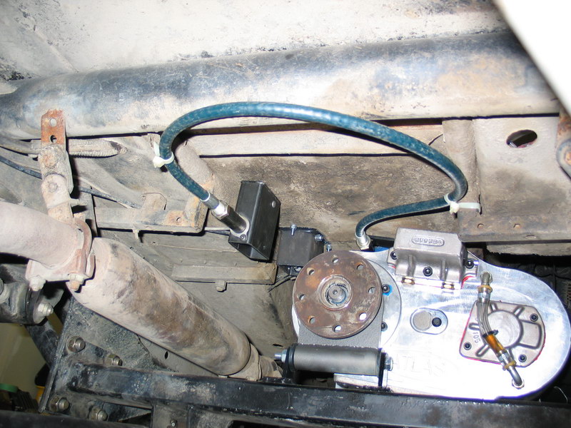 |
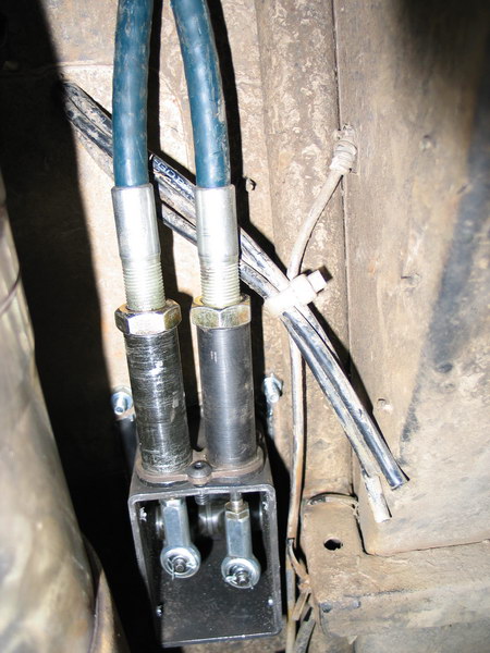
From underneath showing the cable routing and reduction box shifter. Note the zip ties to secure the cable. Be sure to keep the cables away from the exhaust. | ||||||||||||||||||||||||||||||||||||||||||||||||||||||||||||||||||||||||||||||||||||||||||||||||||||||||||||||||||||||||
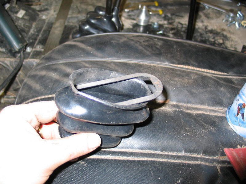 |
Back in the cockpit, insert the single stick boot ring (pn 340602) into the single stick boot (pn 340605). It lodges in the last of the wide folds. | ||||||||||||||||||||||||||||||||||||||||||||||||||||||||||||||||||||||||||||||||||||||||||||||||||||||||||||||||||||||||
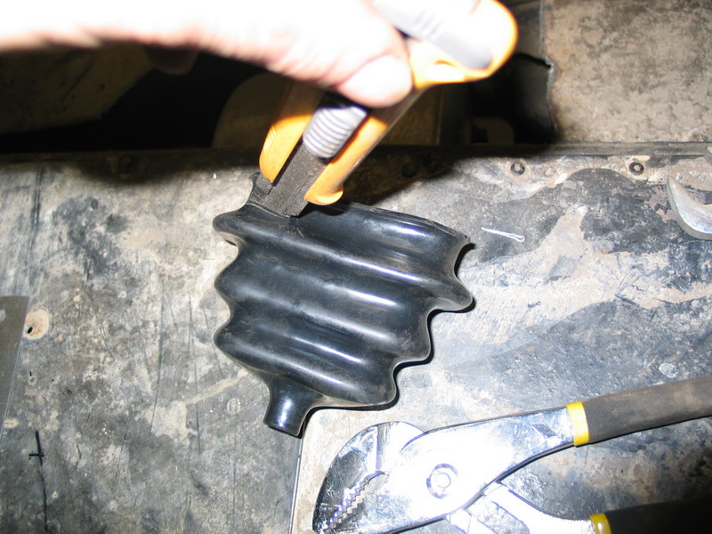 |
Trim off the excess rubber below the ring. | ||||||||||||||||||||||||||||||||||||||||||||||||||||||||||||||||||||||||||||||||||||||||||||||||||||||||||||||||||||||||
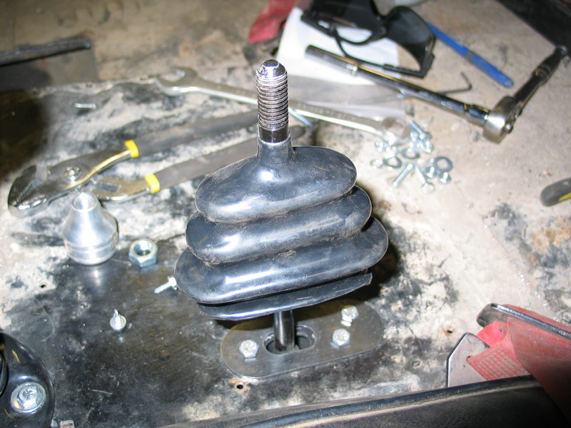 |
Slip the boot and ring over the shift lever and push it down into place. Secure by screwing through the rubber and boot ring and into the shifter housing mount plate with the #10 self-drilling screws (pn 722542) | ||||||||||||||||||||||||||||||||||||||||||||||||||||||||||||||||||||||||||||||||||||||||||||||||||||||||||||||||||||||||
 |
Finish by threading the 1/2"-NC13 jam nut (pn 303121) onto the shift lever, followed by the Shift knob (pn 340607). | ||||||||||||||||||||||||||||||||||||||||||||||||||||||||||||||||||||||||||||||||||||||||||||||||||||||||||||||||||||||||
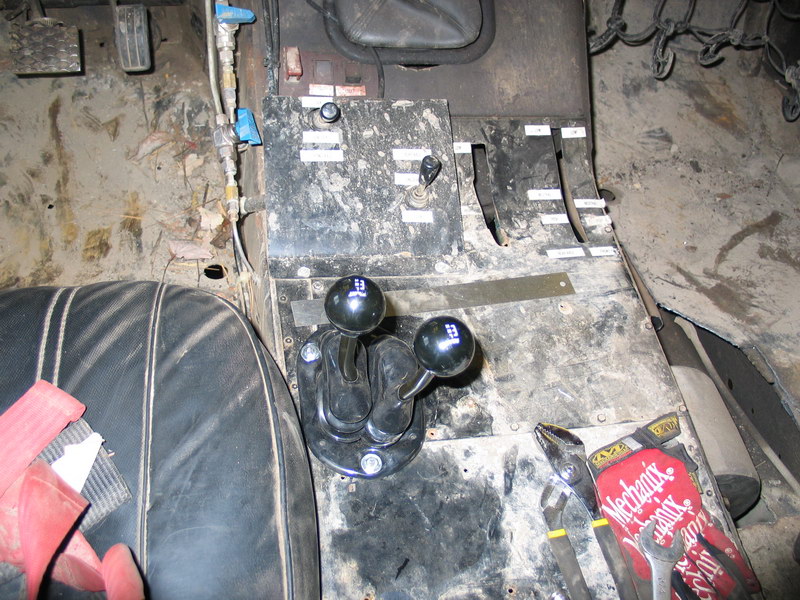
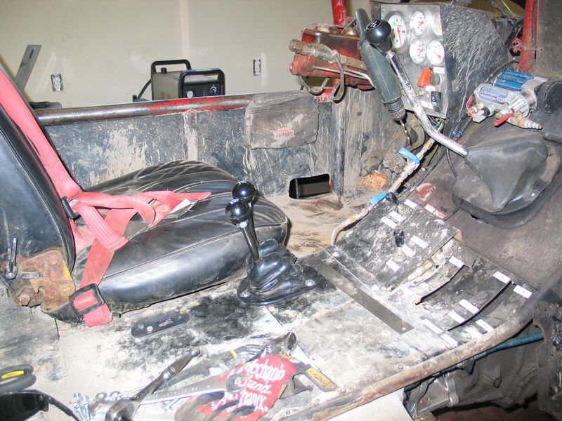
Following are a few pics of the installed shifters. There's a little more work involved in installing and adjusting the cable shifters than the traditional levers, but they offer great flexibility in mounting position. I also think they're a great option as, should the need arise, they make moving the case to a different vehicle easy.
Supporting the Atlas - Main Crossmember |
|||||||||||||||||||||||||||||||||||||||||||||||||||||||||||||||||||||||||||||||||||||||||||||||||||||||||||||||||||||||||
 |
The extreme low range of the Atlas-4SP means it will compound your motor's torque output to phenomenal levels. As a result - a sturdy mounting system for the transfer case is vital. I liked the big, heavy-duty, steel-impregnated rubber mounts used in my original setup - they are transmission mounts from a 1980 CHEVROLET K30 PICKUP V8 5.7 Liter 4BBL. In this pic you can see the original piece after 26 years of abuse on the right. On the left are the new pieces I ordered online from Advance Auto Parts for only a few bucks each. |
||||||||||||||||||||||||||||||||||||||||||||||||||||||||||||||||||||||||||||||||||||||||||||||||||||||||||||||||||||||||
Here are some other applications for the same mounts: 1969 - 1984 BLAZER / 1968 - 1984
K10 SUBURBAN / 1961 - 1967 C10 PICKUP / 1986 K10 SUBURBAN / 1968 - 1984 C10
SUBURBAN / |
|||||||||||||||||||||||||||||||||||||||||||||||||||||||||||||||||||||||||||||||||||||||||||||||||||||||||||||||||||||||||
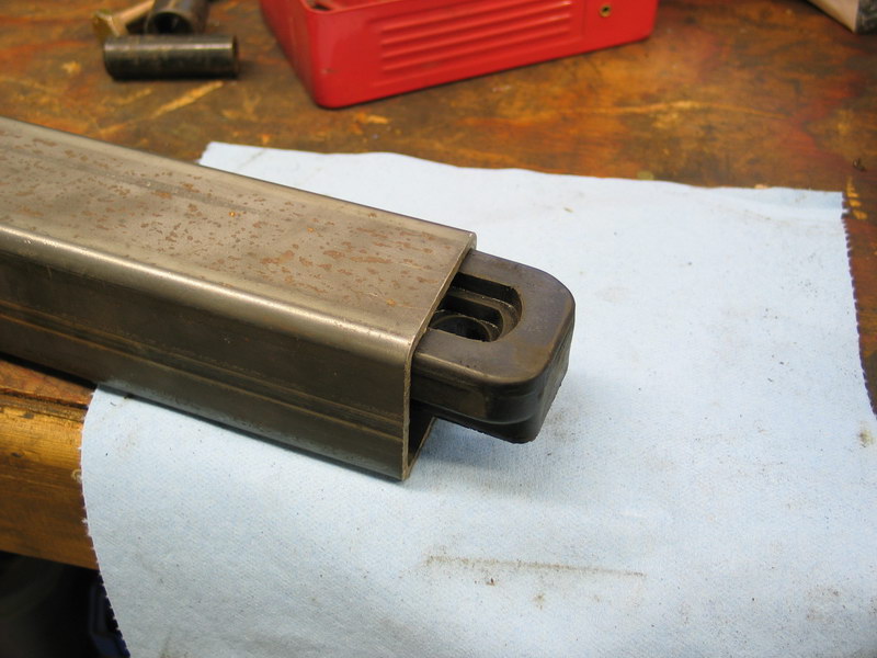 |
The smaller piece slips perfectly inside 2.5" square, 3/16" wall H.S.S. | ||||||||||||||||||||||||||||||||||||||||||||||||||||||||||||||||||||||||||||||||||||||||||||||||||||||||||||||||||||||||
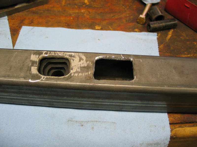 |
If you look closely at the first picture of the mounts above, you can see that the larger half (top, center of the pic) has a protrusion in the centre that fits through a slot in the crossmember and into the recess in the smaller piece. You can see the recess it fits into clearly in the left slot in this picture. The only reason the two slots are different sizes in the crossmember here is that my fab skills are legendary in their suckeyness! |
||||||||||||||||||||||||||||||||||||||||||||||||||||||||||||||||||||||||||||||||||||||||||||||||||||||||||||||||||||||||
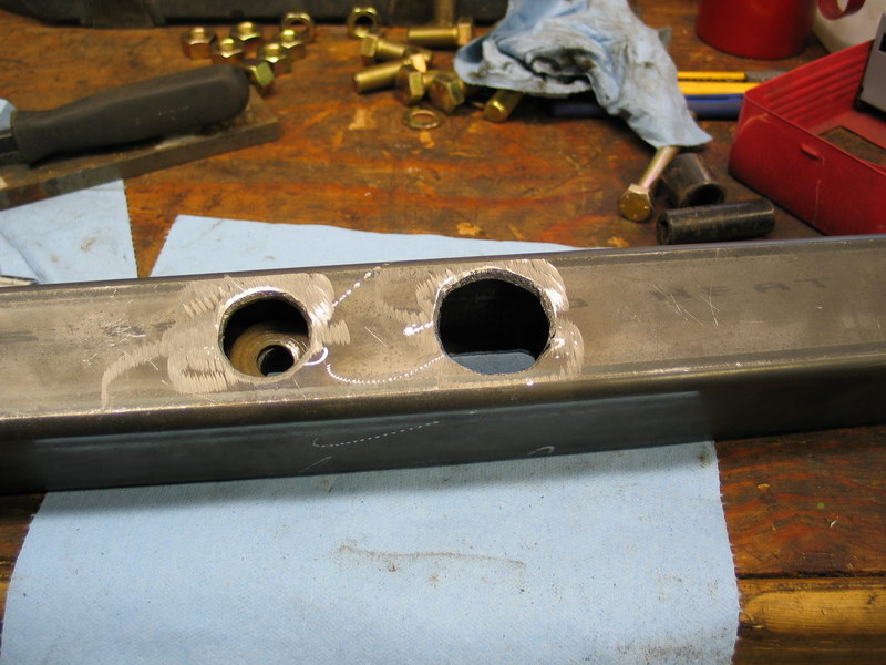 |
Opposite the slots are two round holes cut large enough for a socket to fit inside and onto the bolt heads. In this case, the right hole is intentionally larger as it needs to be big enough to insert the washers through because the ends of the crossmember will be welded closed. |
||||||||||||||||||||||||||||||||||||||||||||||||||||||||||||||||||||||||||||||||||||||||||||||||||||||||||||||||||||||||
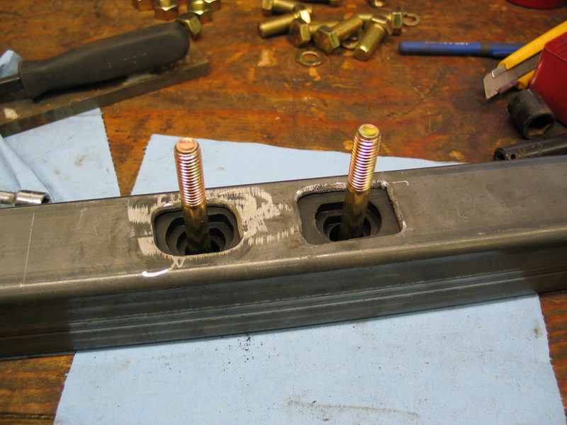 |
A 1/2"NC-13 x 5" bolt goes through the hole in the other side, through a washer, through the smaller piece of the mount, and protrudes out the top of the crossmember. | ||||||||||||||||||||||||||||||||||||||||||||||||||||||||||||||||||||||||||||||||||||||||||||||||||||||||||||||||||||||||
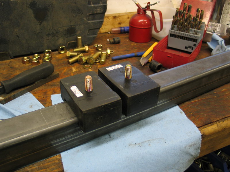 |
The larger pieces of the mount go over the bolts and fit perfectly over the 2.5" square tubing. | ||||||||||||||||||||||||||||||||||||||||||||||||||||||||||||||||||||||||||||||||||||||||||||||||||||||||||||||||||||||||
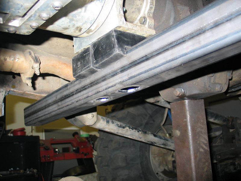 |
I then drilled two holes in the mounting foot of the adapter and bolted on the mount / crossmember with washers and locknuts. | ||||||||||||||||||||||||||||||||||||||||||||||||||||||||||||||||||||||||||||||||||||||||||||||||||||||||||||||||||||||||
 |
Here I am test-fitting the crossmember to figure out where it needs to be attached to the vehicle. | ||||||||||||||||||||||||||||||||||||||||||||||||||||||||||||||||||||||||||||||||||||||||||||||||||||||||||||||||||||||||
 |
In order to get the crossmember positioned vertically in the vehicle where I wanted, I had to use a rectangular 3/8" steel spacer between the rubber mounts and the bottom of the transfer case adapter. You can see it in this pic under the nuts and washers. |
||||||||||||||||||||||||||||||||||||||||||||||||||||||||||||||||||||||||||||||||||||||||||||||||||||||||||||||||||||||||
 |
The assembled crossmember / mount looks like this. | ||||||||||||||||||||||||||||||||||||||||||||||||||||||||||||||||||||||||||||||||||||||||||||||||||||||||||||||||||||||||
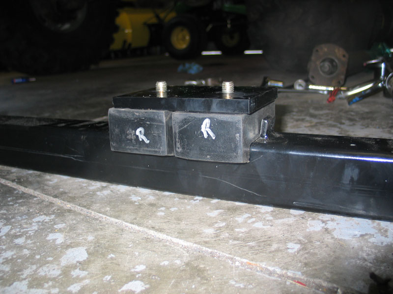 |
Close-up of the mount. You can clearly see the 3/8" thick spacer on top of the rubber mounts. | ||||||||||||||||||||||||||||||||||||||||||||||||||||||||||||||||||||||||||||||||||||||||||||||||||||||||||||||||||||||||
 |
Crossmember installed. It's mounted to the frame with eight 5/8" fine thread grade 8 bolts using red Loctite. |
||||||||||||||||||||||||||||||||||||||||||||||||||||||||||||||||||||||||||||||||||||||||||||||||||||||||||||||||||||||||
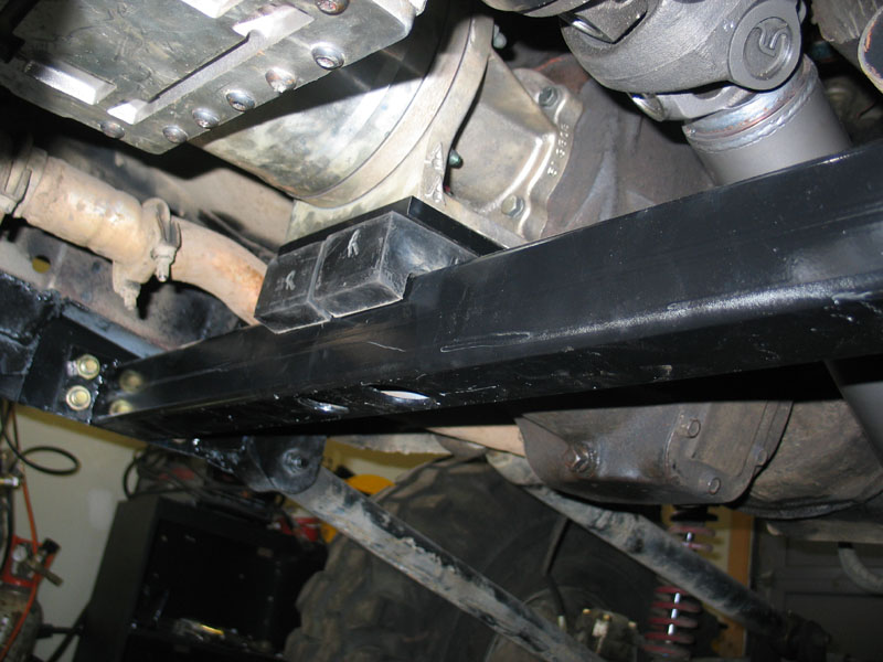 |
Close-up of the mount installed. | ||||||||||||||||||||||||||||||||||||||||||||||||||||||||||||||||||||||||||||||||||||||||||||||||||||||||||||||||||||||||
 |
View of the crossmember and mount from below and behind. | ||||||||||||||||||||||||||||||||||||||||||||||||||||||||||||||||||||||||||||||||||||||||||||||||||||||||||||||||||||||||
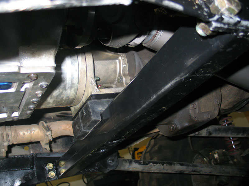 |
Final view of the crossmember and mount where it supports the transfer case adapter. This simple setup should provide excellent vertical support to the drivetrain. |
||||||||||||||||||||||||||||||||||||||||||||||||||||||||||||||||||||||||||||||||||||||||||||||||||||||||||||||||||||||||
Supporting the Atlas - the Roark Fabworks Atlas Mount KitA sturdy crossmember is a given - but with a case capable of this kind of torque multiplication a little extra thought is required regarding its mounting requirements. With two widely spaced motor mounts and a single central transmission crossmember what we have is a 3-legged stool arrangement (thanks to Randii for the metaphor). Obviously our drivetrain needs to be supported vertically and laterally, lest it depart the vehicle in a manner not altogether desired - and the stock-like "bar-stool" arrangement fills this need well. However, the drivetrain also needs to be supported, or rather, "restrained' rotationally - so that it doesn't torque itself all over the place. It is here that the 3-legged bar stool arrangement may not be adequate for a drivetrain capable of multiplying a few hundred ft/lbs of torque by two or three hundred times! To assist in rotational rigidity, as well as to help support the weight of the fairly lengthy drivetrain, I turned to a really nifty product from an outfit called Roark Fabworks. Like most great things it's deceptively simple - along the lines of "why didn't I think of that?" Well, in my case, even if I had we all know how legendarily appalling my fab skills are - so a neat little kit like this is just perfect. |
|||||||||||||||||||||||||||||||||||||||||||||||||||||||||||||||||||||||||||||||||||||||||||||||||||||||||||||||||||||||||
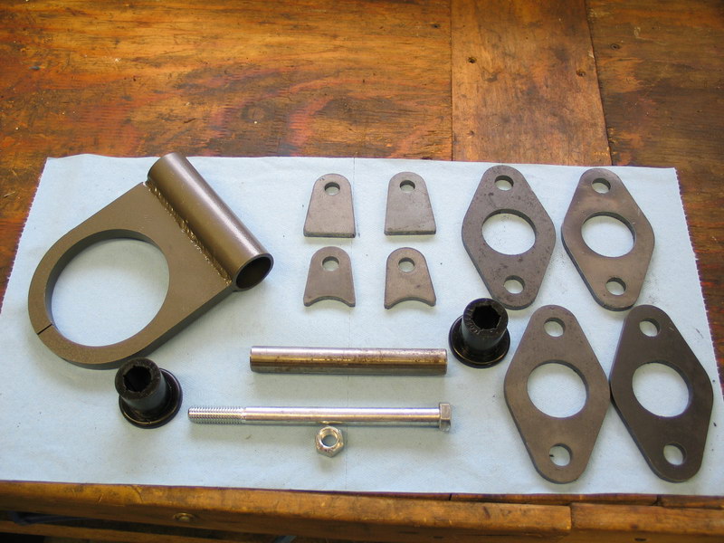 |
This is the kit. The main component is the support ring (top left) that clamps around the tailshaft housing of the Atlas. The ring is then supported by bushings and clamped between weld-on tabs. Some very nice flanges are also included for use with tubular crossmembers. They are sized for those using 1.75" OD tube. |
||||||||||||||||||||||||||||||||||||||||||||||||||||||||||||||||||||||||||||||||||||||||||||||||||||||||||||||||||||||||
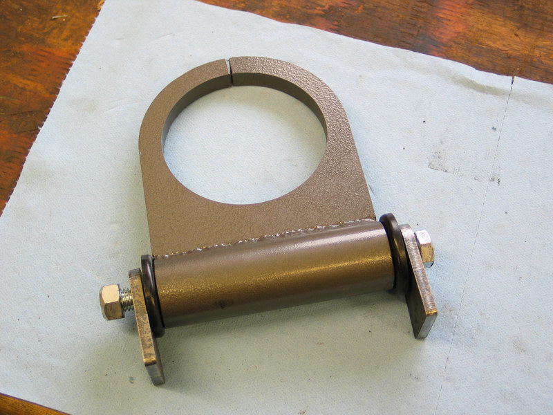 |
Here we see the support ring loosely assembled with the supplied weld-on tabs. | ||||||||||||||||||||||||||||||||||||||||||||||||||||||||||||||||||||||||||||||||||||||||||||||||||||||||||||||||||||||||
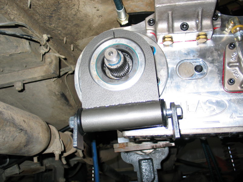 |
This is how the support clamps to the tailshaft housing of the Atlas. It fits both the regular and the "short" competition tailshaft housing. This is a trial-fitting picture - note that there is plenty of clearance, even with the short housing like mine, for the Roark support to sit flush with the end of the housing. |
||||||||||||||||||||||||||||||||||||||||||||||||||||||||||||||||||||||||||||||||||||||||||||||||||||||||||||||||||||||||
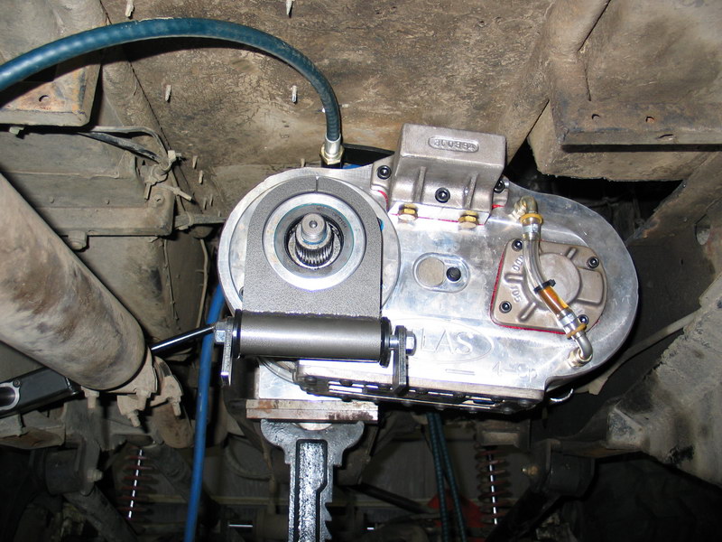 |
If you are using yokes on your Atlas the Roark mount will slip right on. If you are using a flange, you will need to remove the flange to position the mount over the tailshaft housing. With the mount in place, tighten the small Allen screw that will clamp the mount tightly to the tailshaft housing. |
||||||||||||||||||||||||||||||||||||||||||||||||||||||||||||||||||||||||||||||||||||||||||||||||||||||||||||||||||||||||
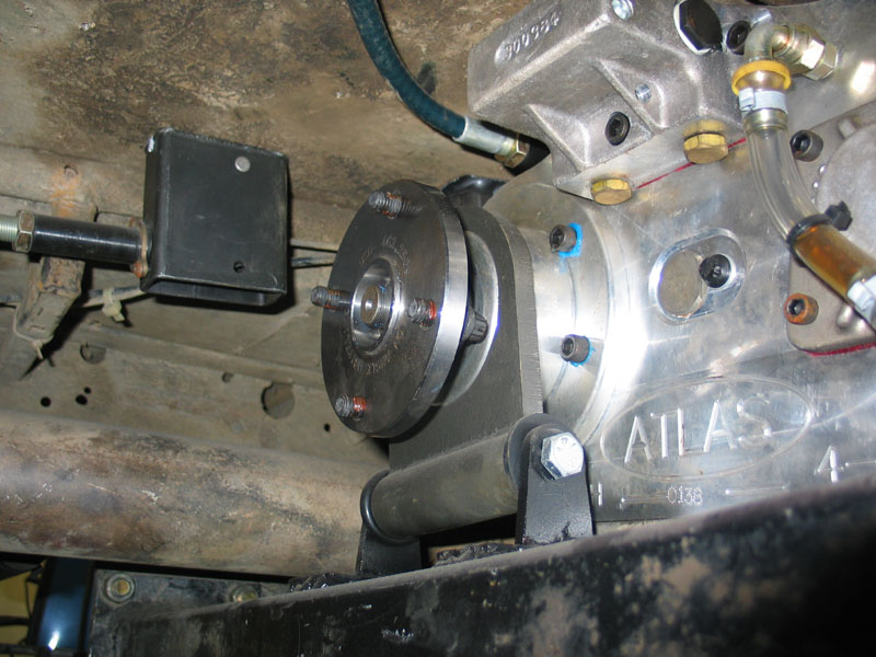 |
You can install the mount in any orientation. Once you have the position selected, you can tighten the long bolt through the bushings and weld the tabs in place. If you don't already have a crossmember in the right location, the supplied flanges can be very handy in fabricating a tubular crossmember to support the mount. I was lucky and the mount lined up perfectly with my 4-link suspension crossmember. |
||||||||||||||||||||||||||||||||||||||||||||||||||||||||||||||||||||||||||||||||||||||||||||||||||||||||||||||||||||||||
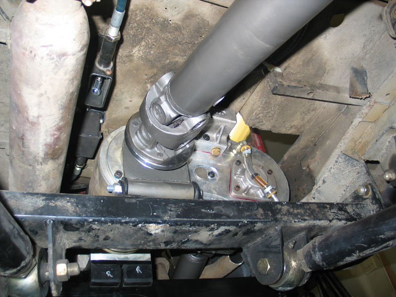 |
It's a trick little kit that would make an excellent addition to any Atlas. | ||||||||||||||||||||||||||||||||||||||||||||||||||||||||||||||||||||||||||||||||||||||||||||||||||||||||||||||||||||||||
Controlling Rotational Moment - Building a Torque Arm |
|||||||||||||||||||||||||||||||||||||||||||||||||||||||||||||||||||||||||||||||||||||||||||||||||||||||||||||||||||||||||
|
Even with the Roark Fabworks mount, I was still concerned about rotational stability, especially with the extreme torque multiplication of the Atlas-4SP, the aluminum transfer case mount, and reports of mounting bolts either stripping loose or breaking. There is a small threaded boss on the side of the transfer case adapter, on the side of the transmission-side flange. |
||||||||||||||||||||||||||||||||||||||||||||||||||||||||||||||||||||||||||||||||||||||||||||||||||||||||||||||||||||||||
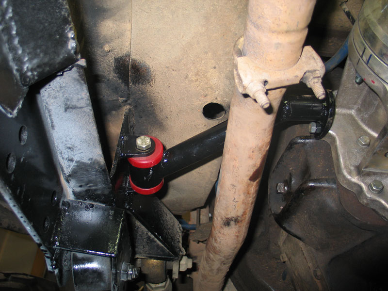 |
I used it to bolt on a flange that I welded to a tubular torque arm which I then attached to the frame with a bushing mount. | ||||||||||||||||||||||||||||||||||||||||||||||||||||||||||||||||||||||||||||||||||||||||||||||||||||||||||||||||||||||||
 |
Shot from below. It won't win any awards for fabrication but it should do the job. | ||||||||||||||||||||||||||||||||||||||||||||||||||||||||||||||||||||||||||||||||||||||||||||||||||||||||||||||||||||||||
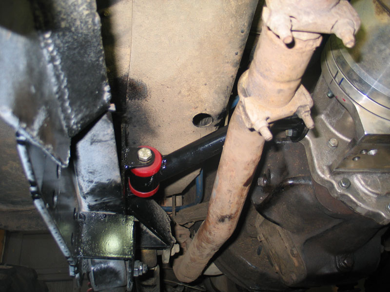 |
My theory is that, by adding this additional support perpendicular to the drivetrain, the drivetrain won't rotate under torque enough to cause any problems. | ||||||||||||||||||||||||||||||||||||||||||||||||||||||||||||||||||||||||||||||||||||||||||||||||||||||||||||||||||||||||
Heavy Duty Driveshafts - High Angle Driveline 1-ton 1350 C.V. Shafts with 1410 axle yokes |
|||||||||||||||||||||||||||||||||||||||||||||||||||||||||||||||||||||||||||||||||||||||||||||||||||||||||||||||||||||||||
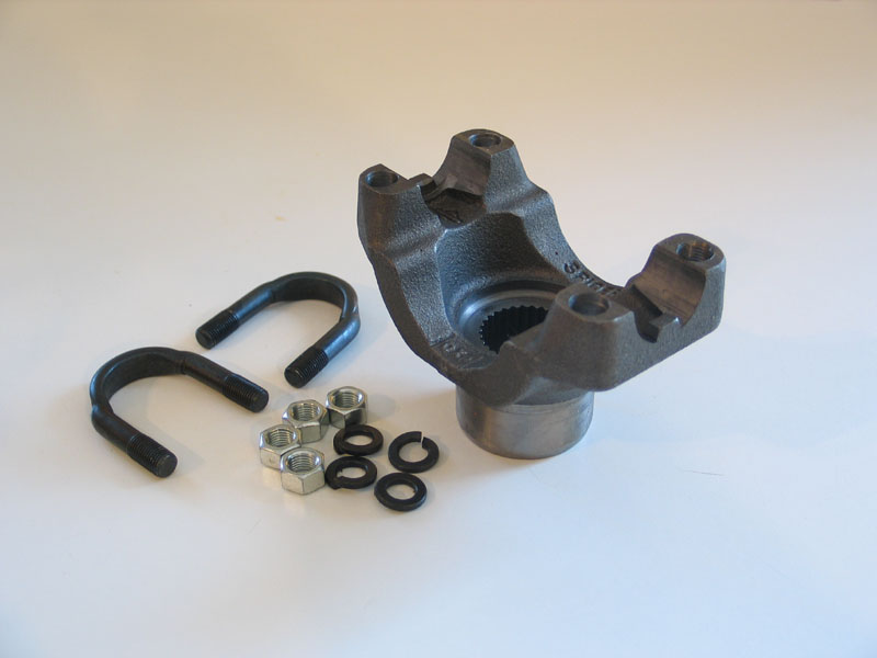 |
With a kick-ass, one-of-a-kind new 4-speed transfer case installed, I wanted bulletproof driveshafts to match. For my new shafts I turned to one of the most highly respected names in the business - High Angle Driveline (HAD). While I was at it I also decided to upgrade the puny stock 1310 joint of my front Dana 60 to this 1410 monster from HAD. |
||||||||||||||||||||||||||||||||||||||||||||||||||||||||||||||||||||||||||||||||||||||||||||||||||||||||||||||||||||||||
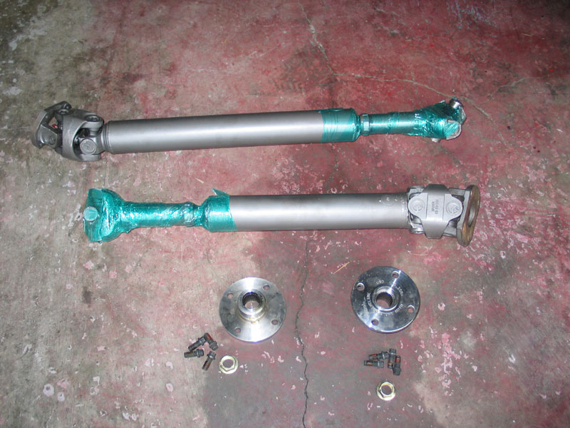 |
I had already been running one of HAD's 1-ton 1350 CV shafts in the rear, with a 1410 joint at the 14-Bolt pinion. Since the Atlas-4SP is actually some 4" or so shorter than my old 203/D20 doubler, I sent the rear shaft back to HAD to lengthen and asked Jess to make me a front shaft to match - 1350 CV joint at the 'case and 1410 joint at the axle. I also needed two of HAD's patented CV flanges to install in the Atlas. They come with flange-to-CV bolts and new locknuts to secure the flanges to the Atlas output shafts. |
||||||||||||||||||||||||||||||||||||||||||||||||||||||||||||||||||||||||||||||||||||||||||||||||||||||||||||||||||||||||
 |
The shafts arrived in these super-tough tubes, complete with wooden end-caps screwed on. | ||||||||||||||||||||||||||||||||||||||||||||||||||||||||||||||||||||||||||||||||||||||||||||||||||||||||||||||||||||||||
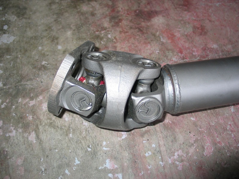 |
This is the 1-ton 1350 CV joint... | ||||||||||||||||||||||||||||||||||||||||||||||||||||||||||||||||||||||||||||||||||||||||||||||||||||||||||||||||||||||||
 |
... and this is the 1410 joint at the axle end of the shaft. | ||||||||||||||||||||||||||||||||||||||||||||||||||||||||||||||||||||||||||||||||||||||||||||||||||||||||||||||||||||||||
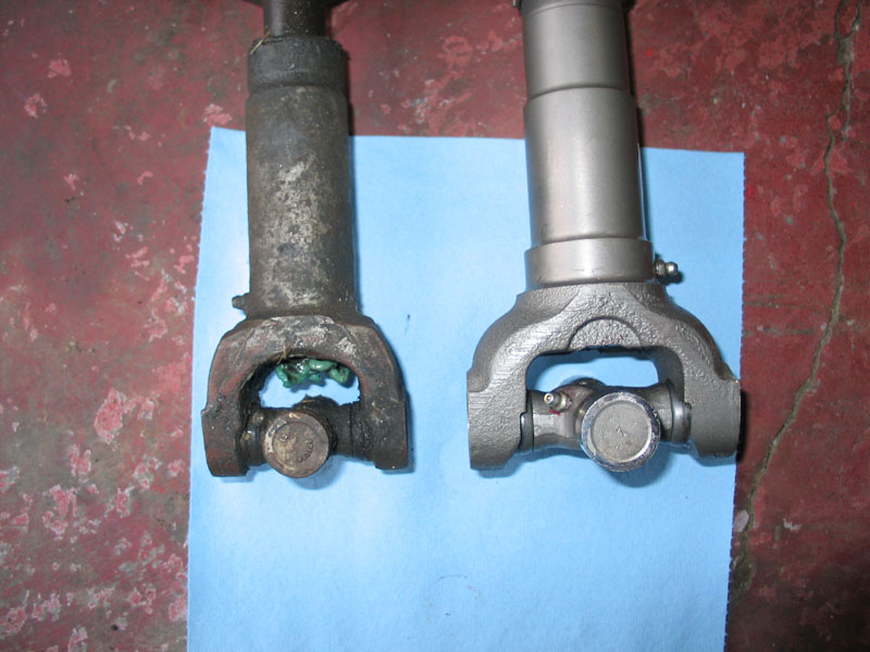 |
Comparison between the old 1310 shaft on the left, and the new 1410 shaft on the right. | ||||||||||||||||||||||||||||||||||||||||||||||||||||||||||||||||||||||||||||||||||||||||||||||||||||||||||||||||||||||||
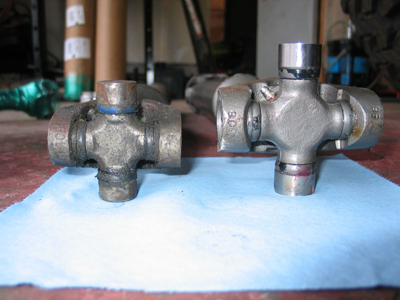 |
1310 on left, 1410 on right. | ||||||||||||||||||||||||||||||||||||||||||||||||||||||||||||||||||||||||||||||||||||||||||||||||||||||||||||||||||||||||
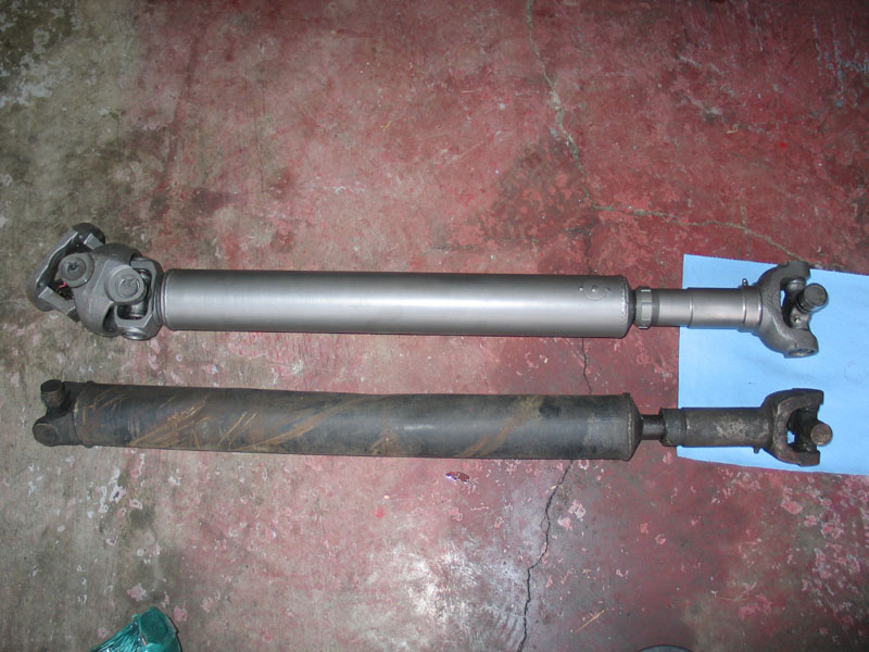 |
The new front shaft above the old, single-cardan shaft. | ||||||||||||||||||||||||||||||||||||||||||||||||||||||||||||||||||||||||||||||||||||||||||||||||||||||||||||||||||||||||
 |
Comparison between the transfer-case ends of the new and old shafts. | ||||||||||||||||||||||||||||||||||||||||||||||||||||||||||||||||||||||||||||||||||||||||||||||||||||||||||||||||||||||||
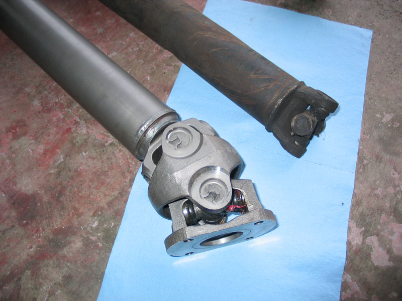 |
1310 single-cardan joint vs. 1350 CV joint. | ||||||||||||||||||||||||||||||||||||||||||||||||||||||||||||||||||||||||||||||||||||||||||||||||||||||||||||||||||||||||
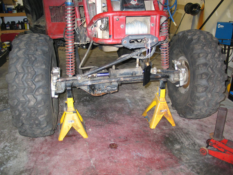 |
Before installing the new driveshafts the first step was to install the 1410 yoke on the Dana 60 pinion. Start by jacking up the front wheels and placing the front axle on jack stands so you can rotate the pinion freely. |
||||||||||||||||||||||||||||||||||||||||||||||||||||||||||||||||||||||||||||||||||||||||||||||||||||||||||||||||||||||||
 |
Before disassembling anything, use a dial-type inch-pound torque wrench on the pinion nut (1-5/16") to measure the torque required to rotate the pinion, and record this value. You must measure the torque it takes to rotate the pinion by the nut while it is in motion. If you simply measure the torque it takes to start the pinion rotating you will get an artificially high reading. This is why a dial-indicating torque wrench is best as you can start the pinion rotating, then read the indication from the dial while you continue to rotate the pinion. In my case it was about 25-30 in/lbs |
||||||||||||||||||||||||||||||||||||||||||||||||||||||||||||||||||||||||||||||||||||||||||||||||||||||||||||||||||||||||
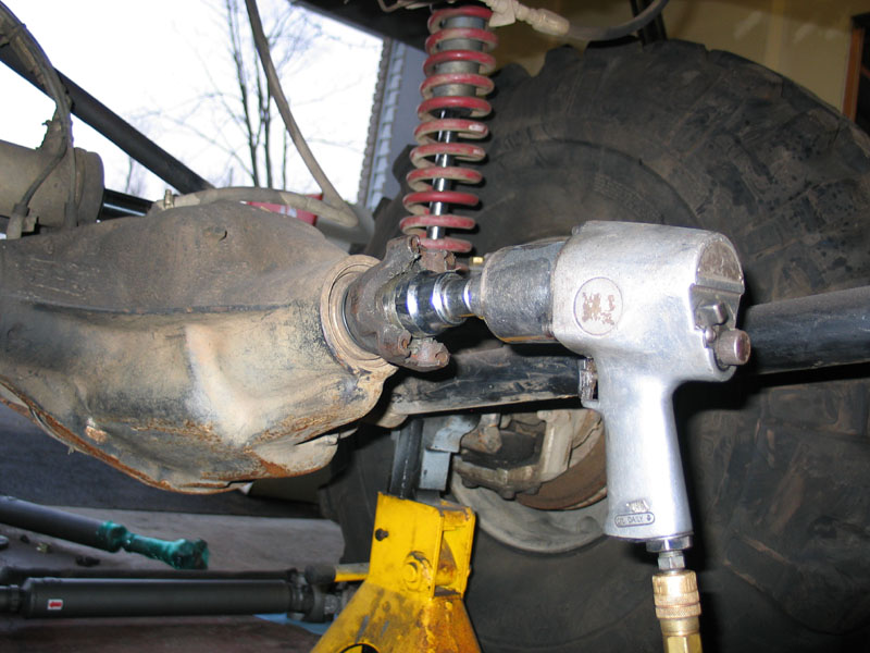 |
Remove the pinion nut and the old yoke. | ||||||||||||||||||||||||||||||||||||||||||||||||||||||||||||||||||||||||||||||||||||||||||||||||||||||||||||||||||||||||
 |
With the old yoke removed, marvel at the difference between the puny 1310 piece and the beefy 1410 yoke. | ||||||||||||||||||||||||||||||||||||||||||||||||||||||||||||||||||||||||||||||||||||||||||||||||||||||||||||||||||||||||
 |
I love big, Heavy Duty upgrades! | ||||||||||||||||||||||||||||||||||||||||||||||||||||||||||||||||||||||||||||||||||||||||||||||||||||||||||||||||||||||||
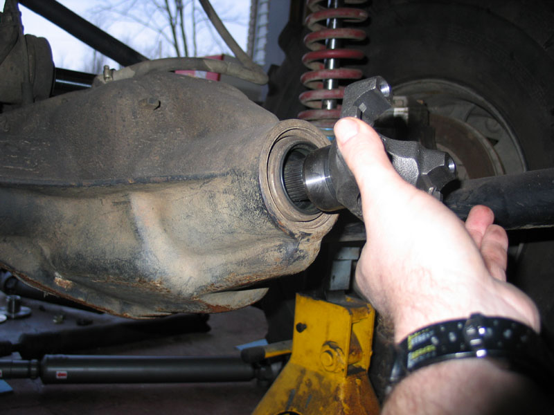 |
Slide the new yoke onto the pinion... | ||||||||||||||||||||||||||||||||||||||||||||||||||||||||||||||||||||||||||||||||||||||||||||||||||||||||||||||||||||||||
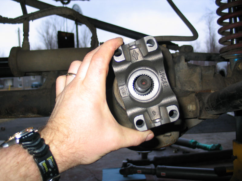 |
...making sure the splines line up and the yoke seats against the seal. | ||||||||||||||||||||||||||||||||||||||||||||||||||||||||||||||||||||||||||||||||||||||||||||||||||||||||||||||||||||||||
 |
Install a new flanged lock nut and tighten to the minimum torque spec for the axle (220 ft/lbs for a D60). Reinstall the inch-pound torque wrench on the pinion nut and again measure the torque required to rotate the pinion. Compare this value to that which you previously recorded. If the second value is approx. 1-5 in/lbs more than the first you are done. If not, continue tightening the pinion nut in small increments until you reach a point where the torque-to-rotate is approx. 1-5 in/lbs more than it was originally. Do not exceed the maximum torque value for the axle (280 ft/lbs for a D60). |
||||||||||||||||||||||||||||||||||||||||||||||||||||||||||||||||||||||||||||||||||||||||||||||||||||||||||||||||||||||||
 |
The next step is to install the flanges onto the Atlas. A note on the flanges. If you are planning on using HAD 1350 flanges and driveshafts with your Atlas, you actually need to order your Atlas with 1350 non-cv yokes. This is because the HAD flanges use the same seal diameter as the Atlas non-cv yokes. Of course you could always order your Atlas from HAD and get it with the flanges installed. |
||||||||||||||||||||||||||||||||||||||||||||||||||||||||||||||||||||||||||||||||||||||||||||||||||||||||||||||||||||||||
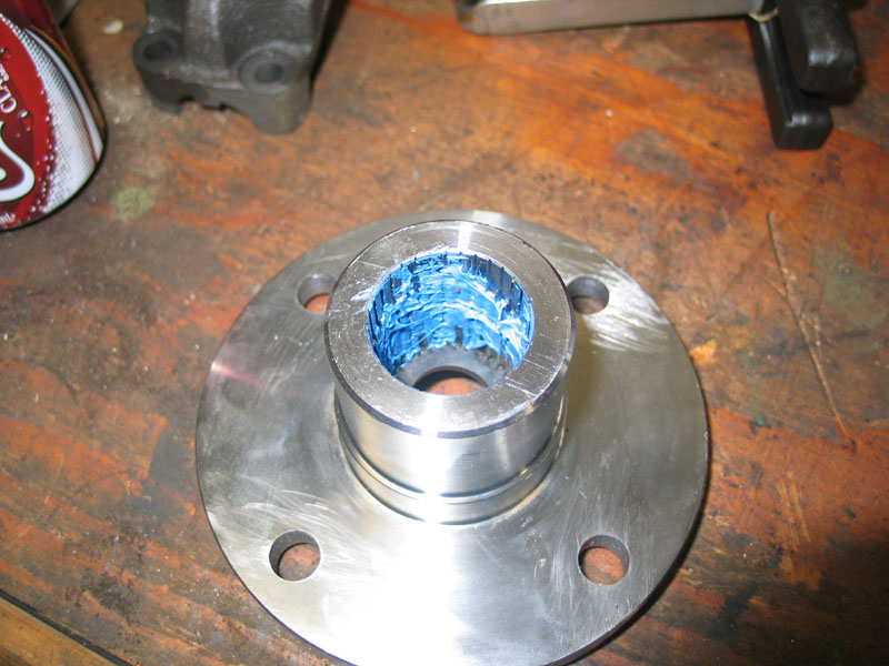 |
The next six steps apply to both front and rear flanges. 1 - Smear a little blue RTV on the inside to prevent oil from leaking past the splines. |
||||||||||||||||||||||||||||||||||||||||||||||||||||||||||||||||||||||||||||||||||||||||||||||||||||||||||||||||||||||||
 |
2 - Insert the little rubber washer (that would have come off when you removed the yokes the Atlas shipped with). | ||||||||||||||||||||||||||||||||||||||||||||||||||||||||||||||||||||||||||||||||||||||||||||||||||||||||||||||||||||||||
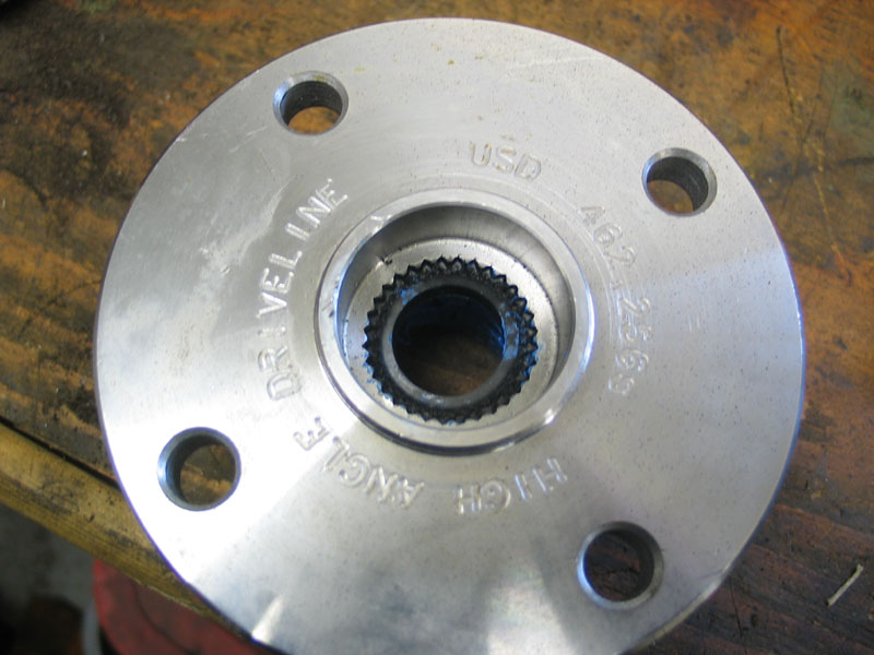 |
Rubber washer installed. | ||||||||||||||||||||||||||||||||||||||||||||||||||||||||||||||||||||||||||||||||||||||||||||||||||||||||||||||||||||||||
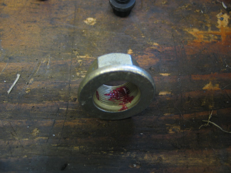 |
3 - The flange nuts are locking-type, but I feel a little dab of red Loctite is good insurance. | ||||||||||||||||||||||||||||||||||||||||||||||||||||||||||||||||||||||||||||||||||||||||||||||||||||||||||||||||||||||||
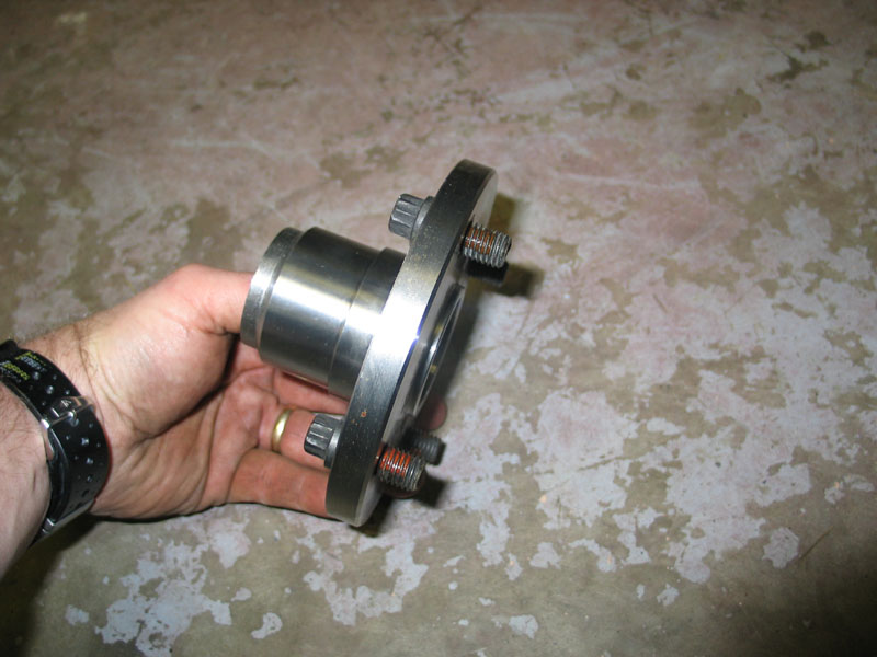 |
4 - Because of limited clearance between the transfer case and the back of the flange you need to pre-install the 12-point bolts that secure the driveshaft. | ||||||||||||||||||||||||||||||||||||||||||||||||||||||||||||||||||||||||||||||||||||||||||||||||||||||||||||||||||||||||
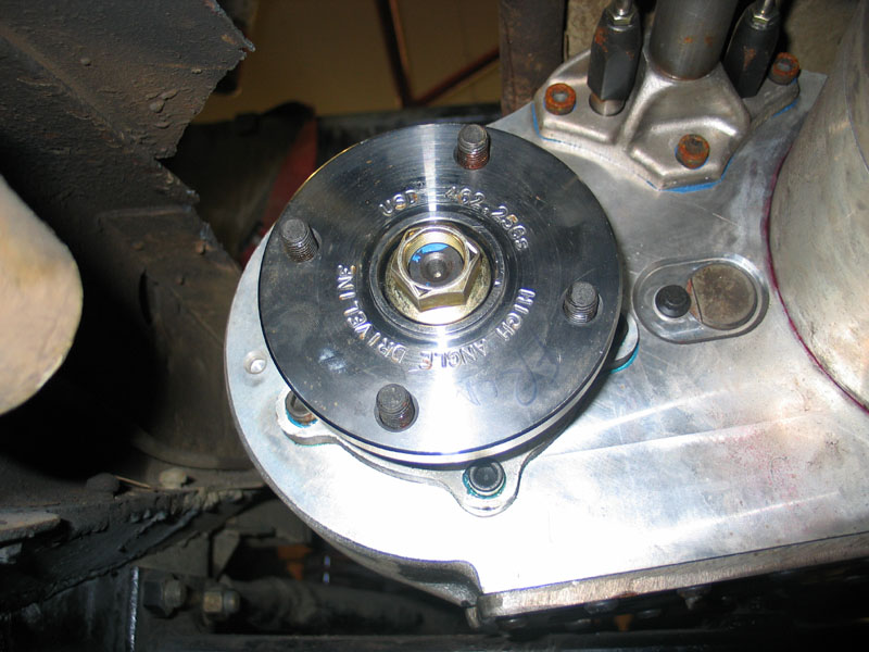 |
5 - Slip the flange over the splines and install the locknut. | ||||||||||||||||||||||||||||||||||||||||||||||||||||||||||||||||||||||||||||||||||||||||||||||||||||||||||||||||||||||||
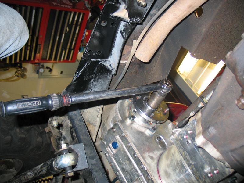 |
6 - Torque the flange nut to 150 ft/lbs | ||||||||||||||||||||||||||||||||||||||||||||||||||||||||||||||||||||||||||||||||||||||||||||||||||||||||||||||||||||||||
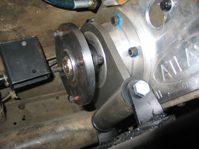 |
Rear flange installed. | ||||||||||||||||||||||||||||||||||||||||||||||||||||||||||||||||||||||||||||||||||||||||||||||||||||||||||||||||||||||||
 |
Hold the driveshaft in place and and start the bolts into the threaded holes in the CV joint flange with your fingers. Because of the limited clearance, there is insufficient room to get a wrench on the bolt heads until they are threaded partly into the driveshaft. You may find that you have to use needle-nose pliers or vice-grips to tighten the bolts sufficiently to get enough room to get a wrench on the bolt heads. |
||||||||||||||||||||||||||||||||||||||||||||||||||||||||||||||||||||||||||||||||||||||||||||||||||||||||||||||||||||||||
 |
The 12-point bolts are tightened with 12-point 12mm box-end wrench. The bolts come with thread locker pre-installed so you needn't add any. You want to tighten the bolts to about 35 ft/lbs. It's impossible to get a torque wrench in there, so you'll have to use a "calibrated hand". Unless you're a gorilla, almost as tight as you can get them with the 12mm wrench is probably pretty close. |
||||||||||||||||||||||||||||||||||||||||||||||||||||||||||||||||||||||||||||||||||||||||||||||||||||||||||||||||||||||||
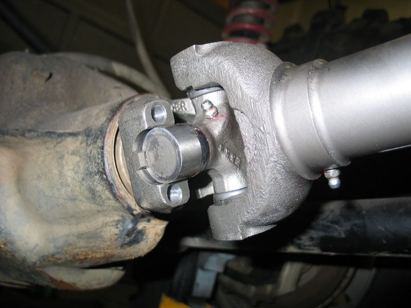 |
At the axle end of the shaft, set the U-joint in place in the yoke. Make sure the U-joint caps are seated completely and evenly between the little locating tabs on the yoke. | ||||||||||||||||||||||||||||||||||||||||||||||||||||||||||||||||||||||||||||||||||||||||||||||||||||||||||||||||||||||||
 |
Then install the U-bolts, lock washers, and nuts. | ||||||||||||||||||||||||||||||||||||||||||||||||||||||||||||||||||||||||||||||||||||||||||||||||||||||||||||||||||||||||
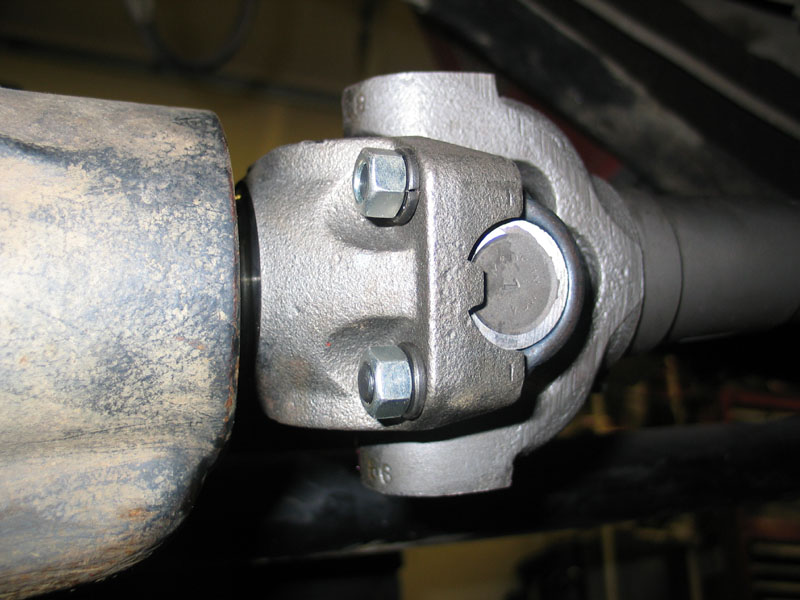 |
Tighten the nuts evenly with a 9/16" wrench. | ||||||||||||||||||||||||||||||||||||||||||||||||||||||||||||||||||||||||||||||||||||||||||||||||||||||||||||||||||||||||
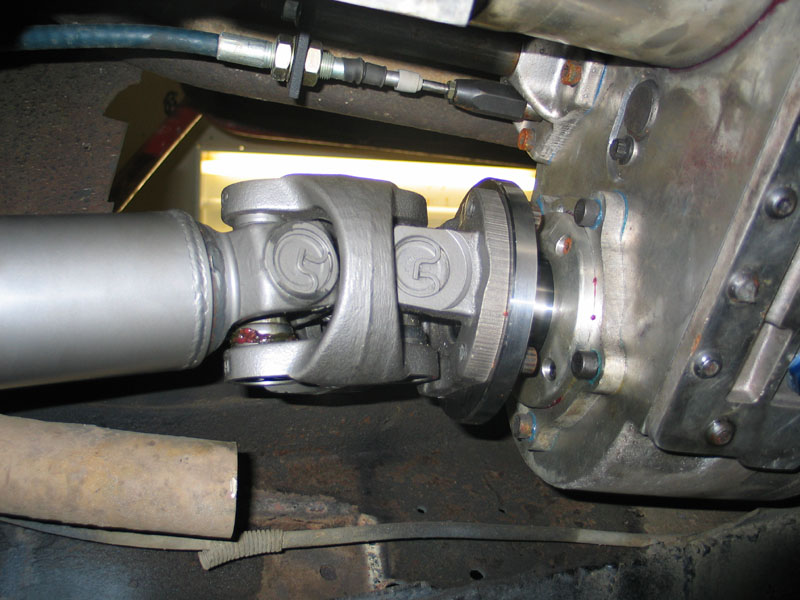 |
Transfer case end of front shaft. | ||||||||||||||||||||||||||||||||||||||||||||||||||||||||||||||||||||||||||||||||||||||||||||||||||||||||||||||||||||||||
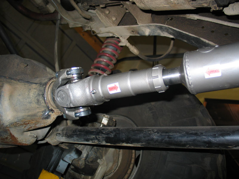 |
Axle end of front shaft. | ||||||||||||||||||||||||||||||||||||||||||||||||||||||||||||||||||||||||||||||||||||||||||||||||||||||||||||||||||||||||
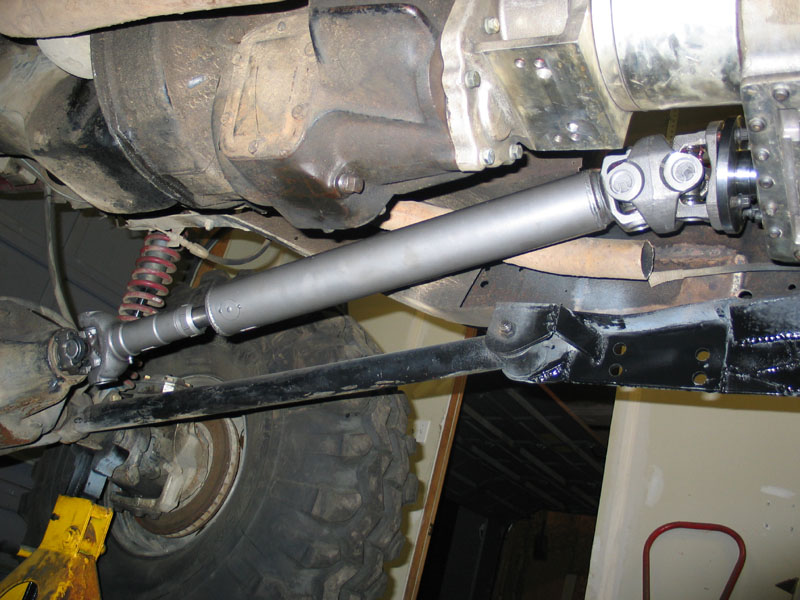 |
Front shaft installed. Doh! I think I just made the Dana 60 R&P the weak link. |
||||||||||||||||||||||||||||||||||||||||||||||||||||||||||||||||||||||||||||||||||||||||||||||||||||||||||||||||||||||||
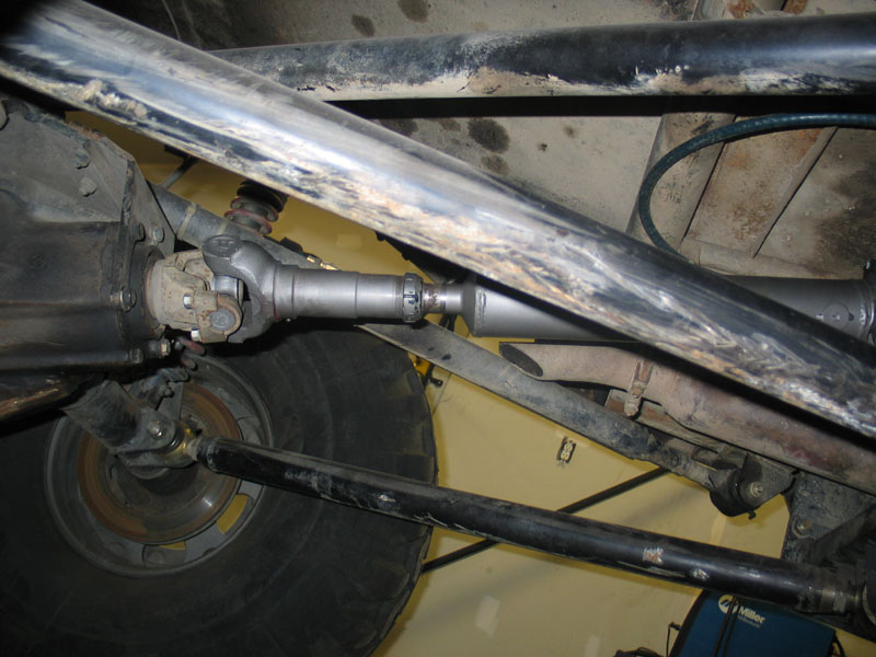 |
Rear shaft installed. | ||||||||||||||||||||||||||||||||||||||||||||||||||||||||||||||||||||||||||||||||||||||||||||||||||||||||||||||||||||||||
The Finished InstallA gallery of shots of the installed Atlas-4SP, Roark Fabworks Mount, and High Angle Driveline 1350 CV shafts.
ConclusionReliable, strong, short, lightweight, four-speed, synchronized, leak free, and with long-term proven reliability - it's my considered opinion that the Atlas four speed transfer case simply has no equal in the market - simple as that. The following table, showing my available gear ratios, really says it all.
Combined with the trick Roark mount and bulletproof CV driveshafts from High Angle the Wolf now has a killer drivetrain that can go toe to toe with any other on the planet. Period. References:
|
|||||||||||||||||||||||||||||||||||||||||||||||||||||||||||||||||||||||||||||||||||||||||||||||||||||||||||||||||||||||||
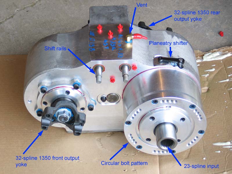
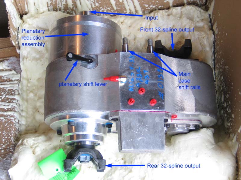
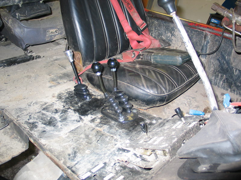
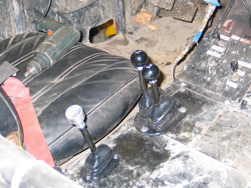

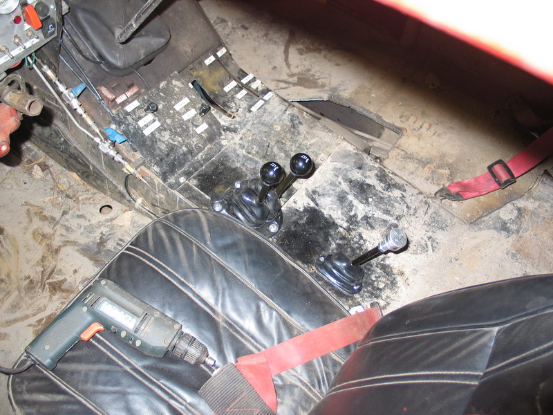
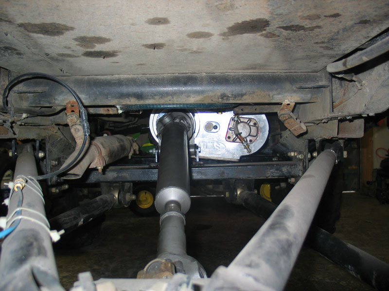
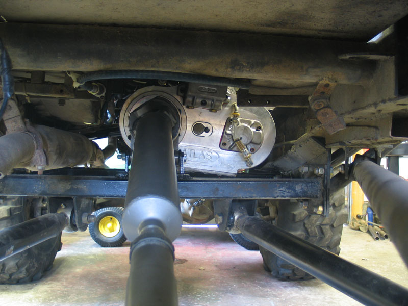
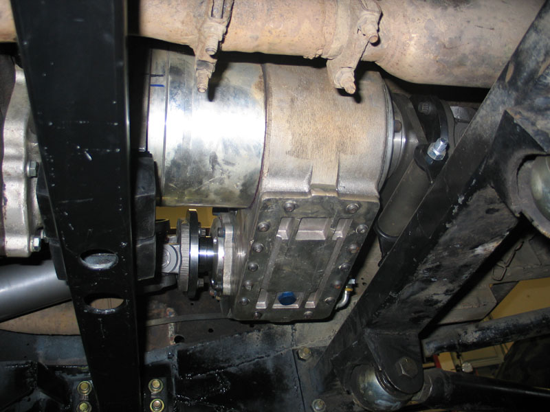
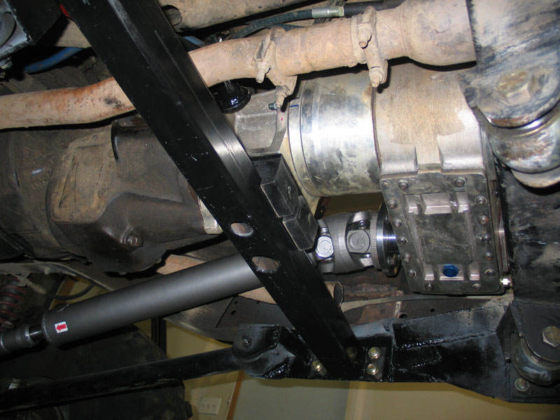
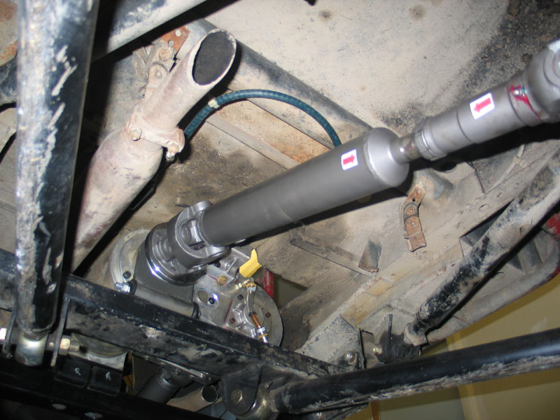
|
Sources: Advance Adapters (805) 238-7000 / (800) 350-2223 High Angle Driveline (530) 877-2875 Roark Fab Works (606) 286-0681 / Fax: (606)
286-0482 |
|