 |
BillaVista's Recovery Bible By Bill "BillaVista" Ansell |
IntroductionI decided to do this article because of the overwhelming number of incredibly dangerous things I see people do during vehicle recovery - in my own club, in magazines, and in pictures on the 'net. This is another one of those area's where there is an incredible amount of misinformation out there - and you know how I HATE misinformation. Common things I see people doing wrong all the time include: 1) Improper selection of gear, without understanding load ratings and safety margins 2) Improper use of gear - side loading shackles, improper use of wire-rope clips, hooking straps and cables to themselves without understanding the significant loss of load rating incurred, etc. 3) Unsafe practices - not keeping the area clear, handling wire rope with bare hands, etc. |
 |
This article will attempt to clear up all of these and more. It focuses on the proper selection and use of equipment for off-road vehicle recovery using an electric winch. It does not go into great detail about how to actually operate the winch or rig a winching operation - there are many other good sources for this information including: - The U.S. Army vehicle recovery manual, Warn's Guide to Winching, Magazine Articles, and other web pages. What it will focus on is all the other important info that isn't contained anywhere else, or at least not in any place or format readily accessible to recreational four wheelers. The information regarding rigging and equipment apply equally well if applying the force with a come-along, Hi-Lift jack or hand winch. So - without further ado.... HOISTING vs. WINCHINGHoisting refers to the vertical lifting of materials. This covers everything from Search and Rescue equipment/aircraft to enormous building cranes. There is an entire industry devoted to the safe and efficient practice of hoisting. Engineering is thorough and industry standard's are strict. In marked contrast, there are few, if any, industry standard for recreational vehicle winching (winching being the movement of objects in a horizontal, or mostly horizontal, plane), either in terms of safety, engineering and design practices, or whatever. As such, manufacturers can (and do) make all sorts of claims about product fitness and ratings based on no established standards. You will understand this thoroughly after having read this entire article. This little-known fact is another one of the primary reasons I am writing this article - so that consumers, users, and even bystanders can be better educated about what they are dealing with, the risks involved, and what some of the physics involved is...because there is no safety in simply relying on what's printed in a manufacturer's glossy catalogue. Often they don't tell the whole story, and even if they did - it wouldn't be based on industry, government, or accepted scientific standards. A lot of the information I have drawn upon in writing this article comes from the hoisting industry, simply because that is where the accurate and factual data is to be found. A complete list of references appears at the end of the article. Where there are marked differences between hoisting and winching in the subject I am discussing, I have attempted to alert the reader. The hoisting and lifting industry has strict safety standards, and for obvious reasons, as the vertical lifting of equipment and personnel is an inherently dangerous and risky business. This is the reason why I have recommended the adoption of as much of the hoisting industries safety practices, strict though they are - because I consider 4x4 recovery no less dangerous or risky than hoisting - especially when one considers how many people often crowd around the operation no matter how much you try to keep them clear, and in particular the woefully undersized wire ropes (cables) used on all recreational 4x4 recovery winches (much more on this later). Lethal BusinessIf you take nothing else away from this article, know this: EVERY time you mount an operation to recover a stuck 4x4, be it by winching, jacking, yank strap or whatever, you are playing with lethal force. The damage caused by equipment failure, or improper operation, can and WILL maim and kill people. NEVER underestimate it. There is a line in a movie that expresses it best. I forget to what it was the speaker was referring, but he may as well have been talking about any piece of recovery gear - particularly the winch and wire rope. He said "The minute you stop respecting this, it kills you." KEEP THAT IN MIND AT ALL TIMES. TERMS The first thing we need to get out of the way is a listing of the proper terms and definition regarding hoisting, winching, and rigging. Misuse of these terms can lead to great misunderstanding and unsafe practices. I shall endeavor to use the proper term as much as possible, but may occasionally slip up...the most likely case being referring to "wire rope" (proper term) as "winch cable" (common term). Pictures are included where they may be useful: |
|
bird cage --A colloquial term describing the appearance of wire rope forced into compression. The outer strands form a cage and, at times, displace the core. bleeding line --A condition caused when wire rope is overloaded, forcing the lubricant in the cable to be squeezed out and run excessively. |
|||||||||||||||||||||||||||||||||||||||||||||||||||||||||||||
 |
block --A term applied to a wire rope sheave (pulley) enclosed inside plates and fitted with some attachment such as a hook or shackle. | ||||||||||||||||||||||||||||||||||||||||||||||||||||||||||||
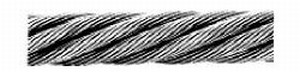
bright rope --Wire rope made of wires that are not coated with zinc or tin. cable --A term loosely applied to wire ropes, wire strand, and electrical conductors. Wire rope is the preferred term for winching, hoisting and rigging applications. |
|||||||||||||||||||||||||||||||||||||||||||||||||||||||||||||
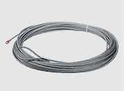 |
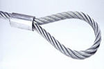
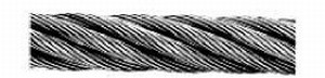
Wire Rope - often called "cable" | ||||||||||||||||||||||||||||||||||||||||||||||||||||||||||||
 |
clevis --A U-shaped fitting with holes in each end through which a pin or bolt is run. Also called a shackle. | ||||||||||||||||||||||||||||||||||||||||||||||||||||||||||||
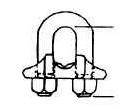 |
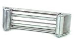
clip --Fitting for clamping two parts of wire rope. | ||||||||||||||||||||||||||||||||||||||||||||||||||||||||||||
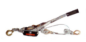 |
come-along --Lever-operated chain or wire rope devices designed for pulling, not lifting; also called pullers. Unlike hoists, the tension is held by a releasable ratchet. Much smaller and lighter than hoists of equal capacity, they are not intended nor allowed for lifting. | ||||||||||||||||||||||||||||||||||||||||||||||||||||||||||||
| D/d ratio -A term regarding wire rope. D = Diameter of curvature around which the rope is bent. d = diameter of rope. Example: With 0.5-inch-diameter rope passing over a 20-inch-diameter sheave, the D/d ratio is 40. The D/d ratio is a key factor in load-carrying ability and life span of a wire rope. | |||||||||||||||||||||||||||||||||||||||||||||||||||||||||||||
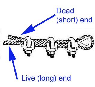 |
dead end --The point of fastening of one rope end in a running rope system, the other end being fastened at the rope drum. In other words, the short end. The other end is called the live end. | ||||||||||||||||||||||||||||||||||||||||||||||||||||||||||||
| design factor --The conservatism used in design calculations. As a function of design, this factor can be based upon the point of equipment failure, such as crane tipping, and brake stopping capacity, or based upon strength of materials, ultimate, nominal, or yield. Consensus standards express design factors as a ratio (for example: 5:1, 3:1, 3.5:1) or as a single number (for example: 5, 3, or 3.5, understood to mean to 1). Although a design factor is sometimes referred to as a safety factor, design factor is the preferred term. An inexperienced person may incorrectly assume this factor of design conservatism will make up for such conditions as shock loading, poor rigging, improper equipment selection, and overload conditions. | |||||||||||||||||||||||||||||||||||||||||||||||||||||||||||||
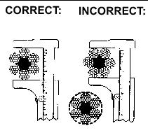 |
diameter (wire rope) --The diameter of wire rope is the diameter of the circle that will contain the rope. The diagram illustrates the concept by showing the correct and incorrect ways of measuring wire rope diameter. | ||||||||||||||||||||||||||||||||||||||||||||||||||||||||||||
Dog leg --Permanent short bend or kink in wire rope caused by improper use. dynamic loading --Loads introduced into the machine or its components by forces in motion. efficiency (wire rope) --Ratio of a wire rope's measured breaking strength and the aggregate strength of all individual wires tested separately, which is usually expressed as a percentage. The breaking strength of wire ropes seldom exceeds 90 percent of the aggregate strength of all the wires, the average being about 82.5 percent. elastic limit --Limit of stress above which a permanent deformation takes place within the material. This limit is approximately 55 to 65 percent of breaking strength of steel wire ropes. end termination --The treatment at the end or ends of a length of wire rope, which is usually made by forming an eye or attaching a fitting, designed to be the permanent end termination on the wire rope that connects it to the load. |
|||||||||||||||||||||||||||||||||||||||||||||||||||||||||||||
 |
eye or eye splice --A loop with or without a thimble formed in the end of a wire rope. The most common end termination. | ||||||||||||||||||||||||||||||||||||||||||||||||||||||||||||
fatigue --The phenomenon leading to fracture under repeated or fluctuating stresses having a maximum value less than the tensile strength of the material. fitting --Any accessory used as an attachment for wire rope. flange point --A point of contact between rope and drum flange where the rope changes layers. fleet angle --The maximum angle between a rope and the line perpendicular to the drum on which it winds. Flemish eye --A type or method of making a wire rope eye splice. Same as a Molly Hogan. grades, rope --Classification of wire rope by its breaking strength. In order of increasing breaking strengths: iron, traction, mild plow steel, plow steel, improved plow steel, and extra-improved plow steel. |
|||||||||||||||||||||||||||||||||||||||||||||||||||||||||||||
 |
hook -- Common fitting on the end of a wire rope, chain, or other rigging tackle. | ||||||||||||||||||||||||||||||||||||||||||||||||||||||||||||
 |
idler --Sheave or roller used to guide or support a rope. It is also used as a slang expression for an equaling sheave. The most commonly encountered in 4x4 winching would be the "rollers" of the typical roller fairlead. Roller fairleads consist of 4 idlers |
||||||||||||||||||||||||||||||||||||||||||||||||||||||||||||
kink --Permanent distortion of wires and strands resulting from sharp bends. load, rated --The maximum static load for which a winch, hoist, or crane is designed. It is a vertical load for crane’s and hoists, and a horizontal load for winches. See rated capacity. load rating --Rating in pounds established by the manufacturer. load, safe working (SWL) --The maximum load a piece of equipment (or tackle) can handle without exceeding the rated capacity (the rated capacity of the lowest capacity item used in the pull or lift). See load, rated. load, working --The external load, in pounds applied to the winch or hoist. The weight of load-attaching equipment is included as part of the working load (e.g., load blocks, hooks, shackles, and slings). NLGI Grade number --A grade number defining the consistency of grease in accordance with methods prescribed by the National Lubricating Grease Institute. nominal strength, wire rope --Nominal wire rope strengths as calculated by a standardized industry-accepted procedure. Minimum acceptance strength is 22% lower than nominal strength. (Re:Wire Rope Users Manual.) nondestructive examination (NDE) --A name applied to a variety of tests which make use of indirect means to locate material discontinuities (e.g., radiography, dye penetrant, magnetic particle, ultrasonics). pawl (dog)--A device for positively holding a member against motion in one or more directions. paying out --Adding slack to a line or relieving load on a line by letting (spooling) out rope. Also called spooling out or freespooling |
|||||||||||||||||||||||||||||||||||||||||||||||||||||||||||||
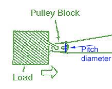 |
pitch diameter --The distance, measured through the center of a drum or sheave, from center to center of a rope passed about the periphery of the drum or sheave. | ||||||||||||||||||||||||||||||||||||||||||||||||||||||||||||
rated load (capacity)--The maximum load designated by the manufacturer for which a winch, hoist, rigging, or other device is designed and built. rated rope (line) pull --The manufacturer’s recommended load in pounds (kilograms) applied to the rope attached to the hoist drum. reeve -- To pass (as a rope) through a hole or opening, to fasten by passing through a hole or around something, to pass a rope through, to pass through a block or similar device rope --Refers to wire rope unless otherwise specified. rope drum --That part of a winch that consists of a rotating cylinder with side flanges on which rope is spooled in or out (wrapped). running line --A rope that moves over sheaves or drums. seize --To bind securely the end of a wire rope or strand with seizing wire or strand. seizing strand --Small strand, usually of seven wires, made of soft-annealed-iron wire. seizing wire --A soft-annealed-iron wire. serve --To cover the surface of a wire rope or strand with a wrapping of wire. |
|||||||||||||||||||||||||||||||||||||||||||||||||||||||||||||
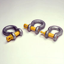 |
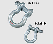
shackle --A type of clevis normally used for lifting. | ||||||||||||||||||||||||||||||||||||||||||||||||||||||||||||
| sheave --A wheel or pulley with a circumferential groove designed for a particular size of wire rope; used to change direction of a running rope. | |||||||||||||||||||||||||||||||||||||||||||||||||||||||||||||
|
slings --Wire ropes, chains, or synthetic fabric made into forms, with or without fittings, for handling loads. Note that the most common types in 4x4 recovery are "tree saver" straps and lengths of chain with hooks. These are technically "slings"
|
||||||||||||||||||||||||||||||||||||||||||||||||||||||||||||
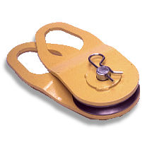 |
snatch block --A single- or double-sheave block arranged so one or both cheek plates can be opened, permitting the block to be reeved without having to use a free rope end; also called gate block. (The brand name SKOCUM is also used generically; thus, snatch blocks are also called skocum blocks.) | ||||||||||||||||||||||||||||||||||||||||||||||||||||||||||||
|
splicing --Interweaving of two ends of ropes to make a continuous or endless length without appreciably increasing the diameter. Also, making a loop or eye in the end or a rope by tucking the ends of the strands. | ||||||||||||||||||||||||||||||||||||||||||||||||||||||||||||
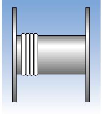 |
spooling (rope) --Winding of rope on a cylindrical drum in evenly spaced, uniform layers. Proper spooling of rope on the drum is tight and evenly spaced |
||||||||||||||||||||||||||||||||||||||||||||||||||||||||||||
strength margin --The ratio of structural failure load (or stress) to actual or permitted load (or stress). structural competence --The ability of the equipment and its components to support the stresses imposed by operating loads without the stresses exceeding specified limits. |
|||||||||||||||||||||||||||||||||||||||||||||||||||||||||||||
|
swaged fittings --Fittings in which wire rope is inserted and attached by a cold-forming method. The strongest type of end fitting, but not commonly seen in 4x4 winching. | ||||||||||||||||||||||||||||||||||||||||||||||||||||||||||||
| tackle --Those pieces of rigging such as slings, spreader bars, chokers shackles, thimbles, eyebolts, rings, or other handling fixtures used for attachment of the load to the crane or hoist. | |||||||||||||||||||||||||||||||||||||||||||||||||||||||||||||
|
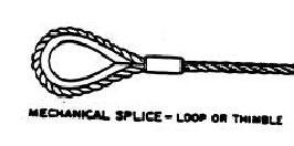
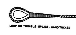
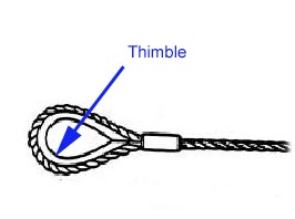
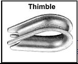
thimble --Grooved-metal fitting designed to prevent crushing or overstressing wire rope at the terminal end which is used to protect the eye of a wire rope or sling. | ||||||||||||||||||||||||||||||||||||||||||||||||||||||||||||
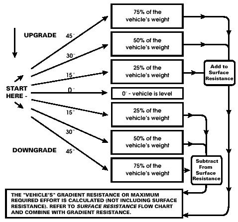
ultimate strength --The maximum conventional stress, tensile, compressive, or shear that a material can stand without failure. working load limit --WLL (see rated capacity). The Weakest Link:This is a very simple, but crucial, and yet almost universally unknown or ignored concept. It's the one most likely to get you hurt or killed, or wreck your rig. It is the one I shall harp on about most in my article. The concept is this: Every single piece of tackle used in a recovery operation, from tow hook to shackle to winch hook to wire rope end termination to the wire rope itself to the winch and to the winch mounting and structure of the vehicles themselves absolutely MUST be capable of SAFELY handling the loads that will be imposed. Let me say it again...EVERY PIECE. It's no good having a 12,000lb winch with a honking new 1/2" thick wire rope, if that wire rope terminates in an underrated hook, or even less obvious, has an improperly done end termination (very common - particularly the improper use of wire rope clips - more on this later). I see this all the time, and I believe some major manufacturers are not terribly good about informing the buyers and users of their products of this concept. A MAJOR contributor to the abuse of this concept is the huge lack of knowledge that exists regarding how maintenance (or lack thereof) or improper rigging (ever seen someone loop a winch cable around something then just slip the hook over itself?) DRASTICALLY effects the Safe Working Load (SWL) of the equipment. Sure everyone's read that you're not "supposed" to hook the winch cable back onto itself - but many, many people do. Why? Because they don't know what the real effect is, and often they have no real appreciation of the forces in play. Read on, dear friend, and I shall make it all perfectly clear (I hope!) Calculating the force of a recovery operation:This is a critical step in both the conduct of a winch recovery (because you need to be absolutely sure that EVERY single piece of equipment used in the task is strong enough and will not fail and thereby endanger life and limb), and in the selection/purchase and decision to use a piece of recovery equipment. It is a calculation where, quite frankly, the manufacturer's recommendations are woefully inadequate. Why? Simply because if they let you in on how large the forces really are, it would leave you realizing that they are unable to economically produce a winch of sufficient capacity in anything resembling a small, light, or economical enough package. They get away with it, because, as I said, there are virtually no regulations or standards governing the industry. I'm not saying all 4x4 winches are inadequate, dangerous, or useless. But I am saying that the forces involved are often much greater than the manufacturer's would have you believe, and you will be far more capable and SAFER if you approach your 4x4 recovery KNOWING THIS, and knowing the real numbers. Realize, that for reasons of practicality and economics, your 4x4 recovery equipment is almost certainly undersized.....you can still do the job, using the correct techniques, but you will be much SAFER if you keep this in mind. Enough of the pre-amble. Most, if not all, winch manufacturers will tell you to select a winch based on 1.5 times the gross vehicle weight. This often leads to less than satisfactory results for 2 reasons: 1) Most people are terrible at actually estimating the gross weight of their rig as it sits on the trail, full of gas, tools, equipment, food, camping gear, people, the dog...everything. Heck, in some cases the real figure can actually exceed the GVWR of the vehicle. Simple advice here - either err WAY on the heavy side, or get your rig weighed in trail trim. 2) More importantly, the "effective weight" of a "stuck" 4x4 is very often FAR more than 1.5 times the GVW. The following data on how to more accurately estimate the "effective weight", is taken from the world of professional heavy recovery - the guys that recover Tractor-trailers that have flipped on their side for instance, as well as U.S., Canadian, and UK Military recovery manuals. Once you have accurately estimated or measured the trucks loaded weight (LW) you can calculate the resistance to be overcome in any recovery situation (this is commonly known as the ROLLING resistance). There are 4 types of resistance that must be accounted for to accurately assess the resistance that must be overcome. These are surface resistance, damage resistance, mire (stuck) resistance and grade (slope) resistance. Calculate them all as follows: Surface resistanceA pull of 1/10 LW will cause a free wheeling truck to move on a hard, level surface. A pull of 1/3 LW will cause a free wheeling truck to move on a softer surface, such as grass or gravel, Damage resistance:A pull of 2/3 LW will be required to move if the wheels cannot rotate (as if the brakes were fully applied), the pull required to overcome the resistance (drag) the truck id 2/3 or 67% of the LW. Damage resistance includes surface resistance (i.e. you only use one or the other) Stuck (mire) resistance:A pull of 100% of LW will be required if the truck is stuck to a depth of the sidewall on the tires. A pull of 200% of LW will be required if the truck is stuck to the hubs. A pull of 300% of LW will be required if the truck is stuck to the frame.. Mire resistance includes damage resistance (i.e. you only use one or the other) Grade (slope) resistance:Upgrade (vehicle has to be recovered up a slope or grade) 15 degrees - add 25% of LW 30 degrees - add 50% of LW 45 degrees - add 75% of LW Vehicle recovery on level ground - no correction Downgrade (vehicle has to be recovered down a slope or grade) 15 degrees - subtract 25% of LW 30 degrees - subtract 50% of LW 45 degrees - subtract 75% of LW Final figure:Add surface or damage or mire resistance and grade resistance, and this is your final figure or rolling resistance. This is the amount of pull the winch must apply in order to recover the stuck vehicle. Example:My trail rig fully kitted out weighs in at 5000 lbs. I get stuck down a rock ravine that's about 45 degrees steep, and there are big rocks up to the frame hanging it up. Rolling resistance is 5000lbs x 3 + (5000 x 0.75) = 18,750 lbs. As you can see, this is significantly more than the 5000lbs x 1.5 - 7500lbs the manufacturers would have you believe. You may be wondering how one could ever possibly recover the vehicle in this example, given that the largest commercially available 4x4 recovery winch is 15000 lbs and that most are in the 8-9000lb range. The answer is by using multi-line rigging, which we shall explore in a moment. |
|||||||||||||||||||||||||||||||||||||||||||||||||||||||||||||
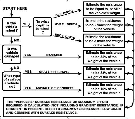 |
Here's a simple flowchart that provides the same info | ||||||||||||||||||||||||||||||||||||||||||||||||||||||||||||
 |
|||||||||||||||||||||||||||||||||||||||||||||||||||||||||||||
All about WIRE ROPEThe least understood, most abused, most critical part of your winch - the wire rope (often called the winch cable, or just cable). As you read the information below - remember this. Wire rope is a machine - a complicated machine made of many moving parts. Learn all you can about it, how to safely handle, use, and maintain it, and of course, remember The minute you stop respecting this, it kills you! GENERAL INFORMATION |
|||||||||||||||||||||||||||||||||||||||||||||||||||||||||||||
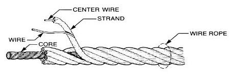 |
COMPONENTS:Wire rope consists of three basic components. 1. Wires. 2. Strands, formed by wires, laid helically around a core. 3. Core, or center. |
||||||||||||||||||||||||||||||||||||||||||||||||||||||||||||
MATERIAL:Steel grades in wide use today are IPS (improved plow steel), EIPS (extra improved plow steel), sometimes also referred to as XIPS, XIP, or EIP, as well as EEIPS (extra, extra improved plow steel). CORE:Its function is to provide proper support for the strands under normal conditions. Three types of core (or center) are commonly used. 1. Fiber Core (F.C.), usually polypropylene (P.C.), sometimes hemp (H.C.) and sisal. 2. Independent Wire Rope Core (IWRC) 3. Wire Strand Core (WSC) IWRC and WSC are sometimes referred to as steel wire core or steel center. Steel CoreSteel core consists of strands of wire wrapped around a steel core. Steel core is not as susceptible to crushing as fiber core. Fiber core, on the other hand, is composed of wire wrapped around a fiber or man-made center. An independent wire rope core, (IWRC), adds strength (7½% min.) and provides resistance to crushing. This style of wire rope best serves a car carriers winch. A 6x19 wire is more durable than the more flexible 6x37 wire. Fiber CoreThese are composed of manila, jute, sisal or more recently, man-made polypropylene, offering better resistance to rotting, drying out and other forms of deterioration. Fiber core "cushions" the steel strands during operation. As the core is usually impregnated with lubricant before manufacture, it continues to act as an internal lubricator during the operation of the rope. Fiber core is less violent than steel core as it recoils after failure (breaking). CONSTRUCTION:Expressed in numbers of strands x number of wires. 6 x 25 indicates that the wire rope consists of 6 strands, which in turn have 25 individual wires. Constructions are grouped into classes: 6 x 7 Class: Containing 6 strands that are made up of 3 through 14 wires, of which no more than 9 are outside wires. 8 x 19 and 19 x 7 class wire ropes have rotation-resistant properties, excluding elevator ropes. The constructions listed above are just some of the more popular constructions. Other common constructions include: 7 x 7, 7 x 19: Galvanized cable. Sometimes referred to as "aircraft cable" but not intended for aircraft use. 1 x 7, 1 x 19: Strand 7 x 7 x 7, 7 x 7 x 19: Cable Laid Many others exist, some for highly specialized applications only. Note that any class denotes the nominal number of wires in each strand. The actual number of wires may be different. For example 6 x 36 class: strands most commonly consist of 36 wires, or 31, or 41. FINISH:Wire rope is either sold as "bright" (or "black") - meaning uncoated, or galvanized for better corrosion resistance. "Drawn Galvanized" wire has the same strength as bright wire, but wire, "galvanized at finished size" is usually 10% lower in strength. Plastic coated wire rope is also available, usually galvanized or stainless steel cable. The most common plastic coatings are vinyl or nylon in either clear or white, although other materials and colors are available. These coatings do not add strength to the wire rope itself. PREFORMING:A manufacturing process wherein the strands and their wires are permanently formed - during fabrication - to the helical shape that they will ultimately assume in the finished wire rope. Proper pre forming prevents the strands and wires from unlaying during normal use. The vast majority of wire rope sold today is preformed. LAY:Indicates how the wires have been laid to form strands and how the strands have been laid around the core. A right regular lay rope (RRL; the most common) has its strands laid right on the rope - similar to threading a right-hand threaded bolt. Regular means that the direction of the wire lay in the strand is opposite to the direction of the strand lay in the rope. (The wires in regular lay rope appear to be in line with the axis of the rope). |
|||||||||||||||||||||||||||||||||||||||||||||||||||||||||||||
 |
Right Regular Lay (RRL) | ||||||||||||||||||||||||||||||||||||||||||||||||||||||||||||
 |
Right Lang Lay | ||||||||||||||||||||||||||||||||||||||||||||||||||||||||||||
 |
Left Regular Lay | ||||||||||||||||||||||||||||||||||||||||||||||||||||||||||||
 |
Left Lang Lay | ||||||||||||||||||||||||||||||||||||||||||||||||||||||||||||
CAUTION: When combining separate ropes for a recovery operation, always use ropes of the same lay pattern. Different lays can increase rotation at connection points decreasing rope efficiency. BREAKING IN NEW WIRE ROPESince wire rope is a machine with many moving parts, it requires careful installation and breaking in procedures for maximum safety and long service life. After proper installation, allow the wire rope to run through a cycle of operation at a very low speed. Keep a close watch on the wire rope, its attachments and any working parts such as sheaves, drums, rollers, etc. to make certain that the wire rope runs freely. If no problems appear at this stage, run the wire rope through several cycles of operation under light load at reduced speed. This procedure allows the component parts of the new rope to make a gradual adjustment to the actual operating conditions. WIRE ROPE EFFICIENCYWire rope will develop 100% efficiency, that is, break at or above minimum acceptance strength (not less than 2.5% below nominal breaking strength) ONLY under controlled laboratory conditions. Once fittings such as sleeves, clips, sockets, etc. are attached and/or the wire rope passes over a curved surface such as sheaves, pins, etc. its strength is decreased. In the case of wire rope passing over a curved surface this decrease in strength depends on the severity of the bend. In the case of wire rope fittings, the decrease in wire rope strength will depend on the type of fittings used. The wire rope efficiency usually ranges from 70% - 100%. Note, that hand spliced wire rope, while not using any fittings, has less efficiency than properly flemished and swaged wire rope. ELASTIC PROPERTIES OF WIRE ROPEWire rope is an elastic member; it stretches or elongates under load. This elongation can be permanent or recoverable. The extent of elongation will depend on the wire rope used and the design factor chosen. While it may be acceptable for many wire rope uses to neglect its elastic properties, they are of critical importance for 4x4 vehicle recovery uses, as a stretched-under-load wire rope stores enormous potential energy that can be explosively released (converted to kinetic energy) when the rope or a fitting fails. The result of this can be severe injury or death caused by a scything cable or high velocity projectile that was once part of the recovery rigging. Pre-stretching or breaking-in wire rope will only remove some of the constructional stretch and will not totally eliminate elongation under load. WINDING WIRE ROPE ON DRUMSInstallation of wire rope on a plain or grooved drum requires a great deal of care. Make certain the wire rope is properly attached to the drum. Keep adequate tension on the wire rope as it is wound onto the drum. Guide each wrap as close to the preceding wrap as possible, or follow the groove in case of a grooved drum. For a better understanding of wire rope I highly recommend the Wire Rope Users Manual by the Wire Rope Technical Board. RATED CAPACITYRated capacity is the load which a new wire rope may handle under given operating conditions and at assumed design factor. A design factor of 5 is chosen most frequently for hoisting with wire rope. (Operating loads not to exceed 20% of Nominal Breaking Strength.) Operating loads may have to be reduced when life, limb or valuable property are at risk or other than new rope is used. A design factor of 10 is usually chosen when wire rope is used to carry personnel. (Operating loads not to exceed 10% of catalog Breaking Strength.) Wire Rope StrengthIn order to know the strength of your wire rope, you need to know it's class and material. For example, is it 6x19 Improved Plow Steel, or is it 7x19 Galvanized (aircraft) cable? Most winches sold for the 4x4 market come with 5/16" or 3/8" diameter 7x19 galvanized wire rope. Below is a table listing the specifications for 7x19 Galvanized - the most common type supplied with and replaced on 4x4 winches. Also shown is 7x19 Type 304 Stainless Steel. It's easy to see the potential for problems when taking into account the factors described above. If your Warn HS9500 winch came with 5/16" wire rope, it has a nominal breaking strength of approximately 9,800 lbs. Remember, that's at 100% efficiency under laboratory conditions ONLY. Add some fittings, wind it on a drum, and use it a couple of times and the breaking strength can be way below the force the winch can generate...which can be very dangerous if not understood and respected. Also, remember that's BREAKING STRENGTH, not Safe Working Load with a design factor. Just for illustrative purposes, if one were to apply hoisting industry guidelines and use a design factor of 5, that brand new 5/16" rope would have a safe working load of 9,800 / 5 = 1960lbs under ideal conditions. If the cable was well used, not particularly well maintained, and had a less than optimal end termination (sound like any you've seen?) that could drop it's efficiency to 70% or less, so keeping the same design factor (although admittedly the purpose of the design factor is to account for such losses in efficiency) would mean a SWL of 1960 x 70% = 1372 lbs !!!!!! Add the fact that you totally stuck rig could easily have a rolling resistance of up to 10-15,000 lbs, is it any wonder these things fail and people get hurt! Bottom line - understand your gear and it's limitations, maintain it well, replace when worn, and treat it as lethal, and you're much more likely to have an effective and SAFE winching experience. 7 X 19 GALVANIZED CABLE
7 x 19 STAINLESS STEEL CABLE, TYPE 304
* Listed for comparison only. Actual operating loads may vary, but should never exceed recommended design factor or 20% of catalog Breaking Strength. USING WIRE ROPEAttachments must have at least the same Working Load Limit as the wire rope usedClips, sockets, thimbles, sleeves, hooks, links, shackles, sheaves, blocks, etc. must match in size, material and strength to provide adequate safety protection. Proper installation is crucial for maximum efficiency and safety Avoid shock loadsAvoid impacting, jerking or swinging of load. Working Load limit will not apply in these circumstances because a shock load is generally significantly greater than the static load Wire Rope LubricationThe lubrication ropes receive during manufacture is adequate only for initial storage and the early stages of the rope’s service life. A winch's wire rope should be maintained in a well-lubricated condition. It is important that lubricant be applied as part of the maintenance program. The lubricant must be compatible with the original lubricant, so the rope manufacturer should be consulted. The lubricant applied should be of the type that does not hinder visual inspection. The surface of some ropes may become covered with dirt, rock dust or other material during their operation. This can prevent field-applied lubricants from properly penetrating into the rope, so it's a good practice to clean these ropes before you lubricate them. Before Initial Load CycleAfter wire rope replacement, and before the initial load cycle, verify the following conditions. 1. The rope attachment points to the hoist drum and dead end (if applicable) are properly installed. 2. Fasteners are properly torqued. 3. Reeving is in accordance with the manufacturer's recommendations. Initial CycleAfter rope replacement and before returning the equipment to service, it is recommended that the winch be cycled from maximum rope out to fully spooled in eight to ten times with 10 percent to 20 percent of rated load. A new rope will stretch and unlay slightly, after initial cycling as described, the wire rope should be carefully re-spooled so as to allow flat, even wraps on the drum. A rope should not be stored on the drum in a twisted or kinked fashion. After the initial load cycle has been completed, you should verify that the fasteners on drum and/or dead end have been retorqued. Inspect Wire Rope Regularly Check the general condition of the wire rope. Also, look for localized damage and wear, especially at wire rope attachments. Inspect all parts that come in contact with the wire rope. Poor performance of wire rope can often be traced back to worn or wrong-sized sheaves, drums, rollers, etc. Look for kinks, broken wires, abrasions, lack of lubrication, rust damage, crushing, reduction of diameter, stretch or other obvious damage. If any of these conditions exists or if there is any other apparent damage to the wire rope, retire the wire rope according to the instructions below. Daily InspectionEvery day you intend or may use the winch, a visual observation of the wire rope should be made. These visual observations should be concerned with discovering gross damage that may be an immediate hazard, such as the following: 1. Rope distortion such as kinking, crushing, unstranding, birdcaging, main strand displacement, or core protrusion 2. Corrosion 3. Broken or cut strands. Monthly InspectionAt the start of the wheeling season, and monthly during the season you should inspect the wire rope for: 1. Reduction of rope diameter below nominal diameter as a result of loss of core support, internal or external corrosion, or wear of outside wires 2. A number of broken outside wires and the degree of distribution or concentration of such broken wires 3. Worn outside wires 4. Corroded or broken wires at end connections 5. Corroded, cracked, bent, worn, or improperly applied end connections 6. Severe kinking, crushing, cutting, or unstranding. Wire Rope Replacement CriteriaThe following criteria determine when a wire rope is no longer acceptable for service: 1. 12 randomly distributed broken wires in one lay or four broken wires in one strand in one lay (A rope lay is that length of rope in which one strand makes one complete revolution about the core) 2. One outer wire broken at the contact point with the core of the rope, which has worked its way out of the rope structure and protrudes or loops out from the rope structure 3. Wear of one-third the original diameter of outside individual wires 4. Kinking, crushing, birdcaging, or any other damage resulting in distortion of the rope structure 5. Evidence of heat damage from any cause 6. Reduction from nominal diameter greater than those listed in the following:
Destroy, rather than discard, wire rope to be retiredWire rope that is not destroyed might be used again by someone not aware of the hazard associated with that use. Destroying wire rope is best done by cutting it up into short pieces. How to select a rope for winching All wire ropes feature design characteristic trade-offs. In most cases, a wire rope cannot increase both fatigue resistance and abrasion resistance. For example, when you increase fatigue resistance by selecting a rope with more outer wires, the rope will have less abrasion resistance because of its greater number of smaller outer wires. More on use and care of Wire Rope 1. Wire rope WILL FAIL IF WORN OUT, OVERLOADED, MISUSED, DAMAGED, or IMPROPERLY MAINTAINED. (NOTE that with the wire ropes supplied on almost, if not, every recreational 4x4 winch the design factor is non-existent or negligible. This is the industry's "dirty little secret" and if not understood and accounted for - could get you hurt. This fact, in my mind, is the single biggest and best argument for using synthetic winch rope, and what makes it worth every penny of it's admittedly high price.) How much rope will fit on a winch? |
|||||||||||||||||||||||||||||||||||||||||||||||||||||||||||||
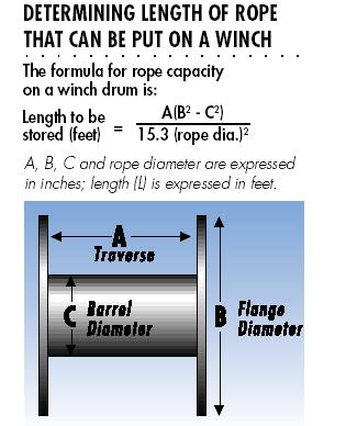 |
This diagram shows the equation used to calculate how much wire rope will fit on a winch drum. | ||||||||||||||||||||||||||||||||||||||||||||||||||||||||||||
End Terminations:It is critical that the proper end-termination be used on your winch rope. Not only that, but it is critical to understand the effect the type of end termination you use has on the efficiency (strength) of your wire rope. Note that the values differ for wire rope core and fibre core ropes. Note the relatively low value of 80% on the very commonly seen wire rope clips. Imagine the 5/16 7/19 galvanized wire rope on your 9500lb winch. Brand new, under ideal conditions, it's nominal breaking strength is 9800lbs (NO design factor). Put your hook on with wire rope clips, and even if you do it perfectly, that figure drops to 9800x80%=7840lbs....SCARY!!!
|
|||||||||||||||||||||||||||||||||||||||||||||||||||||||||||||
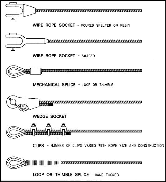 |
Pics of the various types of end terminations. | ||||||||||||||||||||||||||||||||||||||||||||||||||||||||||||
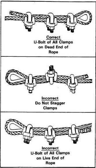
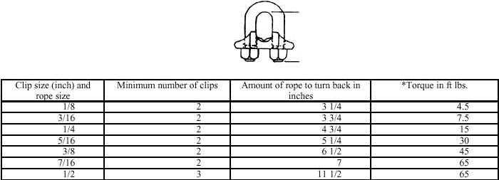
Using Wire Rope ClipsIf you must use wire rope clips as the end termination of your winch rope, understand the effect on strength (reduces 20%), and it is CRITICAL you use them properly as shown below: |
|||||||||||||||||||||||||||||||||||||||||||||||||||||||||||||
 |
|||||||||||||||||||||||||||||||||||||||||||||||||||||||||||||
 |
|||||||||||||||||||||||||||||||||||||||||||||||||||||||||||||
Requirements and guidelines for wire rope clamps are as follows:1. Clamps (also called clips) shall meet or exceed the requirements of Federal Specification FF-C-450, "Clamps, Wire Rope." 2. Clamps shall be legibly and permanently marked with size and the manufacturer's identifying mark. Inspection criteria for wire rope clamps follow: 1. Before use, clamps shall be visually inspected for damage, corrosion, wear, and cracks. 2. Verify that the clamp components are marked properly. 3. Ensure that the assembled clamp contains the same size, type, and class parts. Fittings:Now you know all about wire rope strength, working load limits, design factors, and the magnitude of the forces involved, it's important to examine some of the other "fittings" or pieces of tackle commonly employed in 4x4 recovery winching. It is worth repeating, any piece of gear you use ABSOLUTELY must have a WLL that is up to the task. The entire operation is only as strong as it's weakest link - don't be one of those people improperly side-loading a shackle or using a puny, under-rated hook on your winch. Hooks |
|||||||||||||||||||||||||||||||||||||||||||||||||||||||||||||
|
Some rigging hooks (e.g., grab hooks and sorting hooks) are designed to carry the load near the point as well as in the bowl or saddle of the hook. Maximum safe working loads normally apply only when the load is in the bowl or saddle. Rigging hooks shall be used within the limits specified by the manufacturer. Forged alloy steel hooks generally make the best rigging hooks. The manufacturer's identification shall be forged or die-stamped on the hook. Safe working loads or Working load limits for rigging hooks shall be equal to or exceed the rating of the chain, wire rope, or other suspension member to which it is attached. Where this is not feasible, special precautions shall be taken to ensure that the rated load limit of the hook is not exceeded. Welding on hooks, except by the hook manufacturer, is not allowed. Never repair, alter, rework, or reshape a hook by welding, heating, burning, or bending. | ||||||||||||||||||||||||||||||||||||||||||||||||||||||||||||
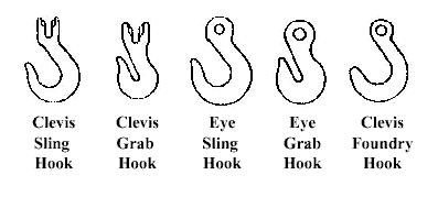
Requirements and guidelines for rigging hooks are as follows:Rigging hooks shall meet or exceed the requirements of ANSI/ASME B30.10, Hooks, Chapter 10-2, "Hooks, Miscellaneous." The SWL for a hook used in the manner for which it is intended shall be equal to or exceed the rated load of the chain, wire rope, or other suspension member to which it is attached. The designated SWL applies only when the load is applied in the bowl or saddle of the hook. The manufacturer's identification shall be forged or die-stamped on a low-stress and non-wearing area of the hook. There are many types of hooks available - some good, some not-so-good. Most use some type of Sling Hook on the winch wire rope - either an eye sling hook or clevis sling hook is acceptable, providing they are appropriately rated. Regardless of the hook used, it should have a throat latch that ridges the throat opening of the hook for the purpose of retaining slings, chains, or similar parts under slack conditions. Note that the latch is not intended to support the load. Most winches are supplied from the manufacturer with a clevis sling hook that I believe is not a particularly good hook, and should be thought of as the absolute minimum acceptable. Manufacturers cut corners (and costs) here in my opinion. Much better options are available, and should be used. In order of decreasing preference (i.e. best first): |
|||||||||||||||||||||||||||||||||||||||||||||||||||||||||||||
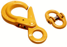 |
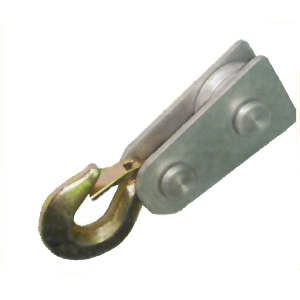
Positive locking hooks. These are the best hooks in my opinion, as it is virtually impossible for the fitting or sling to which the hook is attached to slip out either when it is loose or under tension. Opening and closing the hook requires thumb-activation of a small locking tab (visible on the left of the yellow hook). | ||||||||||||||||||||||||||||||||||||||||||||||||||||||||||||
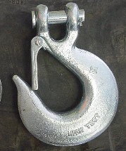 |
Throat latch clevis sling hook. | ||||||||||||||||||||||||||||||||||||||||||||||||||||||||||||
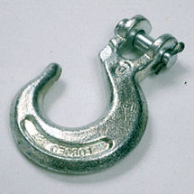 |
Stock clevis sling hook of type often supplied with winch. | ||||||||||||||||||||||||||||||||||||||||||||||||||||||||||||
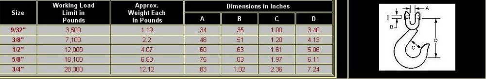
Hook Inspection:Regardless of the type of hook, as with all other recovery gear, an inspection program is required for the life of the equipment and safety of you and those around you during recovery. Hook visual inspection should be conducted daily (before use) to identify the following: a. Cracks, nicks, gouges Weekly to Monthly inspection should consist of checking for: a. Distortion, such as bending, twisting, or increased throat opening Quarterly inspection should consist of checking for: a. Deformation. Any bending or twisting exceeding 10 degrees from the plane of the unbent hook. If any of these conditions are found, the hook should be retired and replaced. Hook Specs:Here are the specs for Grade 80 Clevis sling hooks
ShacklesOne of the most useful, but also most often misused/abused pieces of recovery gear is the common clevis or shackle. Common errors include: - use of unmarked/unrated shackles - often from cheap off-shore sources - use of undersize or improperly rated shackles - improper rigging The following should set things straight and allow you to safely and properly make use of the venerable shackle. Shackle specifications:For shackles 3/16 to 2 3/4 inches, the specifications are derived from Federal Specification RR-C-271, “Chains and Attachments, Welded and Weldless.” |
|||||||||||||||||||||||||||||||||||||||||||||||||||||||||||||
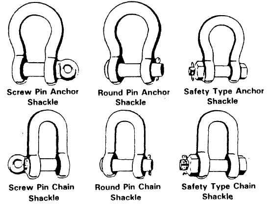 |
Shackles are manufactured in two configurations for use in rigging: anchor shackle and chain shackle. Both are available with screw pins, round pins, or safety bolts. | ||||||||||||||||||||||||||||||||||||||||||||||||||||||||||||
Shackles are sized by the diameter of steel in the bow section rather than the pin size. Design Factors:Shackles manufactured in accordance with RR-C-271 and MIL-S-24214 have a minimum design factor of 5. Shackles manufactured to the requirements of ASTM A148M have a minimum design factor of 4. Each shackle body shall be permanently and legibly marked by the manufacturer. Marking will be raised or stamped letters on the side of the shackle bow with an identifying manufacturer’s name or trademark, shackle size, and safe working load (SWL). Inspection: Before each use, shackles should be inspected to the following criteria. Operating practices and guidelines: |
|||||||||||||||||||||||||||||||||||||||||||||||||||||||||||||
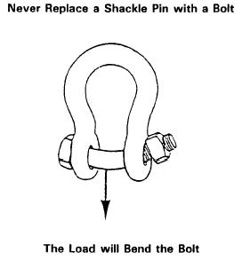 |
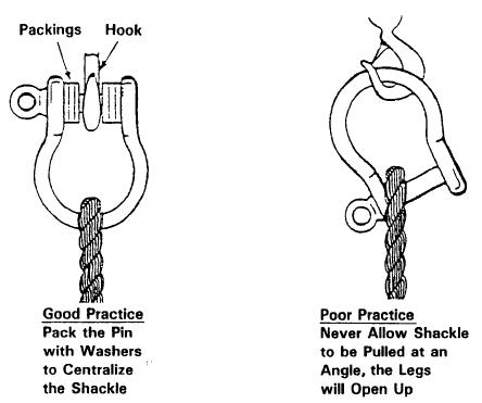
1. The shackle pin shall never be replaced with a bolt; only a properly fitted pin shall be used. Bolts are not intended to take the load that is normally applied to the pin. 2. Shackles shall not be used if the pin cannot be completely seated. |
||||||||||||||||||||||||||||||||||||||||||||||||||||||||||||
|
3. Shackles shall never be pulled at an angle because the capacity will be tremendously reduced. Centralize whatever is being hoisted on the pin by suitable washers or spacers. | ||||||||||||||||||||||||||||||||||||||||||||||||||||||||||||
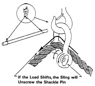 |
4. Screw pin shackles shall not be used if the pin can roll under load and unscrew. | ||||||||||||||||||||||||||||||||||||||||||||||||||||||||||||
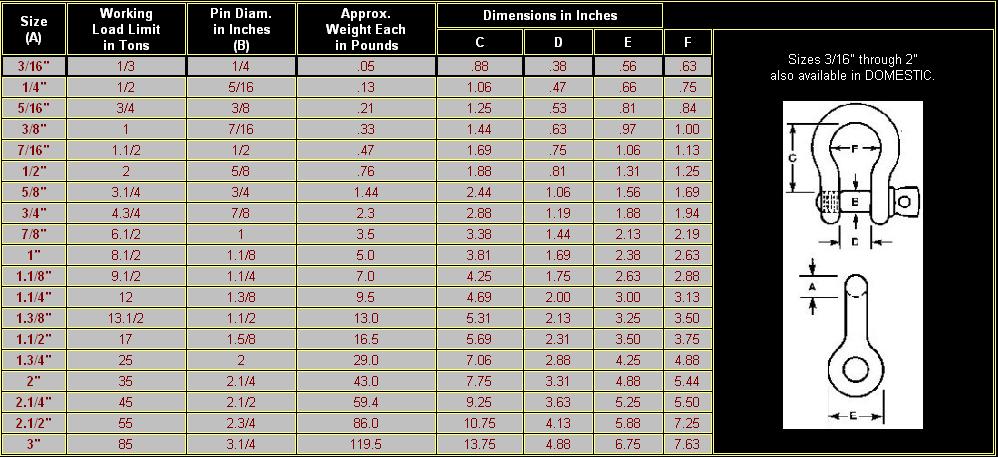
Specs:Here are the specs for galvanized screw pin anchor shackles:
SlingsWhat is a sling and why should you care? A sling is the term the hoisting industry uses for a device that attaches between the load hook on a crane or hoist, and the actual load. There is a great deal to know about the safe use of slings, as the way in which the are rigged can have a dramatic effect on their strength. |
|||||||||||||||||||||||||||||||||||||||||||||||||||||||||||||
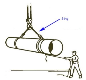 |
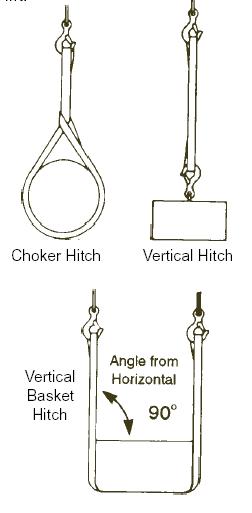
This picture shows a typical sling: | ||||||||||||||||||||||||||||||||||||||||||||||||||||||||||||
| It doesn't take a lot of imagination, looking at the above picture, to see that a tree-saver strap is a sling, although it is used horizontally rather than vertically. Depending on how it is rigged, it is usually a choker hitch or horizontal basket hitch. In both cases, the angle from the anchor to the rig winching is very important as it effects the rating / efficiency of the sling. Also, a length of chain with hooks on the end is also technically a "single leg sling". The following pics show some typical types of slings. Again, in our use, the loads will be applied horizontally (or mostly horizontally) rather than vertically, but it is easy to see that different types of slings are often used in 4x4 recovery or using a 4x4 winch to move objects. | |||||||||||||||||||||||||||||||||||||||||||||||||||||||||||||
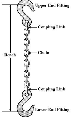 |
Slings can be of varying construction, from wire rope, webbing, and chain to synthetic materials and wire or chain mesh. The most common encountered on the trail are webbing (tree saver strap) and chain. Detailed information on Synthetic Web Slings (recovery straps and tree savers, for example) below in the "towing and yanking" section. Chain single-leg sling |
||||||||||||||||||||||||||||||||||||||||||||||||||||||||||||
 |
When a sling is used in a choker hitch, the angle formed in the rope body as it passed through the choking eye (the choke angle) should be 120° or greater. In the diagram to the left, imagine the "load" is a tree or rock being used as an anchor point for the pull, or an object, tree, rock etc. that is being winched out of the way. | ||||||||||||||||||||||||||||||||||||||||||||||||||||||||||||
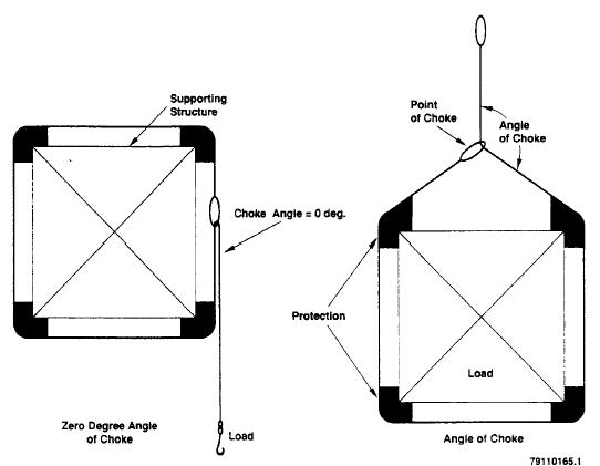 |
For choke angles of less than 120°, the rated load shall be reduced as shown below:
|
||||||||||||||||||||||||||||||||||||||||||||||||||||||||||||
Any good tree-saver strap (sling) will be marked with Safe Working Loads (or Working Load Limits) listed for Vertical (or straight), basket, and choker. Be sure you are using a sufficiently rated piece of gear for the way on which you rig it. Choker ratings are significantly less that straight or basket. For example, on my own professionally made (hoisting industry) web slings (tree savers) 3" wide, 2 ply nylon are marked: Vertical 8,400 lbs Basket 16,800 lbs Choker 6,300 lbs As you can see, with my 8000lb Warn 8274, it is perfectly safe as a basket hitch, marginal as a straight sling, and not a good idea to use it in a choker hitch configuration. There is a great deal more to know about safe and effective use of slings. rather than repeat it here, you can read it here: U.S. Department of Energy's Hoisting and Rigging Manual ch9 - SLINGS - PDF file ChainAnother piece of gear you see on the trail all the time. It can be extremely useful and versatile, but is very often misused. If chain is going to be used anywhere in a recovery operation (and personally, I think this should be avoided if possible, because of the hazards, and most importantly because often grade, strength, and condition are difficult to verify), it should only be Grade 80 Alloy Steel chain of a size suitable for the task. Chain for alloy steel chain slings shall conform to the requirements of ASTM A391/A 391M, Standard Specification for Grade 80 Alloy Steel Chain. Rated Requirements for attachments to alloy steel chain slings follow: Inspection:Chain and attachments should display no wear, nicks, cracks, breaks, gouges, stretch, bends, weld splatter, discoloration from excessive temperature, or excessive throat opening of hooks. Chain links and attachments shall hinge freely with adjacent links. Latches on hooks, if present, should hinge freely and seat properly without evidence of permanent distortion. Operating Practices: Operating practices and guidelines for the use of alloy steel chains are as follows: Specs: |
|||||||||||||||||||||||||||||||||||||||||||||||||||||||||||||
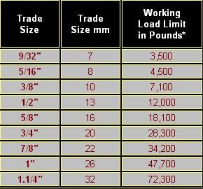 |
Here are the specs for Grade 80 Alloy Steel chain: | ||||||||||||||||||||||||||||||||||||||||||||||||||||||||||||
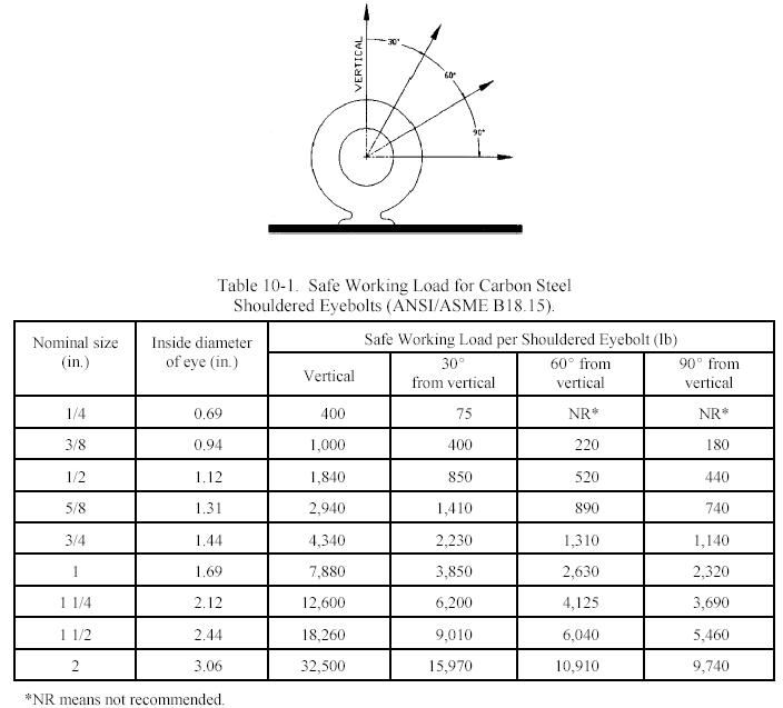
Eye BoltsOnly shouldered eyebolts should be used for rigging hardware. Carbon Steel Eyebolts shall have the manufacturer's name or identification mark forged in raised characters on the surface of the eyebolt. Alloy Steel Eyebolts shall have the symbol “A” (denoting alloy steel) and the manufacturer's name or identification mark forged in raised characters on the surface of the eyebolt. Eyebolts should have a minimum design factor of 5, based on ultimate strength. Carbon steel eyebolts shall be made of forged carbon steel. Alloy steel eyebolts are forged, quenched, and tempered with improved toughness properties, intended primarily for low temperature applications. Nuts, washers, and drilled plates shall not be used or assembled to make shouldered eyebolts. Wire type and/or welded eyebolts should not be used in recovery operations. Shoulders should seat uniformly and snugly against the surface on which they bear. Inspection:Criteria for eyebolts are as follows: Operating Procedures:1. To attain the rated capacity for threaded hole applications, minimum thread shank length of engagement for steel eye bolts should be at least 1.5 thread diameters, and preferably 2 or more. 2. To attain the rated capacity for untapped through-hole applications, use shouldered eyebolts, steel washer, and a nut with required thread engagement. 3. The size of the hole shall be checked for the proper size of eyebolt before installation. The condition of the threads in the hole shall be checked to ensure that the eyebolt will secure and that the shoulder can be brought to a snug and uniformly engaged seat. 4. When installed, the shoulder of the eyebolt must be flush with the surface . When eyebolts cannot be properly seated and aligned with each other, a steel washer or spacer not to exceed one thread pitch may be required to put the plane of the eye in the direction of the load when the shoulder is seated. Proper thread engagement must be maintained. Use a washer with approximately the same diameter as the eyebolt shoulder and the smallest inside diameter that will fit the eyebolt shank |
|||||||||||||||||||||||||||||||||||||||||||||||||||||||||||||
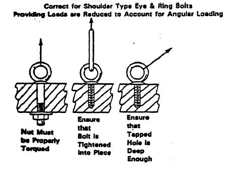 |
5. Angular loading of eyebolts should be avoided. Angular loading occurs in any pull in which the pulling force is applied at an angle to the centerline of the eyebolt shank. 6. Shouldered eyebolts may be used for angular pulling, providing the limiting conditions in the table below are considered. |
||||||||||||||||||||||||||||||||||||||||||||||||||||||||||||
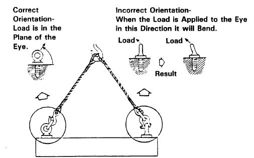 |
7. To keep bending forces on the eyebolt to a minimum, the load shall always be applied in the plane of the eye, never in the other direction. 8. If the hook will not go completely into the eyebolt, use a shackle to avoid loading the hook tip. 9. Slings shall not be reeved through an eyebolt or reeved through a pair of eyebolts. Only one leg of the sling should be attached to each eyebolt. |
||||||||||||||||||||||||||||||||||||||||||||||||||||||||||||
Specs:
This table taken from the vertical hoisting documentation. For 4x4 recovery use - substitute the word "straight line" for vertical. That is to say - if you are pulling on an eyebolt at an angle to the centerline of the eyebolt shank, reduce the SWL of the eyebolt as above, and re-rig the pull if required. Capacities shown in this table are for carbon steel ASTM A-489 eyebolts at temperatures between 30 °F (-1 °C) and 275 °F (135 °C). Carbon steel is subject to failure from shock loading at temperatures below 30 °F and loses strength at temperatures above 275 °F. Eyebolts from selected manufacturers may have higher SWL. Regardless of SWL, ensure that eyebolts have a design factor of 5. Blocks (sheave, pulley, snatch block) |
|||||||||||||||||||||||||||||||||||||||||||||||||||||||||||||
 |
The following data is critically important to us, as all of the devices shown are examples of sheaves and pulley's that we use. | ||||||||||||||||||||||||||||||||||||||||||||||||||||||||||||
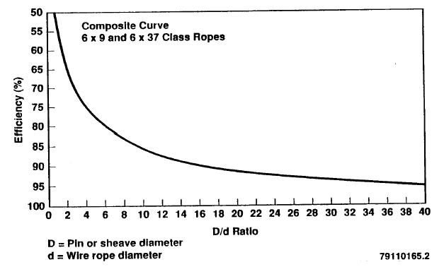 |
The strength reduction (efficiency) of a recovery rigging setup using any kind of block or sheave is based on the D/d ratio, where D is the pin or sheave diameter, and d is the rope diameter. For example, a rope bent around a pin of equal diameter will have a D/d ratio of 1. The efficiency will be 50 percent. The rope will have only 50 percent of the nominal strength attributed to it. This factor applies to your roller fairlead too, as it is a sheave. | ||||||||||||||||||||||||||||||||||||||||||||||||||||||||||||
Sheave (pulley) diameters and rope bending diameters: |
|||||||||||||||||||||||||||||||||||||||||||||||||||||||||||||
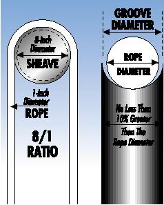 |
To assure maximum efficiency and safety, sheaves for wire ropes should be no less than eight times the rope diameter. The sheave groove diameter should be no less than ten percent greater than the rope diameter. The sheave groove should be round in shape. Sheaves with "V" shaped grooves should be avoided, as they tend to pinch and damage the rope through excessive friction and crushing of the rope fibers. Sheave surfaces should be kept smooth and free of burrs and gouges. Bearings should be maintained to ensure smooth rotation of sheaves. | ||||||||||||||||||||||||||||||||||||||||||||||||||||||||||||
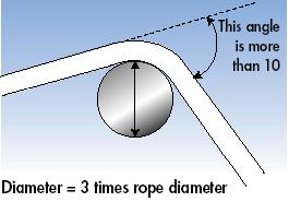 |
Any sharp bend in a rope under load decreases its strength substantially and may cause premature damage or failure. Where a rope bends more than ten degrees in bending across any surface, the diameter of that surface should not be less than three times the diameter of the rope. Stated another way, the diameter of the surface should be at least three times the rope diameter. A four-to-one ratio (or larger) would be better yet because the durability of the rope increases substantially as the diameter of the surface over which it is worked increases. This factor applies to your roller fairlead too, as it is a sheave. | ||||||||||||||||||||||||||||||||||||||||||||||||||||||||||||
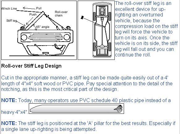
Roll-over stiff-legHere's a very cool idea borrowed from the professional recovery business:
Towing and Yanking vehicles for recovery.A common, quick and easy method of extracting a stuck vehicle is to connect another mobile vehicle to it and yank, pull, or tow it free. Because of the enormous forces generated in this type of operation, extreme care should be exercised. NEVER EVER use chain, wire rope, or a winch to yank another vehicle free. The shock loads developed can multiply the force applied many times, so that a stuck truck requiring a 10,000 lb steady pull to free, can cause a shock-load of 50 000 lbs if jerked or yanked suddenly. This is extremely dangerous to man and machine. As such, only properly designed, constructed, and rated recovery straps should ever be used for yanking vehicles free. DO NOT ever use tow ropes, tow straps, emergency tow ropes etc. These are designed only for easy flat road towing of a non-running vehicle (and are dubious for that, in my opinion) - not for the rigors of off-road extraction and recovery. |
|||||||||||||||||||||||||||||||||||||||||||||||||||||||||||||
 |
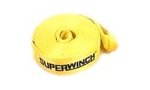
Off-road recovery straps. | ||||||||||||||||||||||||||||||||||||||||||||||||||||||||||||
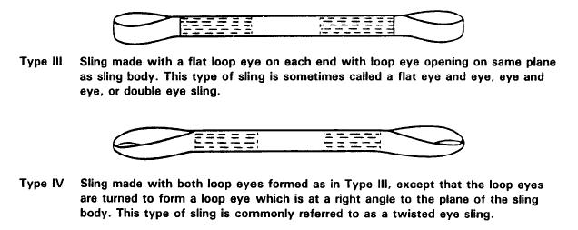 |
The proper recovery straps are designed to stretch when yanked, storing potential energy, which they then release as they "rebound" providing tremendous kinetic energy to free the stuck vehicle, in the safest manner possible. It is best and safest to use recovery straps that have no metal fittings, but rather just sewn loop ends (called eye and eye by industry). This diagram shows suitable types. | ||||||||||||||||||||||||||||||||||||||||||||||||||||||||||||
Make absolutely certain that the anchor points on the vehicles in question are capable of handling the loads imposed. Do not ever use recovery straps in combination with wire rope or chains or other devices. Do not join 2 recovery straps together by knotting them. |
|||||||||||||||||||||||||||||||||||||||||||||||||||||||||||||
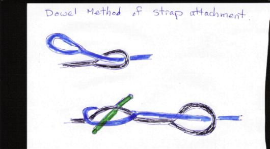 |
The proper method for joining two recovery straps together using a dowel. | ||||||||||||||||||||||||||||||||||||||||||||||||||||||||||||
Care and inspection:Care and inspection of nylon recovery straps is extremely important for safe operations, and almost EVERYONE neglects and abuses them (me included!). They should be stored free from water, dirt, and other chemicals. Before use they should be inspected carefully. Recovery straps are a specialized type of Synthetic Web Sling and as such, the following information, taken from the hoisting industry, regarding synthetic web slings, should be adhered to: The webbing from which the strap is constructed should have the following characteristics: 1. Sufficient certified tensile strength to meet the sling manufacturer's requirements Synthetic web slings may be coated with suitable material that will impart the following desirable characteristics: 1. Abrasion resistance Marking:Synthetic web slings shall be labeled (a sewn-on leather tag is recommended). The label shall state the following: 1. Manufacturer's name or trademark Design Factor.The design factor for synthetic web slings shall be a minimum of 5. High radiation or chemically active environments can destroy the strength of synthetic web slings. Sling materials can be susceptible to caustics and acids. Inspection:Synthetic web slings shall be removed from service if damage such as the following is visible: 1. Acid, phenolic, or caustic attack Operating Practices:The following operating practices are applicable to the use of synthetic web slings: 1. Slings having suitable characteristics for the type of load, hitch, and environment shall be selected. 6. Sharp corners in contact with the sling should be padded to minimize damage to the sling. Additional Reading:
Links:http://www.wreckmaster.com - Professional wreckers / recovery operator's school. Excellent tech info on site. http://www.gatorsupply.com - Good tech info from this professional Oilfield, Marine and Industrial Supplier http://www.hanford.gov - U.S. Department of Energy Hanford Site - excellent hoisting and rigging manual, document DOE-RL-92-36 http://publications.usace.army.mil/publications/eng-manuals/em1110-2-3200/entire.pdf - U.S. Army Engineering manual Engineering and Design - Wire Rope Selection Criteria For Gate-Operating Devices http://www.wireropenews.com/ - Industry wire rope news and sling technology http://www.liftlink.com/ - Liftlink.com http://www.recoverygear.com - Good recovery gear supplier http://www.rockstomper.com - Another favourite recovery gear supplier http://www.unirope.com/wireropes/wr_techinfo_main.shtml - Unirope professional industrial lifting supplier's Technical articles http://www.winchwarehouse.co.uk/default.htm - Winch Warehouse - U.K. recovery supplier. Related Abbreviations: AGMA--American Gear Manufacturers Association. AISC--American Institute of Steel Construction. AISE--Association of Iron and Steel Engineers. AISI--American Iron and Steel Institute. ANSI--American National Standards Institute. ASLE--American Society of Lubrication Engineers. ASM--American Society of Metals. ASME--American Society of Mechanical Engineers. ASNT--American Society for Nondestructive Testing. ASTM--American Society for Testing Materials. AWG--American Wire Gage. AWS--American Welding Society. DOE--U.S. Department of Energy. DOL--U.S. Department of Labor. DOT--U.S. Department of Transportation. HHRC--Hanford Hoisting and Rigging Committee. HMI--Hoist Manufacturers Institute. NDA--Nondestructive assessment. NDT--Nondestructive test. NEMA--National Electrical Manufacturers Association. NFPA--National Fire Protection Association. NLGI--National Lubricating Grease Institute. PCSA--Power Crane and Shovel Association. |
|||||||||||||||||||||||||||||||||||||||||||||||||||||||||||||
|
|||||||||||||||||||||||||||||||||||||||||||||||||||||||||||||

|