 |
Performance Off-Road Systems Hydo Steering By Bill "BillaVista" Ansell |
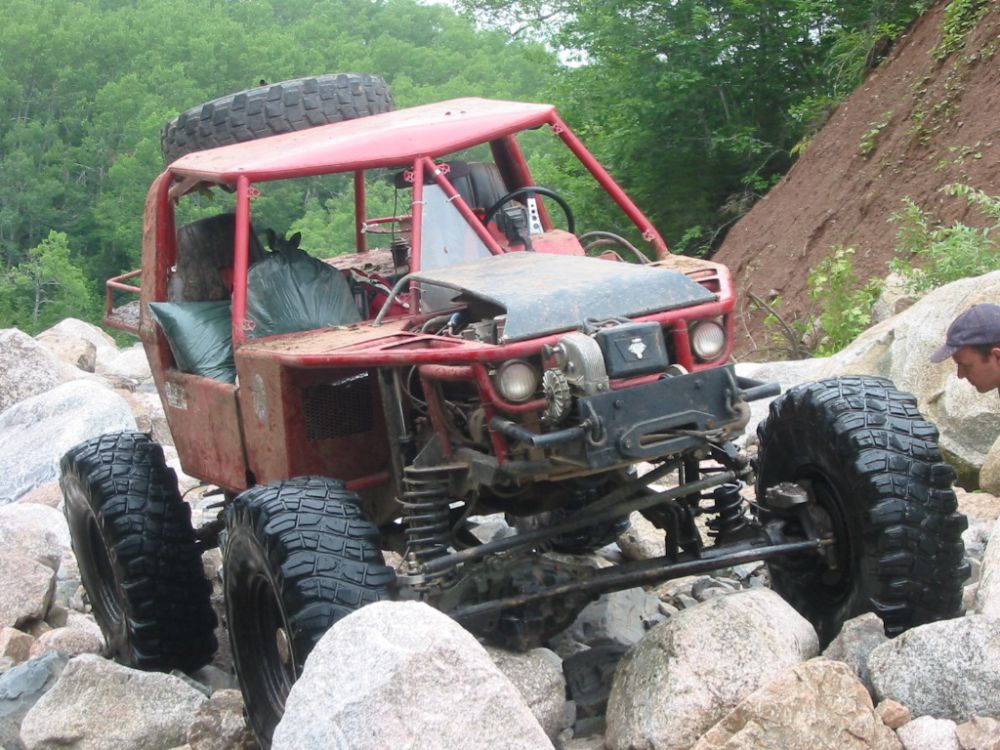
IntroductionOne of the most sought after modifications for the the hardcore off-roader, nothing says "I am serious about my vehicles off-road capability" like full hydraulic steering. Nothing screams "I will not compromise my rig's abilities" like a hydraulic steering unit and big ol' steering cylinder. When you see a rig with full hydraulic steering - it really says something about that rigs capabilities, and its owner/drivers mind-set. It's no secret that I have long lusted after hydro steering (full hydraulic steering) for my buggy, the Wolf. In case you haven't been following along... |
 |
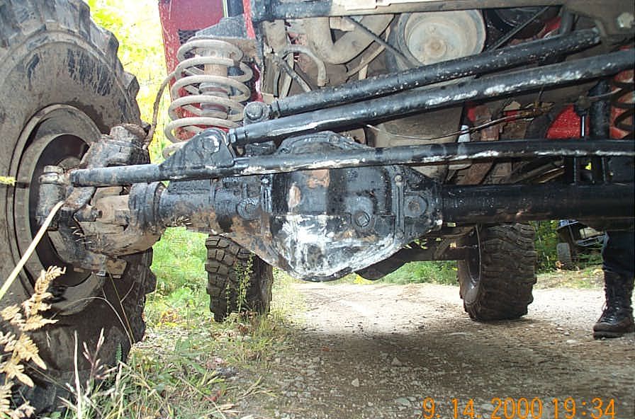 |
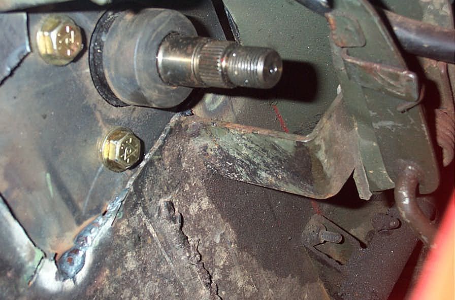
I was sick of this... | ||||||||||||||||||||||||||||||||||||||||||||||||||||||||||||||||||||||||||||||||||||||||||||||||||||||||||||||||||||||
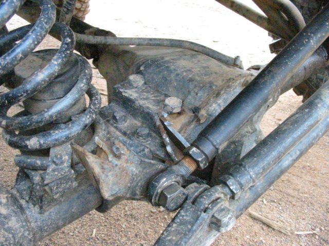 |
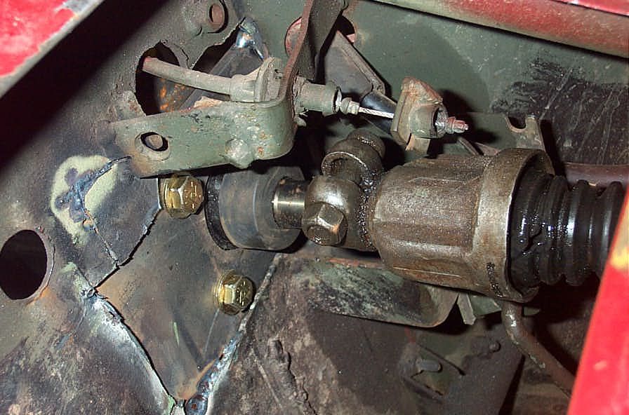
...and this... | ||||||||||||||||||||||||||||||||||||||||||||||||||||||||||||||||||||||||||||||||||||||||||||||||||||||||||||||||||||||
 |
...and this! | ||||||||||||||||||||||||||||||||||||||||||||||||||||||||||||||||||||||||||||||||||||||||||||||||||||||||||||||||||||||
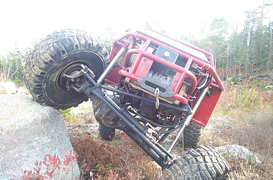
| Not to mention, with a spooled front differential (welded) and solid drive flanges in the hubs (in place of manual locking hubs) the Wolf was an Olympic workout to steer, especially when bound up in the rocks. The proverbial "final straw" was when poor old Scout II steering box finally puked it's guts, leaving me stranded, on the third (and best) day of our annual "rockathon" event, with no steering. My day was done, I was a spectator, amongst some of the best rock terrain we have. | |||||||||||||||||||||||||||||||||||||||||||||||||||||||||||||||||||||||||||||||||||||||||||||||||||||||||||||||||||||||
 |
"Hey...what's that peeing out from the sector shaft area...?" | ||||||||||||||||||||||||||||||||||||||||||||||||||||||||||||||||||||||||||||||||||||||||||||||||||||||||||||||||||||||
 |
"Oh good...I get to park while everyone else gets it awwwn in Rock City!" | ||||||||||||||||||||||||||||||||||||||||||||||||||||||||||||||||||||||||||||||||||||||||||||||||||||||||||||||||||||||
BOY was I ticked off. And so began some loooong nights of research, which I attacked in my customary style. Eventually, my search led me to Sean Stapely of Performance Offroad Systems. He is a small one-man operation that specializes in Hydraulic steering components and systems. He came highly recommended by quite a long list of folks I highly respect, including "Diamond" Dan Dibble and Frankie "Finland" Fountain. So I decided to give him a call and see what he had to say, and to offer. Read along to see what I got, what I dod right, what I did wrong, what I learned, and what I thought. Be warned, this is not a simple or cheap upgrade or modification. It can be complex, and very costly - especially if you have additional system complexities such as hydroboost brakes or 4-wheel steering requirements. However, done right, it can and will reward you with steering like no other you have EVER experienced. And I do mean EVER. Not just in a 4x4 or Rock Buggy, I mean EVER. Read on and I shall explain... The Parts |
|||||||||||||||||||||||||||||||||||||||||||||||||||||||||||||||||||||||||||||||||||||||||||||||||||||||||||||||||||||||
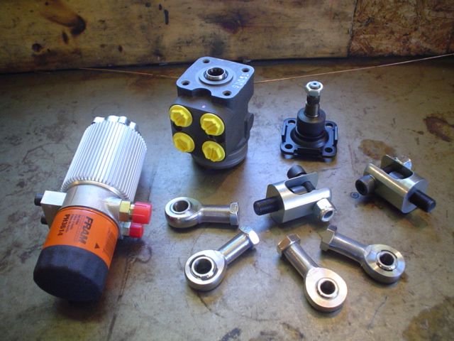 |
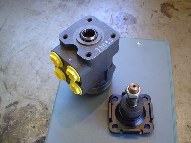
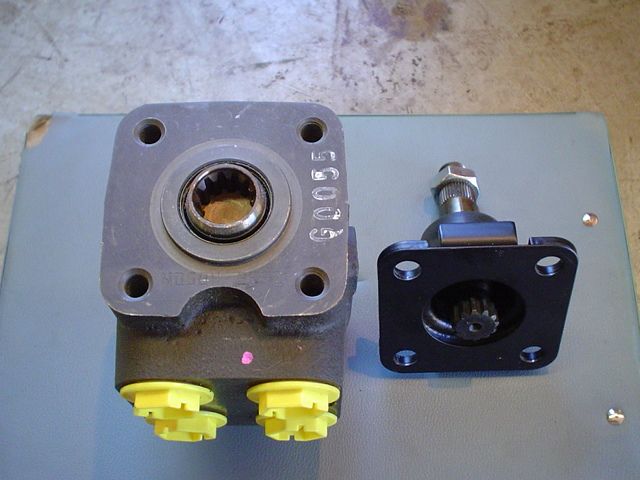
The system I ordered from Performance Off-Road Systems included a Danfoss Steering Unit, Custom Steering shaft, Integrated fluid Cooler/Filter/Reservoir (CFR), Custom Balanced (double-ended) cylinder with mounting clamps, Double-shear Clevis ends for the cylinder and 4 QA1 Endura series spherical rod ends (Heim joints) - 2 - 3/4"x5/8" and 2 - 3/4" x 3/4" . If you are unfamiliar with any of these terms or components, I highly recommend you first read Hydraulic Steering Systems. | ||||||||||||||||||||||||||||||||||||||||||||||||||||||||||||||||||||||||||||||||||||||||||||||||||||||||||||||||||||||
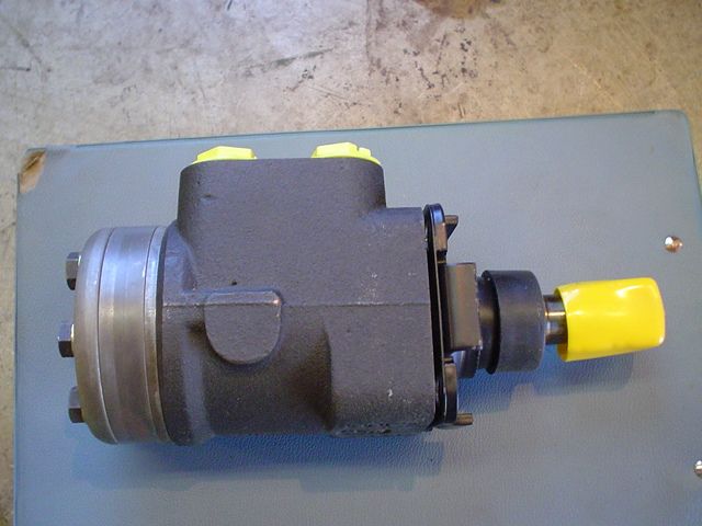 |
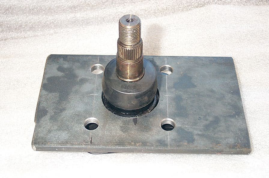
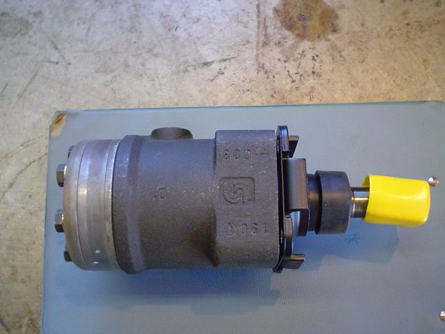
The heart of the system is the Danfoss Steering Unit, seen here with the steering shaft attached. | ||||||||||||||||||||||||||||||||||||||||||||||||||||||||||||||||||||||||||||||||||||||||||||||||||||||||||||||||||||||
 |
The steering unit is an open-center, load-reactive unit. It weighs 12 lbs, displaces approximately 7 cu. in. / rev. and requires a pump capable of producing flow rates of 3.4-13.2 gpm. It has a built-in manual check-valve that allows manual steering (pump inoperative). | ||||||||||||||||||||||||||||||||||||||||||||||||||||||||||||||||||||||||||||||||||||||||||||||||||||||||||||||||||||||
 |
The ports are all 3/4-16 UNF O-ring boss. | ||||||||||||||||||||||||||||||||||||||||||||||||||||||||||||||||||||||||||||||||||||||||||||||||||||||||||||||||||||||
 |
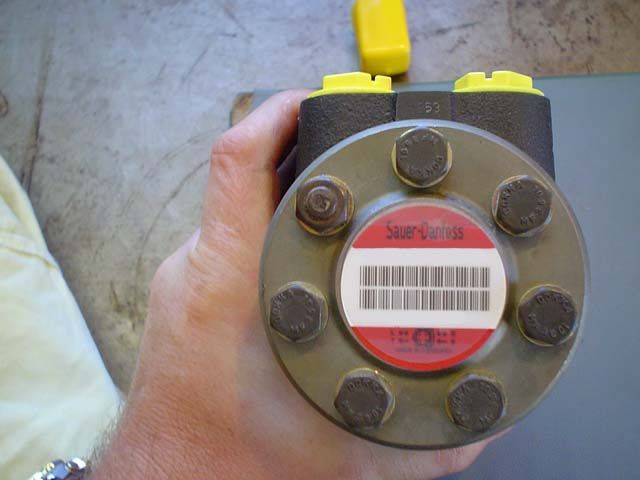
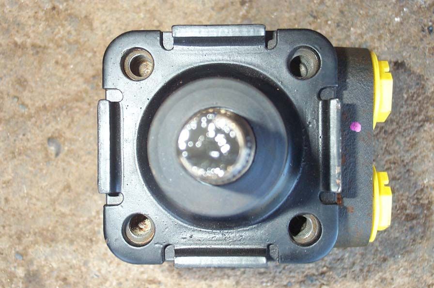
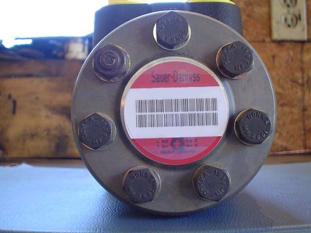
Shows the input end of the steering unit, as well as the 4 threaded holes to which a) the steering input shaft bolts; and b) the steering unit is mounted to the vehicle. | ||||||||||||||||||||||||||||||||||||||||||||||||||||||||||||||||||||||||||||||||||||||||||||||||||||||||||||||||||||||
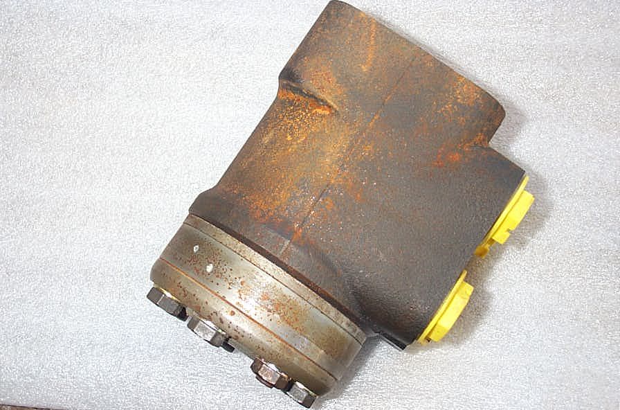 |
The steering unit does need to be coated or painted before being exposed to the elements at all. I left it in the garage for a week and surface rust began, so a quick coat of paint would be a good idea. DO NOT get any paint anywhere near any of the hydraulic ports or seals! | ||||||||||||||||||||||||||||||||||||||||||||||||||||||||||||||||||||||||||||||||||||||||||||||||||||||||||||||||||||||
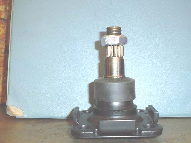 |
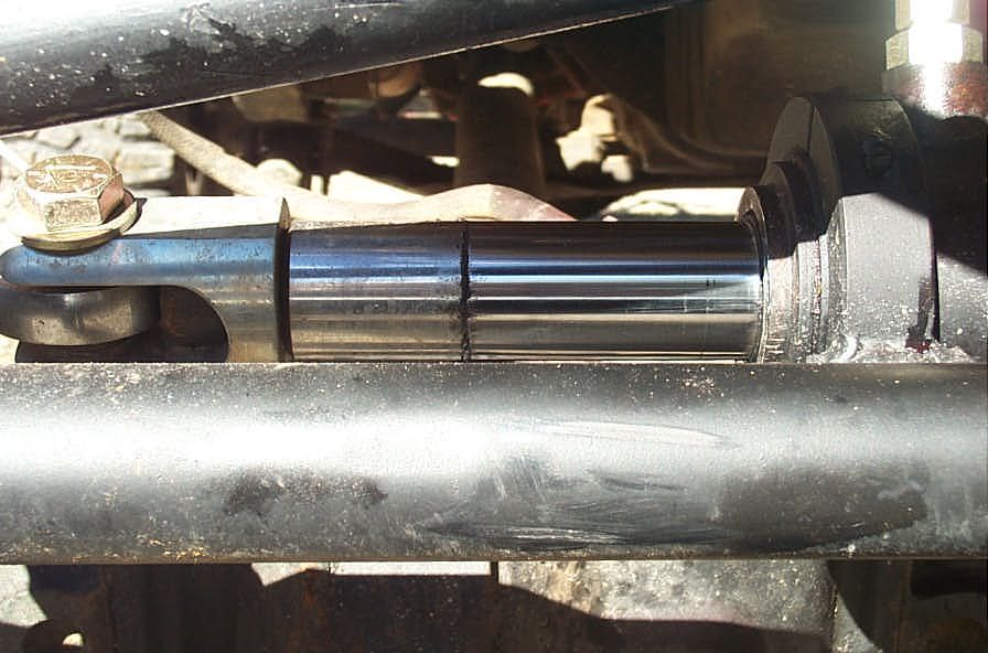
This is the Performance Off-Road Systems custom steering shaft. The splined section is specifically manufactured in 36 spline .750" ,which is the common automotive steering shaft spline size, to fit standard automotive parts, as opposed to most other shafts are a common agriculture size that sends you searching for agricultural parts to match. | ||||||||||||||||||||||||||||||||||||||||||||||||||||||||||||||||||||||||||||||||||||||||||||||||||||||||||||||||||||||
 |
For some odd reason the holes on my steering shaft did not line up exactly with the tapped holes in the steering unit. I tried in in every possible orientation - but still things would not line up exactly. It wasn't a huge deal, as the holes in the steering shaft base plate were sufficiently large to allow all the bolts to go in. However, it did make things fiddley as heck trying to get the bolts all in place when trying to mount the steering unit to the firewall, as the bolts have to go through the firewall mounting plate, then steering shaft base plate, then into the steering unit. To get this all lined up the holes on the firewall mounting plate had to be drilled oversize by quite a bit (29/64" for 3/8" bolts). | ||||||||||||||||||||||||||||||||||||||||||||||||||||||||||||||||||||||||||||||||||||||||||||||||||||||||||||||||||||||
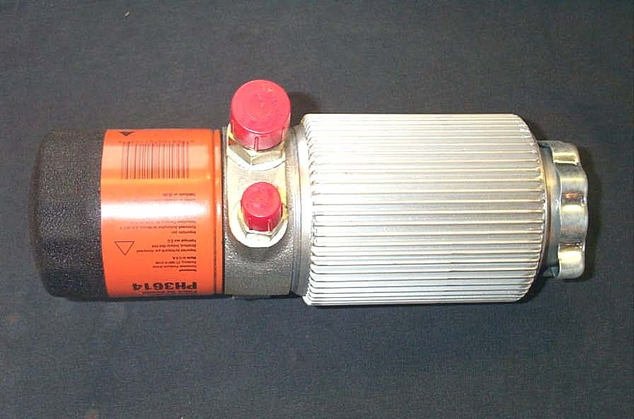 |
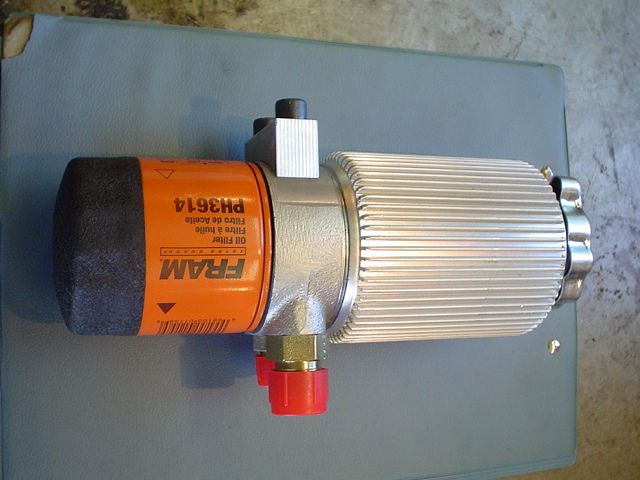
The Cooler/Filter/Reservoir combo is from Appleton. It's aluminum and features integrated fins for cooling, a standard automotive engine oil spin-on filter ( ) , and a reservoir capacity of approximately 1.5 litres. It has a -10 JIC (AN) outlet fitting and a -6 JIC (AN) inlet fitting. | ||||||||||||||||||||||||||||||||||||||||||||||||||||||||||||||||||||||||||||||||||||||||||||||||||||||||||||||||||||||
 |
It also has an integrated mounting block, shown at the top of this pic. | ||||||||||||||||||||||||||||||||||||||||||||||||||||||||||||||||||||||||||||||||||||||||||||||||||||||||||||||||||||||
 |
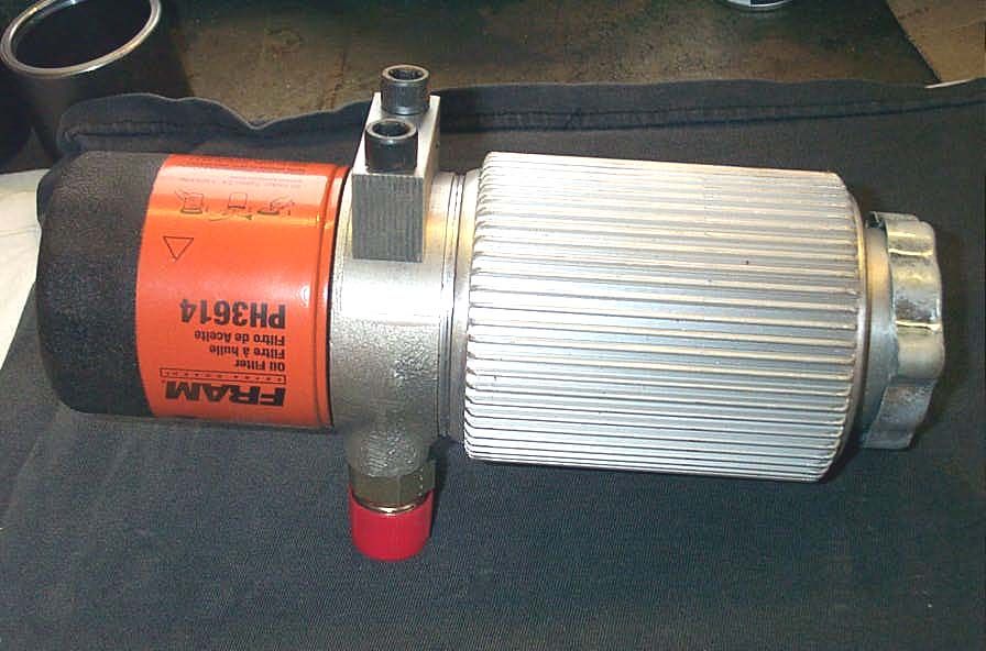
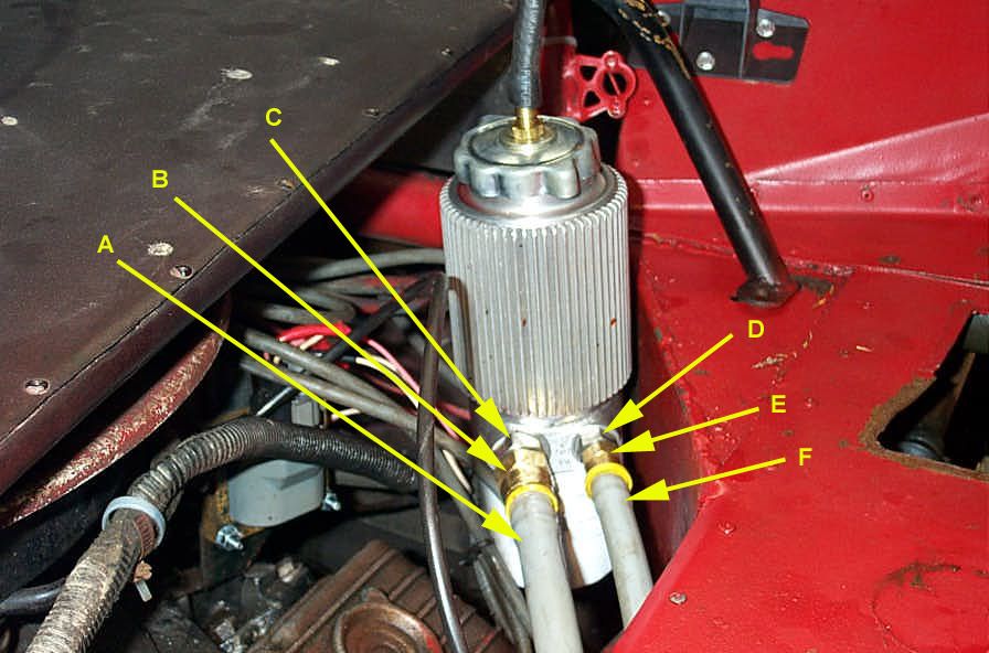
The fluid path through the unit is as follows. Fluid enters through the "return" port (bottom right in this pic). It flows through the small orifice shown, and then enters the filter through the multiple smaller circular holes around the filter. It passes through the filter media and exits the filter through the central hole. From there it enters the reservoir again through the large central port (the one onto which the filter screws) shown in the center in the pic at left. | ||||||||||||||||||||||||||||||||||||||||||||||||||||||||||||||||||||||||||||||||||||||||||||||||||||||||||||||||||||||
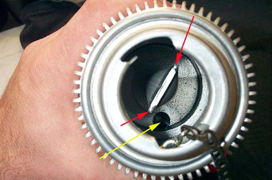 |
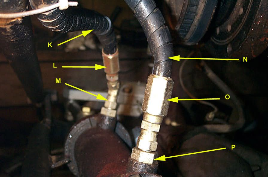
From the center hole of the filter it flows up through this column that is in the middle of the reservoir, and exits through 2 small ports in the column (red arrows indicate location), that are about 1/2-1" below the top of the column. This arrangement is designed to reduce aeration of the fluid as it returns to the reservoir. It is a form of baffling. Finally, the fluid exits through the large circular port in the bottom of the reservoir (yellow arrow)... |
||||||||||||||||||||||||||||||||||||||||||||||||||||||||||||||||||||||||||||||||||||||||||||||||||||||||||||||||||||||
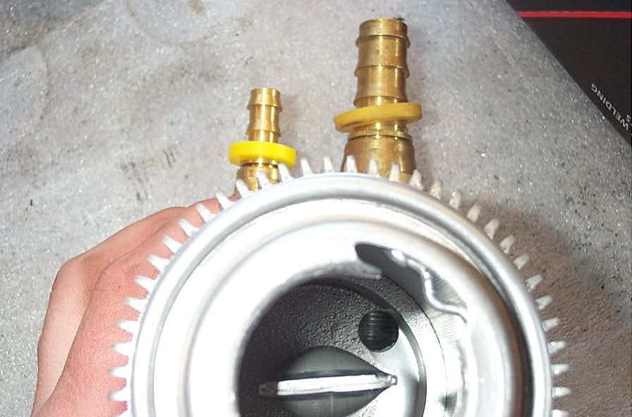 |
... and out the -10 fitting to the pump (fitting on right in pic at left) | ||||||||||||||||||||||||||||||||||||||||||||||||||||||||||||||||||||||||||||||||||||||||||||||||||||||||||||||||||||||
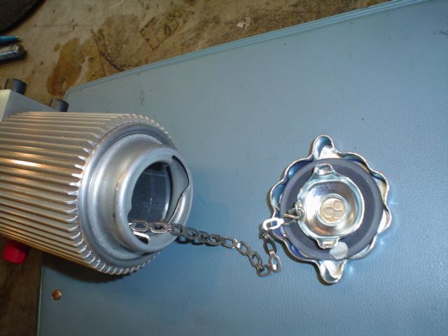 |
The CFR has a steel 1/4 turn cap attached by a small chain. This leads me to my first, hopefully constructive, criticism. The cap supplied with the CFR is a fully sealing kind. As discussed in Part 2, and indeed as Sean himself recommends, the system should be run vented. However, a vented cap is not supplied, nor available, from Performance Off-Road Systems or from any other source that I could find (and I tried all kinds of gas, oil, and radiator caps - buying several to try).This leaves you with only 3 choices:
|
||||||||||||||||||||||||||||||||||||||||||||||||||||||||||||||||||||||||||||||||||||||||||||||||||||||||||||||||||||||
 |
To start with, the only place you can vent the cap is in the center, but as you can see from the pic, the whole cap is held together by spot welds - so when you drill your vent hole, it all falls apart. | ||||||||||||||||||||||||||||||||||||||||||||||||||||||||||||||||||||||||||||||||||||||||||||||||||||||||||||||||||||||
 |
I solved this problem by drilling a large hole, and fitting a pipe-thread hose barb... | ||||||||||||||||||||||||||||||||||||||||||||||||||||||||||||||||||||||||||||||||||||||||||||||||||||||||||||||||||||||
 |
...held on the backside with a pipe coupling I cut in half to produce a sort of NPT "nut" to hold all the little bits back together with the nipple fitting. This led to another little SNAFU. As you can imagine, through this process, the exact orientation of the little locking tabs of the cap changed somewhat. While getting them re-aligned so the cap would go on and off easily enough but still stay tight the steel galled the aluminum of the lip of the tank and left me with a small pile of aluminum shavings in the bottom of the tank - as you can imagine - not the best of things for a hydraulic reservoir! All in all - nothing major, possibly caused by my own ineptitude, but like I said, a royal pain that could easily be avoided with a proper vented cap offering. |
||||||||||||||||||||||||||||||||||||||||||||||||||||||||||||||||||||||||||||||||||||||||||||||||||||||||||||||||||||||
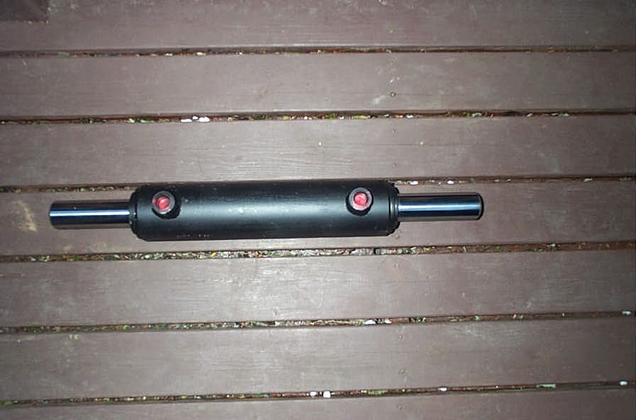 |
Moving on...the "other" heart of the system, my personal favourite component, and the part that makes the Performance Off-Road Systems system the best available on the market is the balanced , double-acting steering cylinder. | ||||||||||||||||||||||||||||||||||||||||||||||||||||||||||||||||||||||||||||||||||||||||||||||||||||||||||||||||||||||
 |
This beast is custom designed and built to spec specifically for off-road hydro steering systems on hardcore rock smacking machines. You won't find any other available quite like it, and it is FAR superior to any other offered. It has a 2.5" bore , 8" stroke , 1.5" diameter IHCP( Induction hardened, Chrome plated) shaft and .25" wall thickness on the body of the cylinder. The length is 21.5" + the length of the clevice ends. Built to take a serious beating, able to handle the unique stresses of rock crawling, and easily able to handle the pressure of the most hi-po pumps and generate tremendous amounts of steering power...this beauty may not be shiny but it definitely gets the job done! |
||||||||||||||||||||||||||||||||||||||||||||||||||||||||||||||||||||||||||||||||||||||||||||||||||||||||||||||||||||||
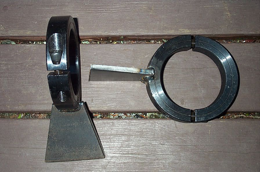 |
In the same vein, the supplied mounting brackets are simple, no nonsense pieces that are easy to mount and provide great ease and flexibility in mounting the cylinder... | ||||||||||||||||||||||||||||||||||||||||||||||||||||||||||||||||||||||||||||||||||||||||||||||||||||||||||||||||||||||
 |
...and that's a very good thing because the big, beefy cylinder is 3" OD alone, and 4.5" OD with the brackets around it - so it takes up quite a bit of real estate and therefore mounting can be challenging. | ||||||||||||||||||||||||||||||||||||||||||||||||||||||||||||||||||||||||||||||||||||||||||||||||||||||||||||||||||||||
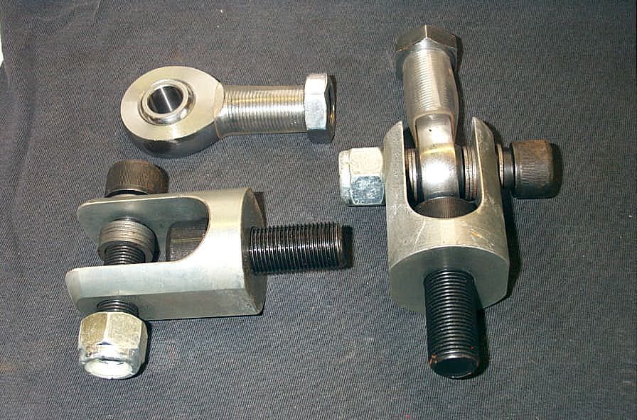 |
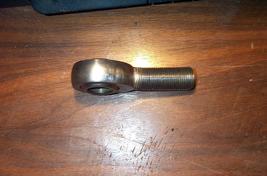
The system is rounded out nicely with this very nice linkage hardware. There are 2 double shear style clevis ends that thread into the ends of the cylinder, socket head cap screws with nylock nuts to attach the rod ends to the clevis ends, and a total of 4 QA1 Endura series rod ends. | ||||||||||||||||||||||||||||||||||||||||||||||||||||||||||||||||||||||||||||||||||||||||||||||||||||||||||||||||||||||
 |
This gives you a basic idea of the arrangement, with the cylinder on the left of the pic and the knuckles steering arm on the right. Note, the mini tie rod shown is not included. | ||||||||||||||||||||||||||||||||||||||||||||||||||||||||||||||||||||||||||||||||||||||||||||||||||||||||||||||||||||||
 |
Two of the rod ends are 3/4" shank and 5/8" ball bore and are used to connect the rod end of your mini tie rods to the clevis end of the cylinder (pic at left). the other 2 rod ends are 3/4" shank and 3/4" bore for attaching the other end of your mini tie-rod to the knuckles steering arm. As can be seen at left, 6 small machine washers are included for use with each clevis, to center the rod end between the jaws of the clevis. I found, however, that the supplied socket head cap screws left the threads between the jaws of the clevis, so the washers and rod end would be bearing against the threads instead of the full 3/4" shank diameter. |
||||||||||||||||||||||||||||||||||||||||||||||||||||||||||||||||||||||||||||||||||||||||||||||||||||||||||||||||||||||
 |
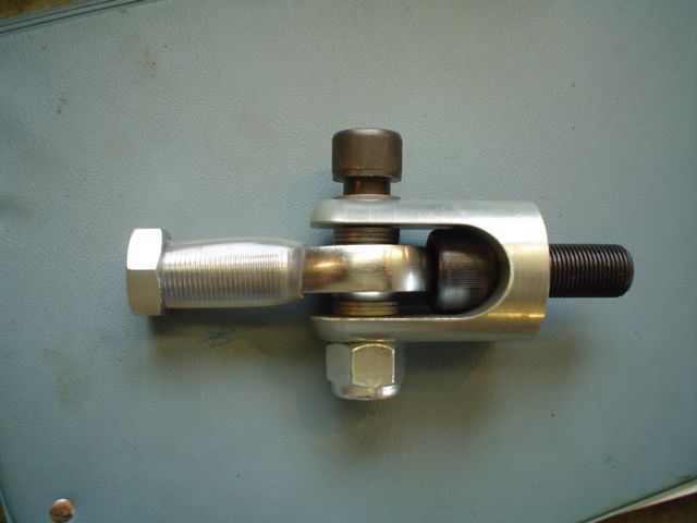
I wasn't happy with this arrangement so replaced the supplied socket head cap screws with some Bowman Grade 8 hex head cap screws (bolts) that left a full shank diameter between the jaws. | ||||||||||||||||||||||||||||||||||||||||||||||||||||||||||||||||||||||||||||||||||||||||||||||||||||||||||||||||||||||
InstallationSteering UnitOne of the great benefits to hydro steering is the enormous flexibility one has in mounting the steering unit, which then only connects to the steering cylinder (mounted to the axle) via flexible hydraulic lines. This opposed to conventional power steering where the steering gearbox must fit in a very specific location such that it can be joined via mechanical linkage to both the steering wheel and the steering knuckles (via the pitman arm and drag link / tie rod). The steering unit can be mounted virtually anywhere, within reason. However, there is a very important safety consideration to take into account. I have seen many hydro steering systems setup with the steering unit mounted inside the cockpit, connected to the steering wheel by only a very short steering column. While this may make for a convenient and "clean" install it is, in my opinion, EXTREMELY DANGEROUS and therefore very very ill advised. This is because of a concept known as fluid injection. A fluid injections is a fine stream of escaping pressurized fluid that can penetrate skin and enter a human body. These fluid injections may cause severe tissue damage and loss of limb. Not only will a fine stream of hydraulic fluid at 1500 psi slice through body tissue like a hot knife, the resulting injection of pressurized toxic fluid deep into the body can cause all manner of very serious medical complications. From SAE j1273 "RECOMMENDED PRACTICES FOR HYDRAULIC HOSE ASSEMBLIES": "Consider various means to reduce the risk of fluid injections, particularly in areas normally occupied by operators. Consider careful routing, adjacent components, warnings, guards, shields, and training programs. Relieve pressure before disconnecting hydraulic or other lines. Tighten all connections before applying pressure. Avoid contact with escaping fluids. Treat all leaks as though pressurized and hot enough to burn skin. Never use any part of your body to check a hose for leaks. If a fluid-injection accident occurs, see a doctor immediately. DO NOT DELAY OR TREAT AS A SIMPLE CUT! Any fluid injected into the skin must be surgically removed within a few hours or gangrene may result. Doctors unfamiliar with this type of injury should consult a knowledgeable medical source. Whipping Hose—If a pressurized hose assembly blows apart, the fittings can be thrown off at high speed, and the loose hose can flail or whip with great force. This is particularly true in compressible-fluid systems. When this risk exists, consider guards and restraints to protect against injury." Pretty scary stuff - so the steering unit should definitely be mounted outside the cockpit / driver compartment. |
|||||||||||||||||||||||||||||||||||||||||||||||||||||||||||||||||||||||||||||||||||||||||||||||||||||||||||||||||||||||
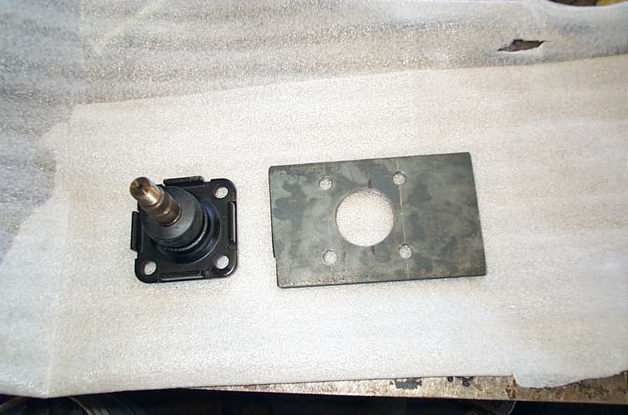 |
I made a small 1/4" mounting plate... | ||||||||||||||||||||||||||||||||||||||||||||||||||||||||||||||||||||||||||||||||||||||||||||||||||||||||||||||||||||||
 |
...that fit over the steering column... | ||||||||||||||||||||||||||||||||||||||||||||||||||||||||||||||||||||||||||||||||||||||||||||||||||||||||||||||||||||||
 |
...and welded it to the firewall... | ||||||||||||||||||||||||||||||||||||||||||||||||||||||||||||||||||||||||||||||||||||||||||||||||||||||||||||||||||||||
 |
...so that the steering unit was up high out of harms way, close enough to the driver to allow for a simple, short steering column, but still safely on the other side of the firewall. | ||||||||||||||||||||||||||||||||||||||||||||||||||||||||||||||||||||||||||||||||||||||||||||||||||||||||||||||||||||||
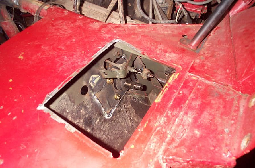 |
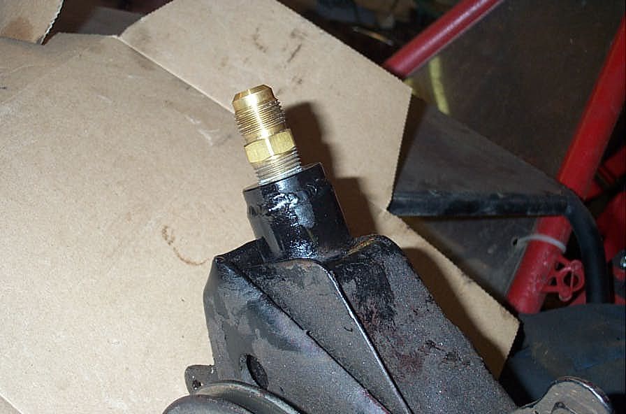
The stub steering shaft is all that pokes through the firewall... | ||||||||||||||||||||||||||||||||||||||||||||||||||||||||||||||||||||||||||||||||||||||||||||||||||||||||||||||||||||||
 |
...leaving the 36 spline shaft for you to connect your steering column/shaft too. | ||||||||||||||||||||||||||||||||||||||||||||||||||||||||||||||||||||||||||||||||||||||||||||||||||||||||||||||||||||||
 |
I used an old shaft from an F250 that had this neat flexible coupling that, of course, fit perfectly onto the steering shaft from Performance Off-Road Systems. The other end of the column (really just a solid 3/4" steel shaft) runs through a bearing for support under the "dash" and then has the quick-disconnect coupling for my steering wheel welded to it. |
||||||||||||||||||||||||||||||||||||||||||||||||||||||||||||||||||||||||||||||||||||||||||||||||||||||||||||||||||||||
CylinderOne of the most tricky parts of the installation is mounting the steering cylinder and getting the geometry right. of course, every installation will be custom and so no set of instructions can completely describe the process for everyone, but some general guidelines may help: |
|||||||||||||||||||||||||||||||||||||||||||||||||||||||||||||||||||||||||||||||||||||||||||||||||||||||||||||||||||||||
 |
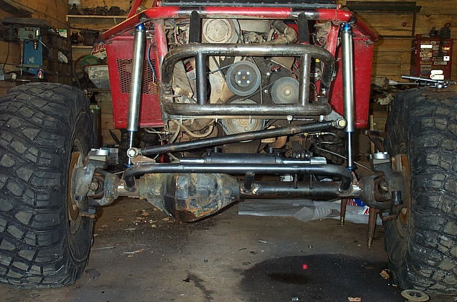
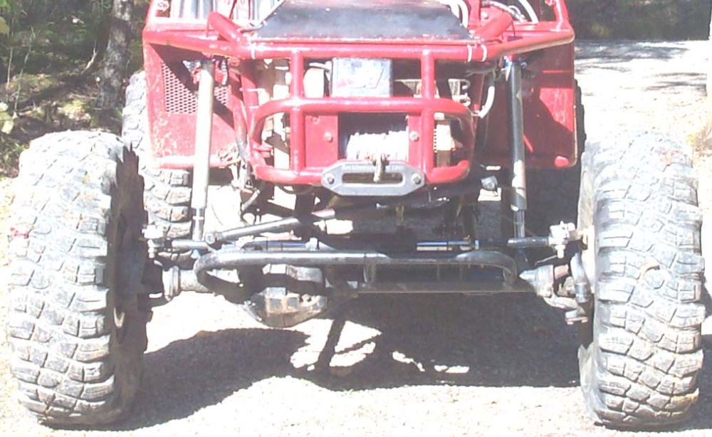
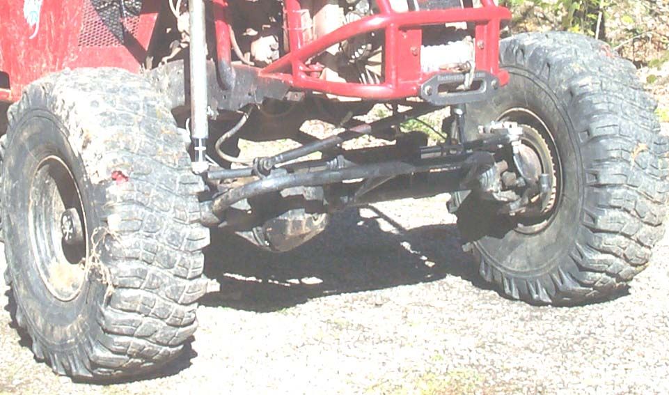
No matter how robust the cylinder, you don't want it left vulnerable, hanging out front to get damaged. I built a large truss from 1.75" tubing angled forward and up in front of the axle to serve as both a skid plate / guard for the cylinder as well as a place to mount the cylinder. You can see from this pic that the cylinder is extremely well protected. |
||||||||||||||||||||||||||||||||||||||||||||||||||||||||||||||||||||||||||||||||||||||||||||||||||||||||||||||||||||||
 |
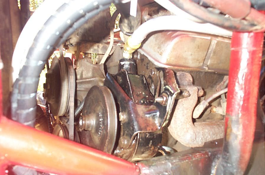
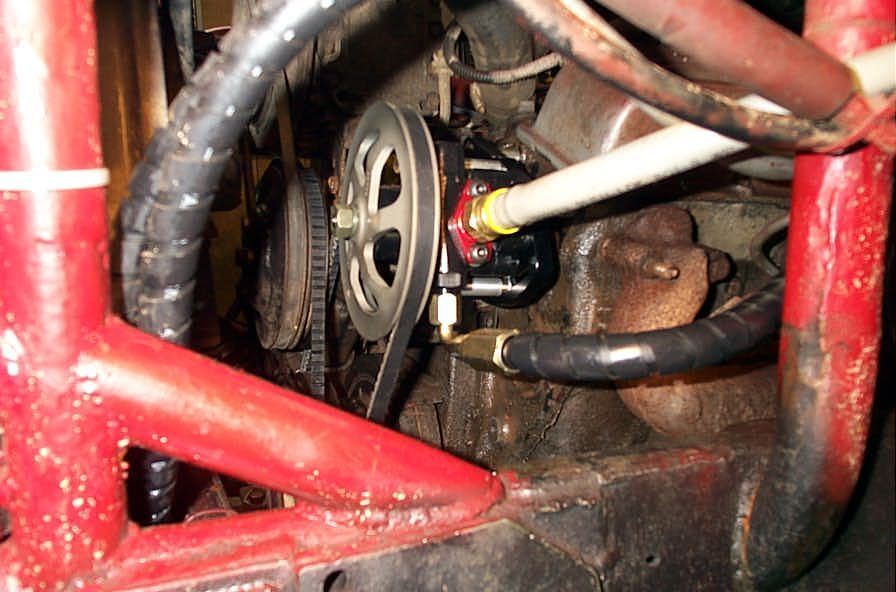
I tried various positions, eventually settling on as high and far back as possible without interfering with the crank pulley on full suspension compression. | ||||||||||||||||||||||||||||||||||||||||||||||||||||||||||||||||||||||||||||||||||||||||||||||||||||||||||||||||||||||
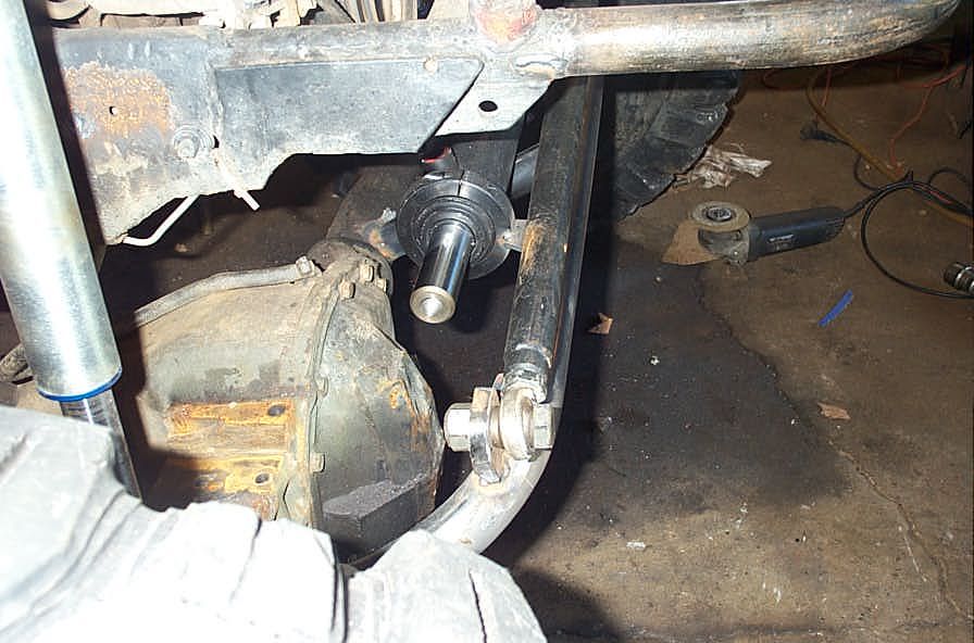 |
Clearance from the diff cover is an issue. Not only must the cylinder shaft obviously not hit the cover, but it would also be a large PITA to have to remove the cylinder every time you wanted to remove the cover. We managed to get my cylinder positioned so that it clears the cover, the cover can come off without moving the cylinder, and yet the cylinder is not too far offset to one side of the axle. |
||||||||||||||||||||||||||||||||||||||||||||||||||||||||||||||||||||||||||||||||||||||||||||||||||||||||||||||||||||||
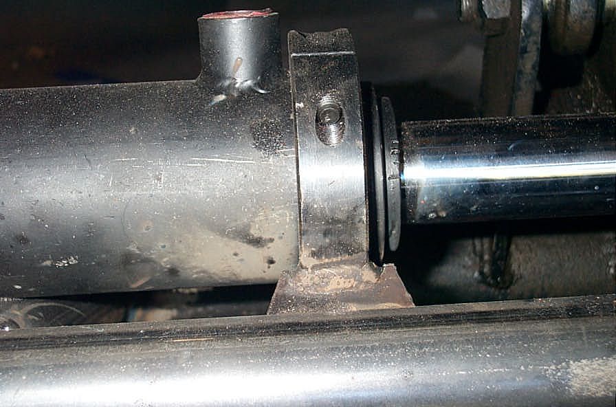 |
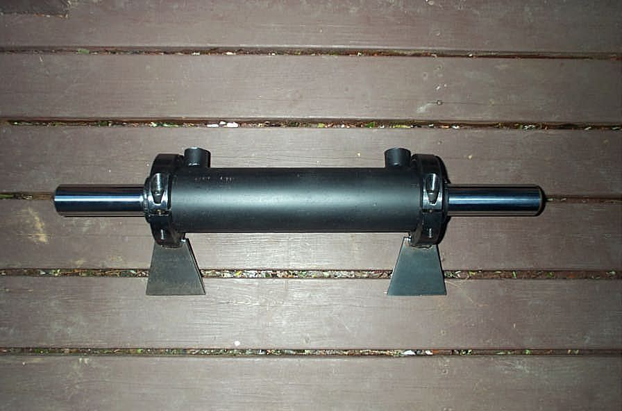
Here are the clamps in place around the cylinder and welded to the truss. | ||||||||||||||||||||||||||||||||||||||||||||||||||||||||||||||||||||||||||||||||||||||||||||||||||||||||||||||||||||||
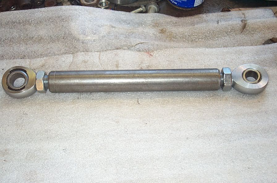 |
Mini tie rods have to be constructed to connect the ends of the cylinders shafts to the steering arms on the knuckles. | ||||||||||||||||||||||||||||||||||||||||||||||||||||||||||||||||||||||||||||||||||||||||||||||||||||||||||||||||||||||
|
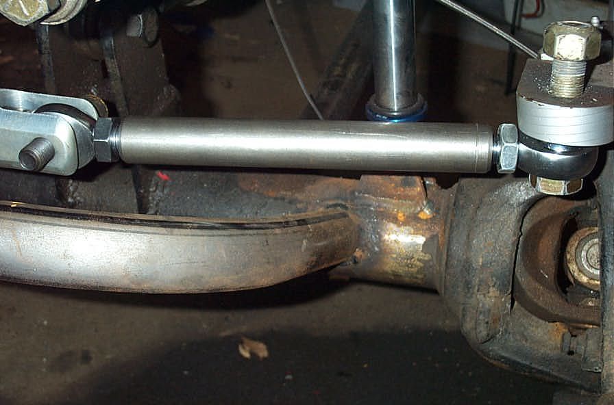
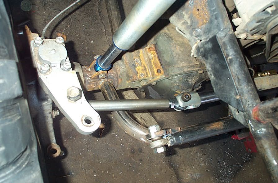
This is an early mock-up showing how the tie rods are positioned. There is one each side. | ||||||||||||||||||||||||||||||||||||||||||||||||||||||||||||||||||||||||||||||||||||||||||||||||||||||||||||||||||||||
 |
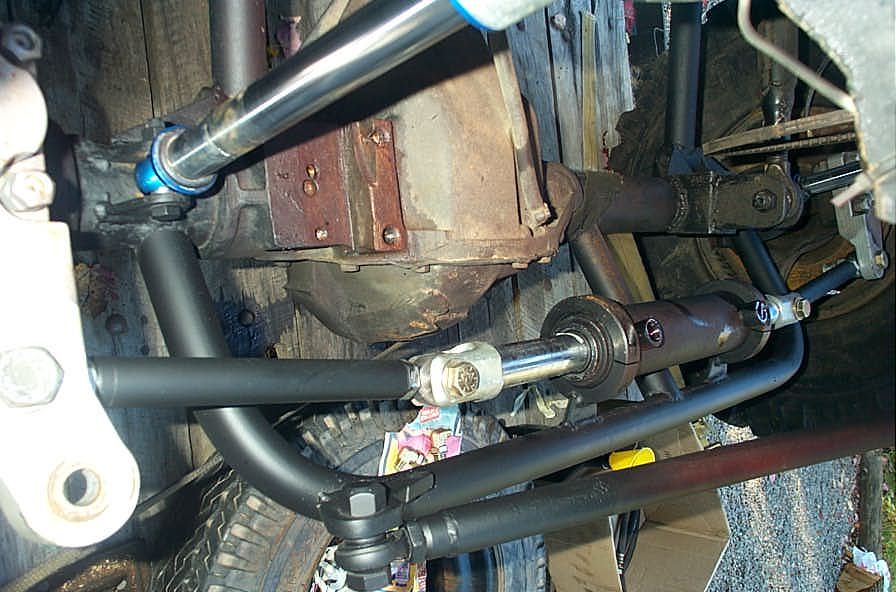
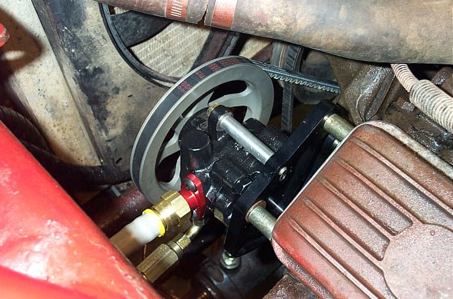
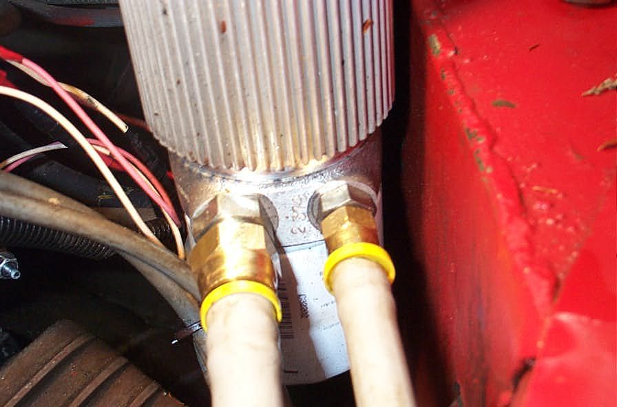
Cylinder clamped in place with ports facing up. The port on the left side of the cylinder (as viewed from the drivers seat) is the one to which you direct fluid to extend the shaft to the right, thereby steering the vehicle right. In other words, the left-end port is Right, and the right-end port is Left. | ||||||||||||||||||||||||||||||||||||||||||||||||||||||||||||||||||||||||||||||||||||||||||||||||||||||||||||||||||||||
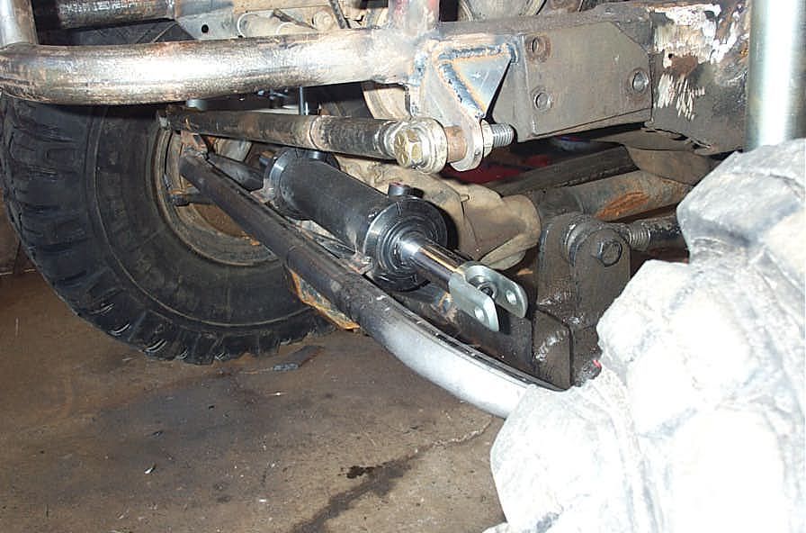 |
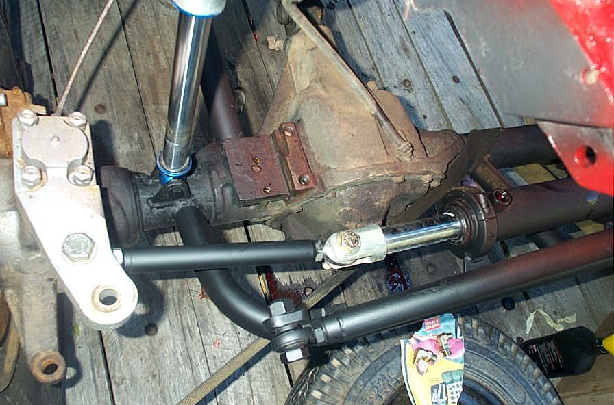
A side shot showing the positioning. The cylinder does not have to be mounted dead center in the middle of the axle (which is a good thing, because if it did, either the diff would be in the way, or you would have to have it stuck way too far out in front). However, you should not mount it such that it is more than 30% off center. this is because, the more off center it is, the greater the difference in length between the 2 mini tie rods. If the shorter of the tie rods gets too short, it will have to move in too much of an arc as it's knuckle steers from full left to full right. As it moves through this arc, if there is too much of an angle created between the knuckle and the cylinder shaft, undesirable side loads can be imposed on the cylinder shaft that can wear or damage seals or the shaft itself. having said that, the Performance Off-Road Systems cylinder is the biggest and strongest available, specifically designed to be able to handle some degree of side-loading. |
||||||||||||||||||||||||||||||||||||||||||||||||||||||||||||||||||||||||||||||||||||||||||||||||||||||||||||||||||||||
 |
Here you can see what I mean about the angle of the tie rod. In these initial installation pics, you will notice that I am using my OTT steering arms. However, a problem readily became apparent with the use of these arms with my new setup / geometry. |
||||||||||||||||||||||||||||||||||||||||||||||||||||||||||||||||||||||||||||||||||||||||||||||||||||||||||||||||||||||
|
Because the OTT arms are designed to be able to accommodate virtually all combinations of rims and backspacing, the distance from the center of the kingpin to the tie rod holes is quite short, in the order of 4.5" I believe. This means that, in order for the cylinder and tie rods to all lie in a nice straight line, the cylinder itself would have to be mounted virtually directly on top of the axle tube. And the problem with that approach is that you would need a lot of "lift" in order to create the space necessary and not have the cylinder smacking the crank snout or radiator or chasis. |
||||||||||||||||||||||||||||||||||||||||||||||||||||||||||||||||||||||||||||||||||||||||||||||||||||||||||||||||||||||
 |
I was unwilling to add any chasis height for this purpose, so I mounted the cylinder where I wanted it and made do with the mini tie rods angling back to the short steering arms. | ||||||||||||||||||||||||||||||||||||||||||||||||||||||||||||||||||||||||||||||||||||||||||||||||||||||||||||||||||||||
 |
However, this created tie rod angles I am not happy with and also resulted in me being unable to use the cylinders full 8" stroke. As I write this I am currently working on a new steering arm setup that will have the kingpin-to-tie-rod-hole distance closer to 6.5 or 7". This will allow full use of the entire cylinder stroke and allow me to keep the mini tie rod in a straight line with the cylinder shaft when the shaft is fully extended and at it's most vulnerable. Stay tuned for an update later on.... |
||||||||||||||||||||||||||||||||||||||||||||||||||||||||||||||||||||||||||||||||||||||||||||||||||||||||||||||||||||||
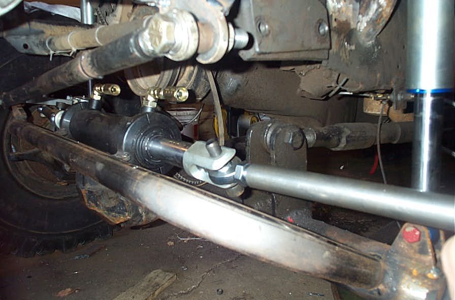 |
Pic showing tight spacing between panhard bar in front and crank pulley behind the cylinder. | ||||||||||||||||||||||||||||||||||||||||||||||||||||||||||||||||||||||||||||||||||||||||||||||||||||||||||||||||||||||
 |
When setting up the cylinder, you also need to account for any cylinder stroke not used because of your geometry. In other words, you MUST have the cylinder run out of stroke before, or right as, the steering stops are reached. This is because of the enormous force possible from the system. If the steering stops hit before the cylinder is out of stroke, and the pump is producing healthy flow and pressure, it is quite conceivable that continuing to turn the steering wheel after the knuckles reach their stops would simply shear the knuckles right off the housing. |
||||||||||||||||||||||||||||||||||||||||||||||||||||||||||||||||||||||||||||||||||||||||||||||||||||||||||||||||||||||
 |
Even though my initial geometry was not great, and the angled tie rods and short steering arms meant the cylinder had an inch of stroke left after the steering stops hit, I was unable to test the knuckle shearing theory (though I did try) as my pump at the time was anaemic and weak. | ||||||||||||||||||||||||||||||||||||||||||||||||||||||||||||||||||||||||||||||||||||||||||||||||||||||||||||||||||||||
 |
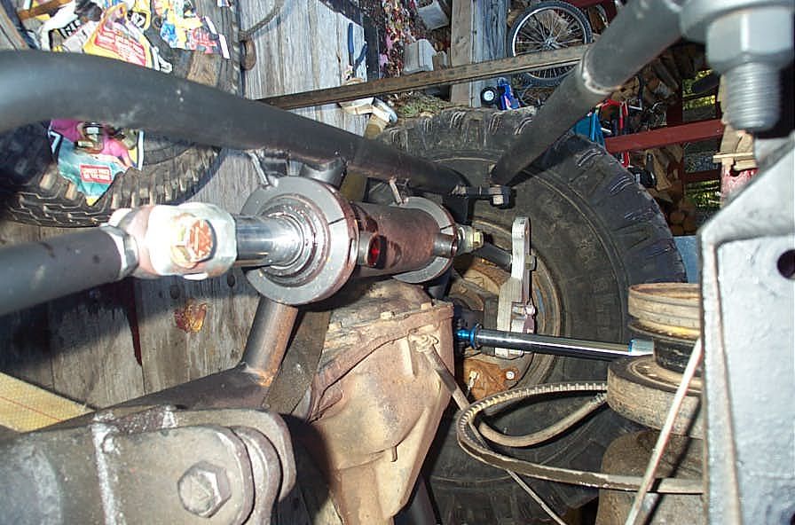
Shot showing knuckle to knuckle geometry of original design. | ||||||||||||||||||||||||||||||||||||||||||||||||||||||||||||||||||||||||||||||||||||||||||||||||||||||||||||||||||||||
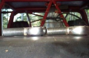 |
Even though my initial testing was done with a weak pump, and didn't include any real hardcore wheeling, somehow I managed to bend one of the outer-most rod ends. In this pic, the one on the left seemed fine after the first 2 runs, but the one on the right in the pic (which came off the right side of the buggy) was bent slightly when I removed it. | ||||||||||||||||||||||||||||||||||||||||||||||||||||||||||||||||||||||||||||||||||||||||||||||||||||||||||||||||||||||
 |
The rod ends are quite beefy, and a good quality joint, so I suspect something was initially amiss with the geometry. As I said before, mounting the cylinder and getting the linkages and geometry all correct is likely the most challenging part of the upgrade. | ||||||||||||||||||||||||||||||||||||||||||||||||||||||||||||||||||||||||||||||||||||||||||||||||||||||||||||||||||||||
|
If you look closely at these early testing pics, you can see that the geometry (short steering arms to be precise) only allowed for 3/4 of the cylinder's stroke to be used (you can tell by the wear markings on the cylinder shaft). This is probably what allowed the rod end to get bent as the cylinder continued to push to that side after the steering had run out of travel, and the weakest link, in this case the rod end, deformed under the load. | ||||||||||||||||||||||||||||||||||||||||||||||||||||||||||||||||||||||||||||||||||||||||||||||||||||||||||||||||||||||
Reservoir |
|||||||||||||||||||||||||||||||||||||||||||||||||||||||||||||||||||||||||||||||||||||||||||||||||||||||||||||||||||||||
 |
Mounting the reservoir is fairly straightforward. If you decide to run it vented, as I did, it must be both the highest point in the entire system; and also the only vent. To that end - if you are using it in conjunction with a stock reservoir of some kind (particularly an attached-to-pump stock reservoir) that is vented (be warned - the vent may not be obvious - many stock setups were designed to vent via the threads in the reservoir cap), you will have to seal up the original vent. | ||||||||||||||||||||||||||||||||||||||||||||||||||||||||||||||||||||||||||||||||||||||||||||||||||||||||||||||||||||||
 |
In my original system setup I used a stock Saginaw P-style PS pump with the attached tear-drop (or "can-o-ham") reservoir that was originally vented through the cap threads. In order to seal the vent, and run the stock reservoir in series with the new CFR, I asked my good buddy Rue to TIG weld a piece on the reservoir neck in place of the cap; which we subsequently drilled and tapped for a pipe fitting. I then used a 1/2" NPT to -10 JIC fitting to which i attached my suction line which I then ran back to the -10 JIC outlet fitting of the CFR. The ends of the suction line are terminated with hose-barb to -10 JIC adapter fittings. | ||||||||||||||||||||||||||||||||||||||||||||||||||||||||||||||||||||||||||||||||||||||||||||||||||||||||||||||||||||||
 |
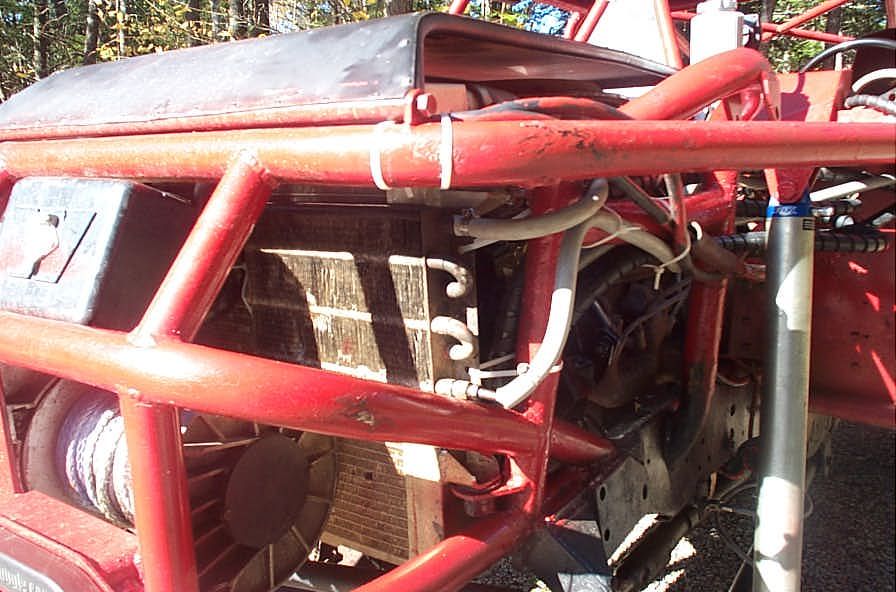
I mounted the reservoir back near the firewall where it could get some airflow for cooling. | ||||||||||||||||||||||||||||||||||||||||||||||||||||||||||||||||||||||||||||||||||||||||||||||||||||||||||||||||||||||
 |
I am going to investigate adding a larger reservoir soon, as I believe this small reservoir is barely adequate in terms of size. Recall from Part 2 that standard industrial system design practice is to specify a reservoir size of 2-3 times the gpm of the pump. In my case, the pump flows 3.7 gpm, making a min reservoir of over 6 gallons. Obviously that size is neither practical, nor required, as I am running only a single cylinder, rather than many cylinders or actuators for lifts, buckets, forks, rams etc. However, if you also recall from part 1, all of the many important functions of the reservoir, I feel that this reservoir alone, at only approximately 1/3 of a gallon to be inadequate in capacity. I say this because I have found that fluid level is extremely critical and that there is little (if any) reserve fluid capacity that the fluid is at risk of excessive turbulence, aeration, and foaming - all conditions a properly sized reservoir is designed to reduce. | ||||||||||||||||||||||||||||||||||||||||||||||||||||||||||||||||||||||||||||||||||||||||||||||||||||||||||||||||||||||
Pump |
|||||||||||||||||||||||||||||||||||||||||||||||||||||||||||||||||||||||||||||||||||||||||||||||||||||||||||||||||||||||
 |
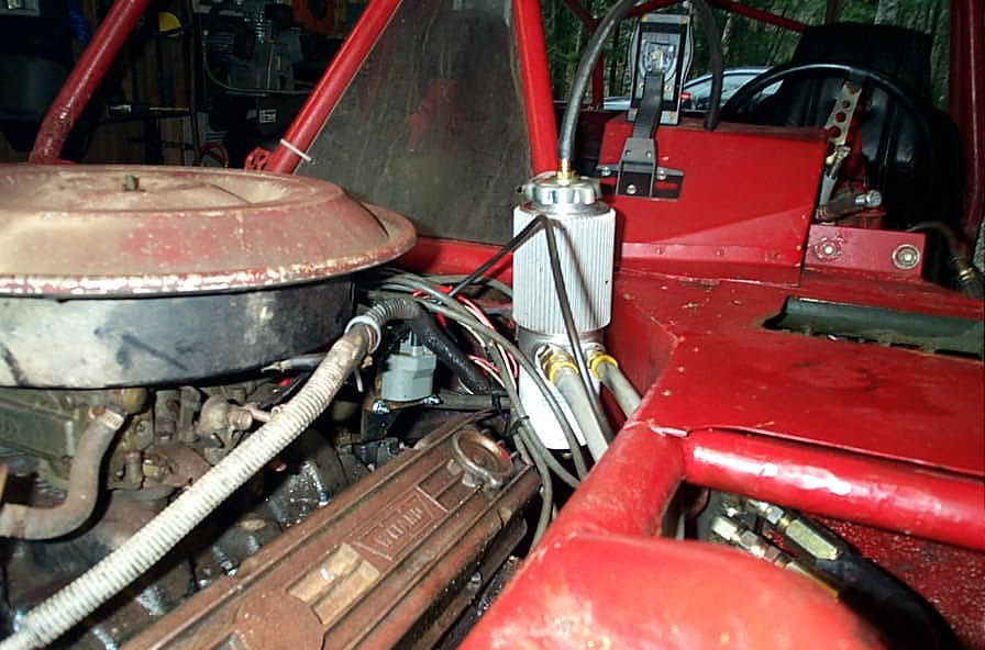
Here's the modified P-style Saginaw pump used in my initial system. Note the 5/8" suction line supplying fluid to the reservoir from the remote auxiliary cooler/filter/reservoir assembly. After struggling with some strange plumbing problems, the worst of which was the vented reservoir from Performance Off-Road Systems puking hydraulic fluid out the top of a 2' vent hose, that we couldn't fully troubleshoot before I lost my mind in frustration, I ended up replacing the pump and suction line, as well as deleting my Hydroboost brakes all in one go. |
||||||||||||||||||||||||||||||||||||||||||||||||||||||||||||||||||||||||||||||||||||||||||||||||||||||||||||||||||||||
 |
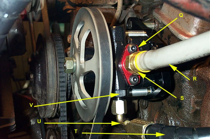
This is the KRC cast Iron pump with 6" Aluminum V-belt pulley I settled on. I mounted to to the left head of the 350 with the KRC bracket kit. | ||||||||||||||||||||||||||||||||||||||||||||||||||||||||||||||||||||||||||||||||||||||||||||||||||||||||||||||||||||||
 |
It is a very compact unit, that installed easily and very cleanly. I had to get a longer V-belt to run it, and makes some small custom spacers to mount the bracket to the head so that everything lined up perfectly (because of my non-stock water pump housing). | ||||||||||||||||||||||||||||||||||||||||||||||||||||||||||||||||||||||||||||||||||||||||||||||||||||||||||||||||||||||
 |
These pumps are high volume pumps with standard flow of 2.5 GPM. With the interchangeable flow valves the flow can be set anywhere in the range 1.5 GPM to 3.7 GPM. These units have the same pulley offset and mounting pattern as the GM Saginaw style pumps. They run at 1350-1450 psi, and I chose the highest flow of 3.7 gpm to feed my steering unit. |
||||||||||||||||||||||||||||||||||||||||||||||||||||||||||||||||||||||||||||||||||||||||||||||||||||||||||||||||||||||
PlumbingThis was a PITA, plain and simple. I was pretty much on my own, and ended up trial and error'ing my way through a bunch of stuff, buying way more than I needed, having to redo stuff more than once, ending up with a drawer full of used, useless fittings etc etc. Oh well - at last you can learn from my mistakes! Note: Originally I incorporated hydroboost brakes into my system. I had some big problems with my plumbing, extremely frustrating problems that I was unable to isolate or solve before cutting the entire hydroboost brake system out (in part because I suspected a faulty hydroboost booster) of the hydraulic circuit. The problem is, I may never know exactly what the problem was as I replaced some hoses and the pump itself all in one go - I was that frustrated. As such, this article will concentrate on a hydro steering system without any other hydraulic components (such as hydroboost brakes). If I ever return to hydroboost and sort out the plumbing I will update the article. The usual flow of fluid through the circuit will be: Reservoir --> Pump --> Steering Unit --> Cylinder -->Steering Unit --> Cooler and/or filter --> Reservoir. There are 3 types of hose you will be running in a hydro steering system: pressure hose, return hose, and suction hose. Each has a different requirement. The following table summarizes all the hoses and fittings I ended up using in my system. I used Parker hose and fittings, and also made a small pdf file of the appropriate Parker catalogue pages that show the hose and fittings I used. I even highlighted in yellow the parts that I used. You can view it by clicking below: (NOTE: In the catalogue, I highlighted the 801 Push-lok hose in 1/2" and the -10 JIC to 1/2" hose barb fittings, because that's what I actually used. However, I also highlighted the 821 Push-lok hose in 5/8" and the -10 JIC to 5/8" hose barb fittings. because in retrospect these would have been a better choice, being larger ID and still rated for a full 28" Hg Vacuum as a suction line. The reason I didn't use the 5/8" 821 was, my supplier doesn't stock it. This meant had to drop down to the 1/2" size in the 801 hose as this was the only way to retain the full vacuum rating of 28". This is important to your suction hose (pump supply) doesn't suck closed at higher RPM's. Bottom line - use the largest diameter suction line from reservoir to pump that you can, but MAKE SURE it is rated for a full 28" Hg (Ask me how I know !!) |
|||||||||||||||||||||||||||||||||||||||||||||||||||||||||||||||||||||||||||||||||||||||||||||||||||||||||||||||||||||||
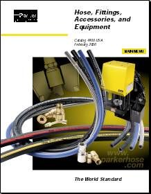 |
Parker Hose and Fittings used on the Wolf | ||||||||||||||||||||||||||||||||||||||||||||||||||||||||||||||||||||||||||||||||||||||||||||||||||||||||||||||||||||||
Browse the complete Parker hose and fitting catalogue at:Parker Hose & Fittings Catalog Custom making hydraulic hoses at home with field attachable fittings |
|||||||||||||||||||||||||||||||||||||||||||||||||||||||||||||||||||||||||||||||||||||||||||||||||||||||||||||||||||||||
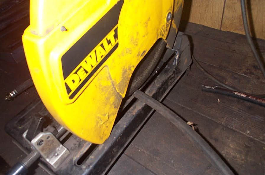 |
Cut the hose to length with a quality hacksaw or abrasive chop saw. | ||||||||||||||||||||||||||||||||||||||||||||||||||||||||||||||||||||||||||||||||||||||||||||||||||||||||||||||||||||||
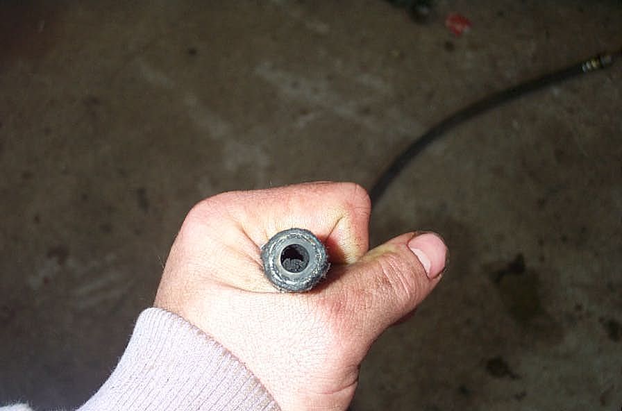 |
Be sure you clean out the debris from inside the hose after the cut, and then lubricate the inside of the hose with hydraulic fluid. | ||||||||||||||||||||||||||||||||||||||||||||||||||||||||||||||||||||||||||||||||||||||||||||||||||||||||||||||||||||||
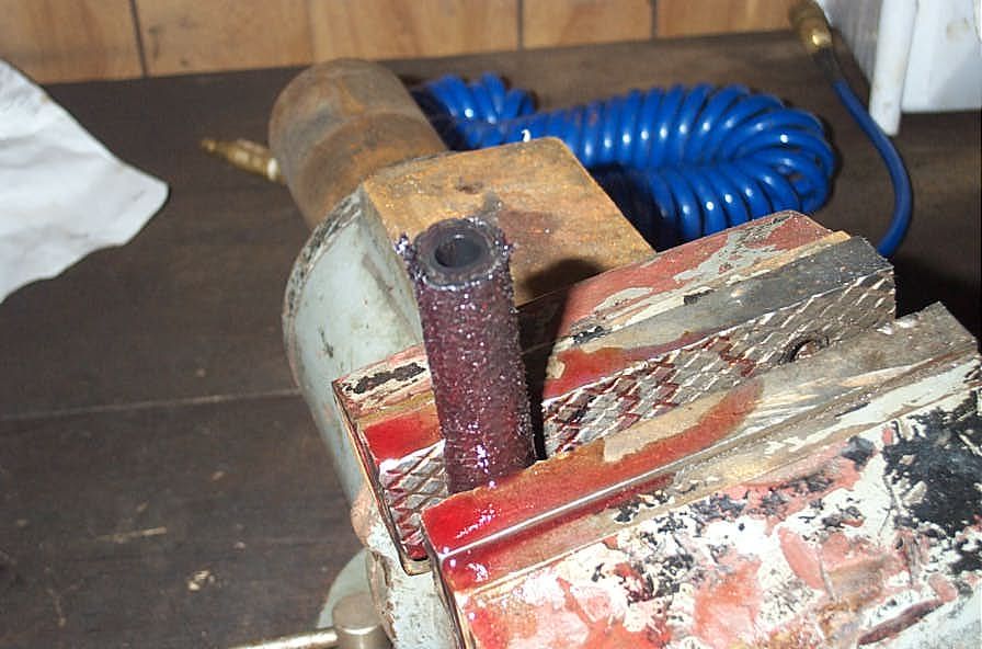 |
Clamp hose in vice. | ||||||||||||||||||||||||||||||||||||||||||||||||||||||||||||||||||||||||||||||||||||||||||||||||||||||||||||||||||||||
 |
Place socket over hose and screw on counterclockwise until it bottoms. | ||||||||||||||||||||||||||||||||||||||||||||||||||||||||||||||||||||||||||||||||||||||||||||||||||||||||||||||||||||||
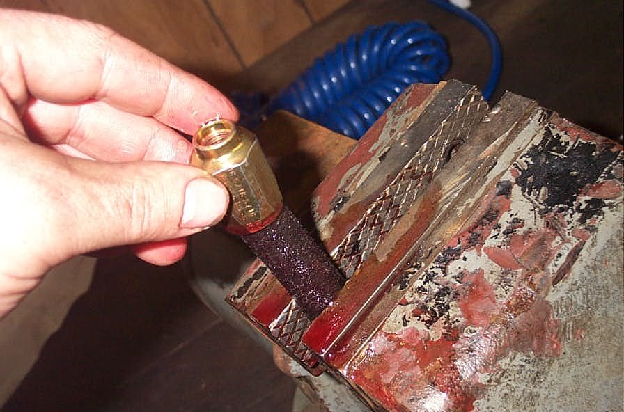
 |
Lubricate insert with fluid. | ||||||||||||||||||||||||||||||||||||||||||||||||||||||||||||||||||||||||||||||||||||||||||||||||||||||||||||||||||||||
 |
Thread insert into socket. | ||||||||||||||||||||||||||||||||||||||||||||||||||||||||||||||||||||||||||||||||||||||||||||||||||||||||||||||||||||||
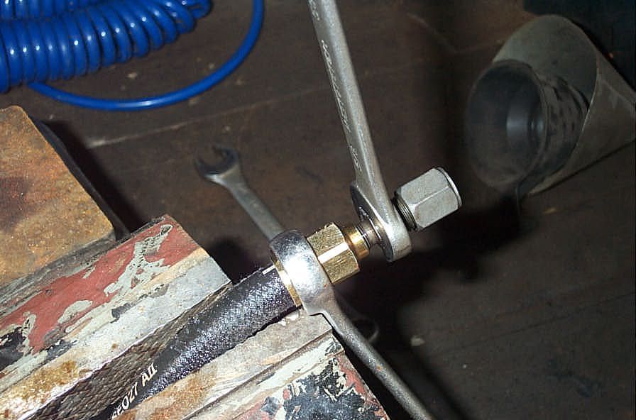 |
Tighten insert until it almost bottoms (leave about thickness of a dime between insert head and socket. | ||||||||||||||||||||||||||||||||||||||||||||||||||||||||||||||||||||||||||||||||||||||||||||||||||||||||||||||||||||||
Bleeding the system |
|||||||||||||||||||||||||||||||||||||||||||||||||||||||||||||||||||||||||||||||||||||||||||||||||||||||||||||||||||||||
 |
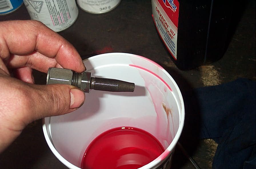
In preparation for the step of bleeding all the air from the system it is a good idea to pre-charge all of the components with fluid, as much as possible. I used a small funnel to fill the cylinder - it took almost half a quart! You can't get any fluid in the steering unit really, so that just leaves filling up the cooler if you can and of course the reservoir. | ||||||||||||||||||||||||||||||||||||||||||||||||||||||||||||||||||||||||||||||||||||||||||||||||||||||||||||||||||||||
 |
Once you have everything installed and plumbed, it's time to fill and bleed. The procedure I discovered works well is:
|
||||||||||||||||||||||||||||||||||||||||||||||||||||||||||||||||||||||||||||||||||||||||||||||||||||||||||||||||||||||
Complete SystemIn case you haven't seen enough, here are a few more pics of my system, as it stands right now. |
|||||||||||||||||||||||||||||||||||||||||||||||||||||||||||||||||||||||||||||||||||||||||||||||||||||||||||||||||||||||
 |
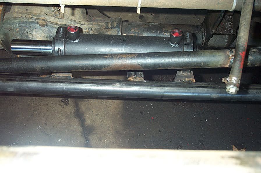
Cylinder and hoses. | ||||||||||||||||||||||||||||||||||||||||||||||||||||||||||||||||||||||||||||||||||||||||||||||||||||||||||||||||||||||
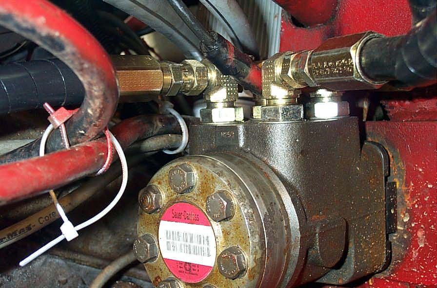 |
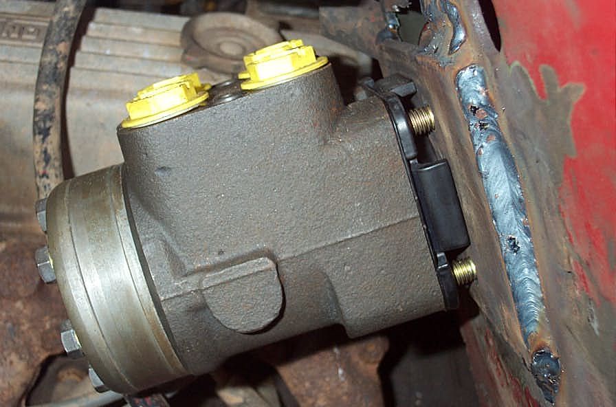
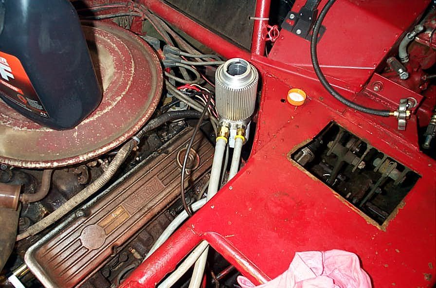
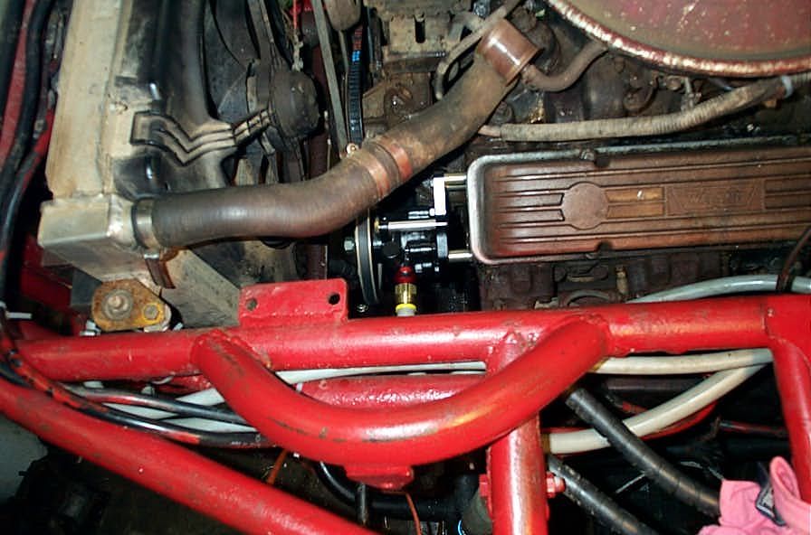
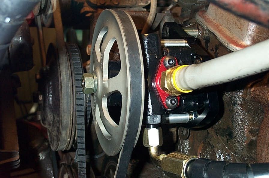
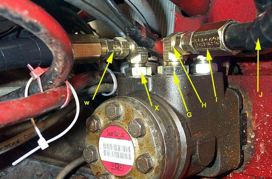
Mounted and plumbed Steering Unit. | ||||||||||||||||||||||||||||||||||||||||||||||||||||||||||||||||||||||||||||||||||||||||||||||||||||||||||||||||||||||
 |
Low Pressure "Push-Lok" connections at the Cooler/Filter/Reservoir. | ||||||||||||||||||||||||||||||||||||||||||||||||||||||||||||||||||||||||||||||||||||||||||||||||||||||||||||||||||||||
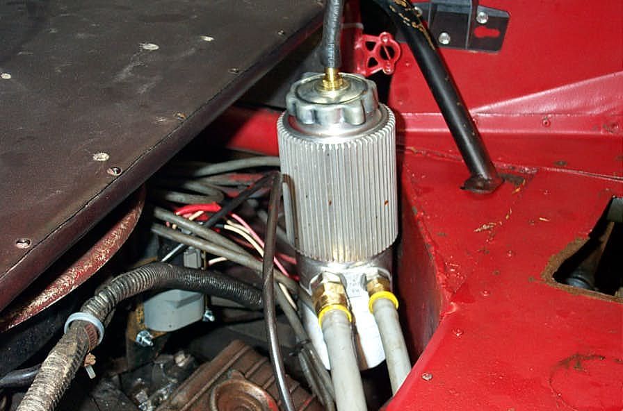 |
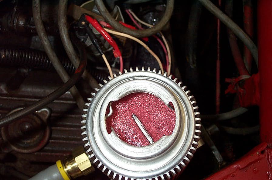
CFR mounted with vent hose on cap. | ||||||||||||||||||||||||||||||||||||||||||||||||||||||||||||||||||||||||||||||||||||||||||||||||||||||||||||||||||||||
 |
PS Pump mounted and plumbed. | ||||||||||||||||||||||||||||||||||||||||||||||||||||||||||||||||||||||||||||||||||||||||||||||||||||||||||||||||||||||
 |
Cylinder location. | ||||||||||||||||||||||||||||||||||||||||||||||||||||||||||||||||||||||||||||||||||||||||||||||||||||||||||||||||||||||
 |
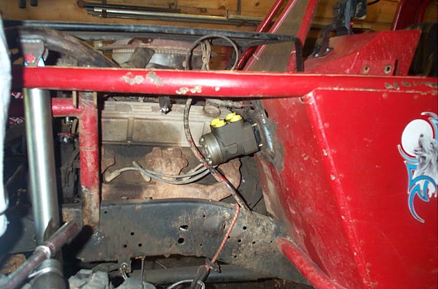
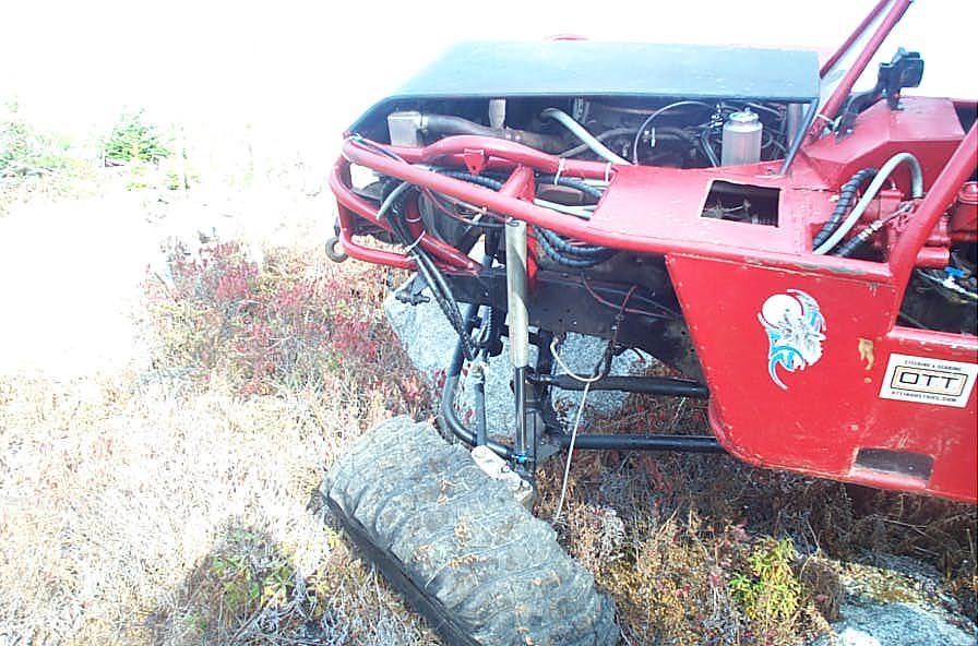
Steering is high and well protected. | ||||||||||||||||||||||||||||||||||||||||||||||||||||||||||||||||||||||||||||||||||||||||||||||||||||||||||||||||||||||
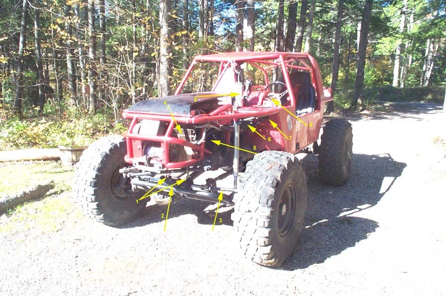 |
|
||||||||||||||||||||||||||||||||||||||||||||||||||||||||||||||||||||||||||||||||||||||||||||||||||||||||||||||||||||||
PerformanceAT LAST - This is the most important bit, right? I am THRILLED to report it is everything I had hoped it would be and more. Not only that, but none of the negative things I had read were even remotely true either! First - what it isn't. All the tings you may have read, certainly that I had read, about hydro steering, all the negatives and drawbacks - none were true of my system. The steering wheel returns to center fine after a turn. There is plenty of "road feel' both at speed and in the rocks. It is not "squirrely at speed", at least not up to 45-50mph, despite being approximately 2.5 turns lock-to-lock. It doesn't wander, there is no fade, and, when plumbed properly and with all the components in top shape (no crapped out old pump or malfunctioning hydroboost booster or improperly rated suction hose sucking closed at high rpm - all mistakes I made of course!) it is cool and quiet. I attribute this to the fact that the components themselves and in particular the system is designed for my specific application. The steering unit has the proper displacement for my pump and turns lock-lock desired. My new pump produces the appropriate flow and pressure, hoses are properly specified and sized, cylinder is custom built for purpose, etc etc. I believe a lot of the "negative" feeling and opinion / experience you may read about "out there" on the net comes from the early days of guys pioneering the idea of 4x4 hydro steering (no offence to them - they did us all a service) with used, mismatched, parts scavenged from broken combine harvesters and wrecked forklifts and such. As you are now fully aware - this can lead to all manner of wacky results - you need only review the section in Part 2 about system design to understand this. I am pleased to report that none of these faults are present in my system. Second - what it is. Quite simply - the best steering I have ever experienced, on ANY vehicle I have ever owned or driven, with the exception of an extremely expensive sports car I rented once at one of those fantasy places. Not only can I now steer my welded and slugged, 38" @ 5 psi shod Dana 60 sitting still on the rocks LOCK to LOCK with just one finger...but the feel and response at (moderate) speed is unbelievable! There is no slop at all At speed, (granted, we're only talking up to 40-50 mph here, as that is as fast as I have driven the Wolf) it is tight and precise. I'd never driven a 4x4 with a slop-less steering system before - usually a huge amount of the slop is the hallmark of a 4x4. Not so anymore. Being a fluid power system, there are no gears requiring backlash, and with the only joints being the rod ends between cylinder and steering arms, and those being brand new ptfe lined units, there is simply no slop in the system. This alone makes it a joy to drive again. But the real thrill is in the rocks and over the tough stuff |
|||||||||||||||||||||||||||||||||||||||||||||||||||||||||||||||||||||||||||||||||||||||||||||||||||||||||||||||||||||||
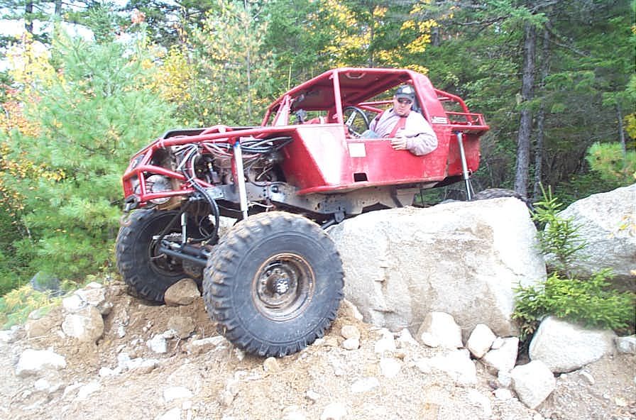 |
This was the first obstacle on the first trail on my first ever day of testing. At this time I didn't have the tie-rod / steering arm geometry right, the presumed dysfunctional hydroboost booster was still plumbed in the system, and the old worn out pump was running the show. As a result the reservoir was puking fluid out the vent hose and into a catch can bungee tied to the hood. Even with those limitations, the steering was superb. In this pic, with the old steering gearbox setup, and with me being in welded front low-low with drive slugs in the hubs, steering in a situation like this would have been impossible. I'm just about high-centered, and the front tires are over but still up against the rock while the rear tires are just meeting the back side of the rock. With forward progress stopped, steering the old fashioned way would be impossible. Not only that, but I would have been forced to dismount and press the winch into service. |
||||||||||||||||||||||||||||||||||||||||||||||||||||||||||||||||||||||||||||||||||||||||||||||||||||||||||||||||||||||
Not so with my new hydro steering. Even in a situation like this, with no forward progress, essentialy stuck, with welded fromt diff, I could easily steer back and forth with only 2 fingers and the engine just idling. In the end I was able to just wiggle the steering back and forth from this position, grab some traction, and pull my self over the boulder. Actually, that was an unexpected by very cool advantage to the mod - I never thought of hydro steering as a traction aid, but throught my expereince and testing so far i have found many times that the ease of steering allowed me to wiggle around and find traction in situations that before would have left me hung up and looking for a yank or winch. VERY COOL! |
|||||||||||||||||||||||||||||||||||||||||||||||||||||||||||||||||||||||||||||||||||||||||||||||||||||||||||||||||||||||
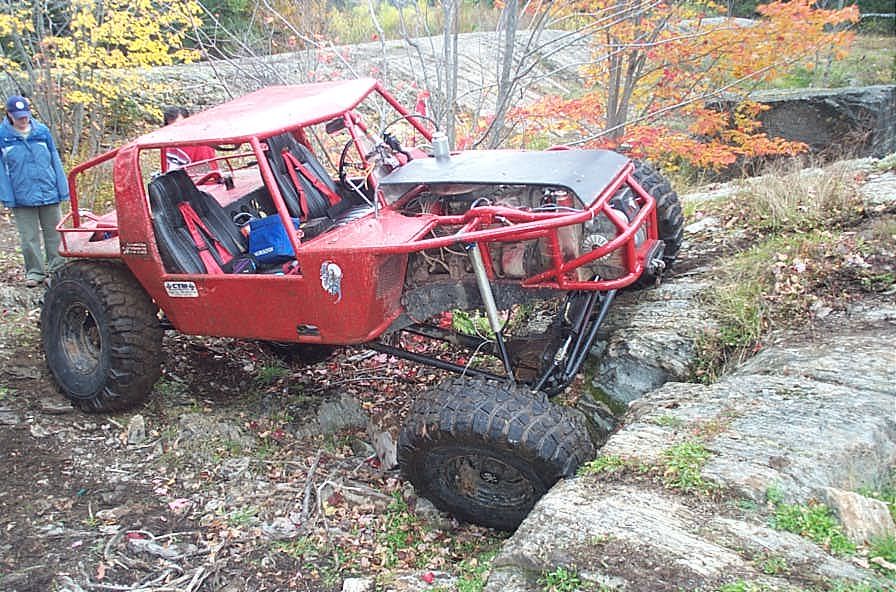 |
Even while scraping the diff and axle tube over rocks the steering remains well protected. And again, in this spot, with the passenger front in a hole and up against the rock, I was easily able to steer back and forth to find traction. | ||||||||||||||||||||||||||||||||||||||||||||||||||||||||||||||||||||||||||||||||||||||||||||||||||||||||||||||||||||||
 |
In this spot I drove up with the steering cranked hard to the right, and let the suspension fully twist up. Leaving the engine idling in neutral with the rear line lock on I was able to hop out and crank the wheels from lock to lock with 2 fingers standing beside the rig. | ||||||||||||||||||||||||||||||||||||||||||||||||||||||||||||||||||||||||||||||||||||||||||||||||||||||||||||||||||||||
 |
And I can fully attest to the manual steering capability of my Danfoss steering unit. I killed an alternator, a battery, and a coil in one trip (bad day electrically!) which lef me on the strap behind Chad's YJ the whole way out. It wasn;t easy or comfortable, but it works. | ||||||||||||||||||||||||||||||||||||||||||||||||||||||||||||||||||||||||||||||||||||||||||||||||||||||||||||||||||||||
|
|||||||||||||||||||||||||||||||||||||||||||||||||||||||||||||||||||||||||||||||||||||||||||||||||||||||||||||||||||||||


 |
Sources: Sean
Stapley 1712 Indian Pines Rd. Wetumpka , Al 36093 Phone: 334 567 7229 Fax: 334 567 7220 |
|