 |
Race Comms
By Bill "BillaVista" Ansell |
IntroductionSo you want to turn your wheeling rig into a racer, eh? Cool. Now, one of the most important things Wait! "Most important?" you ask. How can that be - what about a bigger motor, better No. It isn't. And that's because comms is what the military call a "force multiplier", that is, |
 |
Let me explain. The right comms system, which includes the right hardware properly installed, the knowledge and ability to use it, and an effective plan for its use, has many beneficial effects on your racing effort. For example:
All of these are big enough advantages, but the biggest comes from the combination of radio and intercom in the car, greatly simplifying in-car communications between driver and codriver. With a quality comms setup you can achieve excellent clarity of communications between the two - this means no more misunderstandings (" I thought you said left?") which is a huge boost to how well the car is driven. Clear and effective comms also plays a significant role in reducing fatigue which again, boosts performance. Of course, all of these factors work in reverse if you are without decent comms, and worse - if your setup is poor, trying to manage comms can quickly lead to increased workload, frustration, and ultimately a poorer performance. So here's how to get the good and avoid the bad. Table of Contents |
|
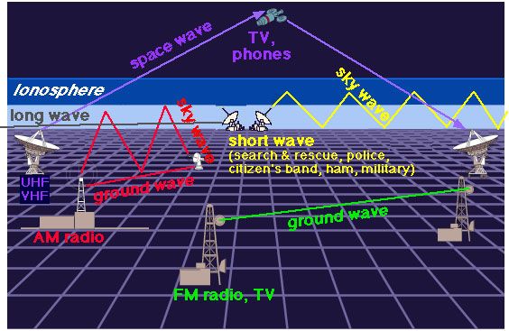
Waves & The EM SpectrumRadio theory, antenna theory, electromagnetic propagation - all are advanced, complicated topics. I'm going to keep it short and sweet and try to cover only what you need to know to intelligently choose, install, and operate a race car comms system. But we do have to cover a bit - because if you don't know a wavelength from a frequency, or UHF from VHF, you're going to be at a bit of a disadvantage. We'll start with some basic wave form physics and the electromagnetic (EM) spectrum - don't worry - it's mostly harmless. Two-way radios (that is, radios that can transmit and receive, allowing you to communicate) work by transmitting and receiving radio waves. Radio waves are a form of electromagnetic energy that are generated by one radio, transmitted by that radio's antenna, travel (or propagate) through the air, are intercepted (received) by another radio's antenna, and can then be heard on the receiving radio. The following diagram depicts many different types of radio waves and their uses.
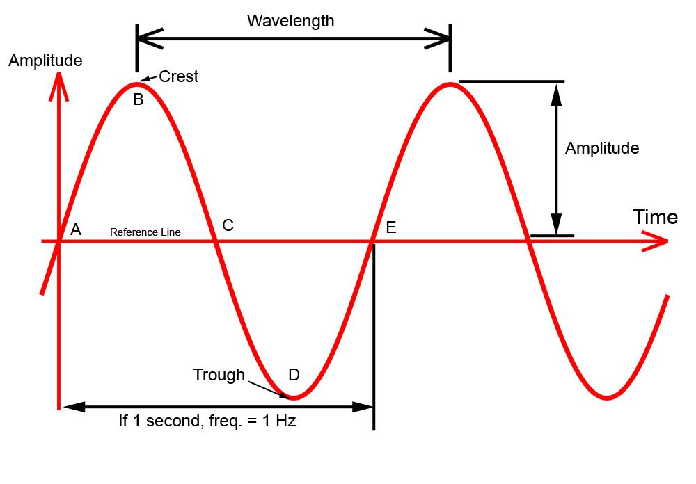
Waves transfer energy from one point to another without transferring matter. They consist of disturbances which transfer the energy in the direction the wave travels without transferring matter. A radio wave is a very complex form of EM energy containing both electric and magnetic fields that interact in complex ways with the Earth's atmosphere. The study of them is a whole branch of complicated physics. In order to keep this article to a reasonable length, and to keep the appeal as broad as possible, we're going to skip over a lot and just hit some highlights - so no letters from the physicists please! Properties of Radio WavesThe basic shape of the wave generated by a radio transmitter is that of a sine wave.
A sine wave, as illustrated in this pic, has the following characteristics: CycleA continuous sine wave is composed of several repeating parts called "cycles". Points ABCDE comprise one complete cycle having a maximum value above, and a maximum value below, the reference line. The maximum value above the line is referred to as the TOP or CREST, and the maximum value below the line is called the BOTTOM or TROUGH, as depicted in the figure. Therefore, one cycle has one crest and one trough. WavelengthA wavelength is the distance in space occupied by one cycle of a radio wave at any given instant. If the wave could be frozen in place and measured, the wavelength would be the distance from the leading edge of one cycle to the corresponding point on the next cycle. Wavelengths vary from a few hundredths of an inch at extremely high frequencies to many miles at extremely low frequencies; however, common practice is to express wavelengths in meters. The distance between A and E is one wavelength. AmplitudeTwo waves may have the same wavelength, but the crest of one may rise higher above the reference line than the crest of another. The height of a wave crest above the reference line is called the amplitude of the wave. The amplitude of a wave gives a relative indication of the amount of energy the wave transmits - in other words the signal's strength.. FrequencyWhen a continuous series of waves passes through a medium (like air), a certain number of individual waves pass a given point in a specific amount of time. The number of cycles of a continuous wave per unit of time is called the frequency of the wave and is measured in Hertz. One Hertz (abbreviated Hz) is one cycle per second. Therefore, if 5 waves pass a point in one second, the frequency of the wave is 5 cycles per second or 5 Hz. One frequency with which we are all familiar is the frequency of normal household electrical current. In North America, this is 60 Hz. In the study of radio waves, the frequencies can get very high, so in addition to Hz we also use the units kilohertz (one thousand hertz) megahertz (one million hertz), and gigahertz (one billion hertz). 1,000,000 Hertz (Hz) = 1000 kilohertz (KHz) = 1 megahertz (MHz) = 0.1 gigahertz (GHz). Frequency and wavelength are related to one another by the following simple equations:
and
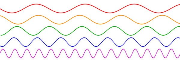
where the speed of light = 299 792 458 meters / second (roughly 300 million m/s ) Most often we talk about radio waves by frequency. A quick and dirty method to approximate the wavelength of a given radio frequency is to divide 300 by the frequency in MHz to get the wavelength in metres. For example, if Race Ops transmit on a frequency of 151.490 MHz, the wavelength of their transmissions is 300 / 151.490 = 1.980 metres (or about 2 metres). The following diagram illustrates waves with the same amplitude, but different wavelengths and therefore also different frequencies:
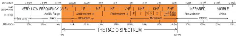
Frequencies between 3000 hertz (3 KHz) and 300,000,000,000 hertz (300 GHz) are called radio frequencies since they are commonly used in radio communications. This part of the EM spectrum is divided into bands, each band being 10 times higher in frequency than the one immediately below it. The radio frequency bands are shown in the following table. Radio Frequency Bands
Here's a look at where these radio frequencies fit in the overall EM spectrum.
Why is all this talk of wavelength and frequency important? Well, for the average user, it comes down to two things - range and clarity. That is - how far can I reach with my radio? And how clear will it be? The answers to these two questions depend on a lot of complicated inter-related factors - from power to antenna tuning to sun-spot activity and the curvature of the earth. But, the factors we can easily control that most affect range and clarity are wavelength (and therefore the frequency) and the power output of the radio. We'll cover these in more detail as they apply to choosing and buying a radio in a moment, but first we must briefly introduce the concepts of theoretical range, attenuation, and "line of sight". The wavelength of the radio wave has a huge effect on the range and clarity that can be achieved. In very simple terms, the longer the wavelength, the lower the frequency, and the greater the range. The physics behind why this is so are not terribly important to understand so we'll just accept it as fact. If it helps, imagine you have a rope between two people which you intend to use to send a signal between them. Imagine you intend to send that signal by flicking one end of the rope so as to send a wave down it. The longer the rope, the further your signal can reach, but the weaker it will be when it gets there (poorer quality). There's all kinds wrong with that analogy, so to keep me from going on for pages and to keep the physics boffins off my back, just remember that in general:
In the typical "nothing is free" nature of the universe, typically the longer the wavelength the poorer the quality of the signal and therefore the less clear it is. Think of a movie where you've seen military radio operators communicating over great distances, particularly over the horizon from one another (also known as "beyond line of sight or BLOS). The reception is spotty and full of static. There are delays, interference, and lots of "noise". Quality is poor and the operators speak in that funny sounding strict military way to make sure they are heard and understood. This is because, in order for the radio waves to transmit that far, they have to be long wavelength (low frequency) - typically in the HF range. Now, imagine a modern cellphone operating in the GHz frequency range - very short wavelength, very high frequency. Quality and clarity is excellent, but range is very poor - which is why you have to be within range of a "cellphone tower" to have service, and why the towers must be so high. So now we have:
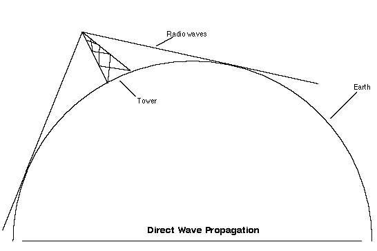
Which brings us to the concept of "line of sight" range. What this means is that, theoretically, for radios that operate in the frequency range we are interested in (typically VHF and UHF), quality is very good, but because of the short-ish wavelengths, range is limited to direct line of sight (LOS) - that is, there must be an unobstructed path directly between the transmitting antenna and the receiving antenna. The direct LOS for two objects on the surface of the earth, providing there are no obstructions between them, is about 5 miles before the curvature of the earth gets in the way and begins to obscure one from the other. This is where antenna height comes into play - just like for the cell tower. It is easy to imagine that LOS is going to be a lot further if two people were perched at the top of two mountains than if they were sitting on surfboards on the ocean. On land, in other terrain, obviously this theoretical LOS range can very from several miles to mere feet. The following diagram illustrates the concept of LOS transmission and the advantage of antenna height.
The equation for max theoretical range is: R = 1.4*(Sqrt(Ht) + Sqrt(Hr)) Where: R = the range in miles Ht = the height of the transmitting antenna in feet Hr = the height of the receiving antenna in feet So if your antennae are 6' off the ground, max theoretical range is about 1.4*(Sqrt(6) + Sqrt(6) = 6.8 miles But if they are 500' off the ground, max range increases to: 1.4*(Sqrt(500) + Sqrt(500) = 62 miles (assuming there are no obstructions). That's the theoretical maximum range. In practice, the propagation characteristics of these radio waves vary substantially depending on the exact frequency and the strength of the transmitted signal (a function of both the transmitter and the antenna characteristics). In reality, there are factors that can both add to and subtract from this range. Factors that reduce the range include:
Factors that increase range include:
The different radios we can buy and use are susceptible to these factors to a greater or lesser degree depending on the radio, and we'll cover how shortly. Of course, there are reasons other than these that may influence or even wholly dictate the choice we must make in terms of radio frequency band - chiefly what frequency do we need to use to be able to communicate with others? Once a radio that works in a particular frequency band is chosen, the key to getting more range is to either raise the height of the antenna, increase the power of the radio, or both. |
|||||||||||||||||||||||||||||||||||||||||||||||||||||||||||||||||||||||||||||||||||||||||
Two-way Radio BasicsOK, so we've covered the basics of radio waves so that we can now cover the basics of two-way radios - like those used used in off-road race cars. We're all familiar with the type of radio we have in our daily driver cars. They operate using the same radio waves as we have described above. The difference is, they are receivers only - they receive the radio waves transmitted or "broadcast" by the radio station (which, for reasons we now understand, use tall antenna towers and high power). But they cannot transmit - so not very useful for two-way communications. A two-way radio, on the other hand, can both transmit and receive. Generally, two-way radios (hereafter referred to simply as "radios") , come in one of three flavours:
They all work the same way, but as we progress from hand-held up to stationary size, weight, power, and antenna size increase (and therefore range). Clearly, each has its specific purpose. The rest of this article shall concentrate on hand-held and mobile models as these are the most useful to racers (even your "camp" or pit is rarely truly stationary). If you've ever used a CB radio or a walkie-talkie then you're already familiar with the basic features and method of operation of a race radio - they work in essentially the same way. Common features include:
Handheld portable radios are designed for short-range communication between people or between a person and a mobile radio. They prioritize portability over range and therefore have small antennae and limited battery power. In the United States the Federal Communications Commission regulations state that handheld radios are limited to no more than 5 watts of power. Vehicle-mounted mobile two-way radios mount in a car or truck and are wired into the vehicle's electrical system for power. They have greater power and a larger external antenna mounted on the vehicle. Power is normally in the 50-100 watt range for a typical race radio. Desktop base station radios use wall AC power and an external-mounted antenna, often mounted on top of a building or even on a tower to increase range. Mobile radios can be used as base-station radios by connecting them to a convenient DC power source (a spare car battery) or by using an AC to DC power converter. Modulation and TransmissionOK, so radios use amplifiers and antennae to transmit electromagnetic energy (radio waves) back and forth through the atmosphere. But how does this let me talk back and forth with another radio user, and why do I care how it works. The answer to the second question is, because you have to know what type of radio you need - and one of the main differences between radios is something you're already familiar with - some are AM, some are FM, just like the radio in your daily driver car. We need to understand the difference between AM and FM for one of two reasons. Either:
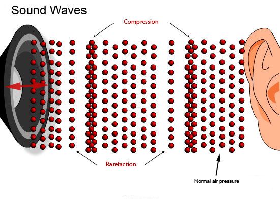
And to understand the difference between AM and FM, we must first understand what modulation is (that's what the "M" in AM and FM stands for). And understanding modulation is the answer to how a radio actually lets you talk back and forth. Here's the super quick and dirty version of how it all works. Sound, produced by your voice (or your home theatre speakers), consists of physical vibrations in the air. If you could see the actual air molecules, you would see that they alternately bunch up together (a compression) and get spread out (a rarefaction). These are sound waves, created by the movement of your vocal chords, a stereo speaker's cone, or anything else that can compress air and therefore create sound. These sound waves also have frequency - ranging from 20Hz (deep bass) to 20 kHz (high treble). Human speech occurs in the 80Hz - 3 kHz range. In the case of simple communication through normal speech and hearing, one person's vocal chords create the sound waves, they travel through the air and vibrate the listeners eardrum back and forth which turns the sound waves into impulses the brain can read. Simple.
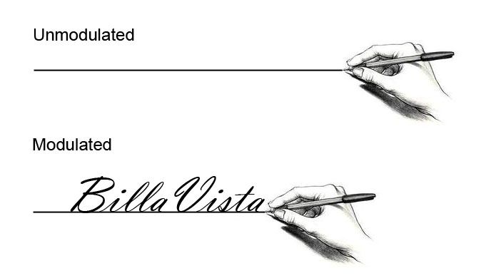
When we introduce a radio to extend the range of communication, things get a little more complicated. Now, when the speaker speaks, the sound waves they create vibrate not an eardrum, but a thin membrane in the microphone. The microphone translates these vibrations into electrical impulses. These electrical signals are the sound, called the "information", that needs to get carried to the speaker of the radio on the receiving end so that they can operate in reverse and cause the speaker cone to vibrate back and forth, creating sound waves again, that then go on to vibrate the listener's ear drum. The "information" we want to send via radio (e.g. someone's voice) is called the baseband signal. So we have information that needs to be carried somewhere. This is where modulation comes in. Just like a letter needs a postman to carry it to its destination, so the sound information needs a carrier to carry it to the receiving radio. Only instead of using a guy with a mail bag, we use electromagnetic energy waves - radio waves. With me so far? Good. This is where modulation comes in. Modulation is simply a fancy word for changing something in order to encode it with information. In this case, modulating a carrier wave so that it is encoded with a baseband signal (sound information) that can be demodulated at the receiving end and the information, or sound, decoded and sent to the speaker and thence the listener's ear. A simple form of modulation is to think of a pen drawing a straight line across a piece of paper. The straight line is unmodulated, it carries and transmits no information. However, if you modulate (change / vary) the line by writing, then the line carries and transmits information.
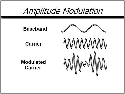
Back to radios. Recall that radio waves have both frequency and amplitude. Radio waves, like other waves, are measured by frequency, the number of times a wave varies above and below a reference point. In addition to frequency, radio waves also have amplitude. Amplitude describes the height or intensity of a given wave. The ability to manipulate variations in amplitude and frequency makes possible the modulation of the carrier radio wave. In other words, we modulate, or change, the frequency or the amplitude of the carrier wave, and by doing so we can code it with the information, (baseband signal) we wish it to carry. Thus, we have AM or "amplitude modulation" radio and FM or "frequency modulation" radio waves. AM vs. FMAM (amplitude modulation) varies the amplitude (intensity) of the carrier, while the frequency remains the same.
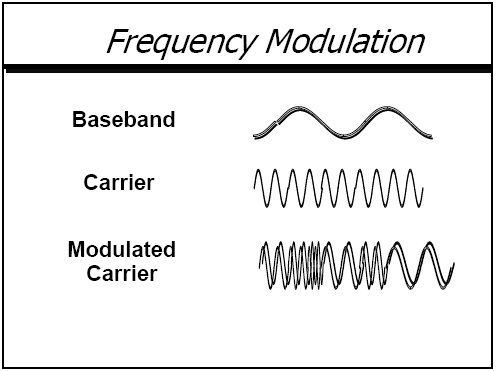
FM (frequency modulation) encodes the sound information by changing the frequency, while the amplitude remains constant.
This figure shows a simple baseband or signal sine wave, followed by a representation of what it might look like modulated by amplitude and by frequency, (AM and FM).
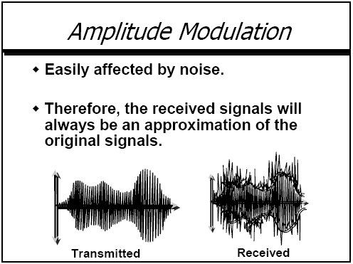
Each method has its advantages and disadvantages, with one of the most important differences being the amount of bandwidth the chosen method consumes in the process. That is, how much of the EM spectrum is need to convey the modulated signal that consists of the combination of the information (the baseband signal) and the carrier signal. A precise description of the different modulation methods is beyond the scope of this article, so I'll just summarize some of the important differences. Keep in mind that these are generalizations and not absolutes. AM is the oldest and simplest form of modulation. AM is a well established and mature technology. AM is easy to generate, easy to demodulate, and consumes less bandwidth than FM. It can be done using low power and relatively cheap and simple equipment. However, AM is very sensitive to noise contamination (noise is any EM signal that is not wanted - like static). Because AM transmission varies the amplitude of the wave, and static interacts with the amplitude of radio waves, AM is more susceptible to interference from other EM energy which further contributes to reduced quality and reduced fidelity of the sound. That's the scratchy, crackly part of AM radio on your car stereo.
AM is also limited by regulation and industry practice in that it is generally used for lower frequency transmissions - which means it generally has longer range than FM, but because of the resulting lower bandwidth allocated, isn't able to send as much information. That is, AM is unable to carry the full range of frequencies needed to reproduce high fidelity sound like music. Ever notice how most AM radio stations are all news, talk or sports (or really crappy music)? This is less of a problem with voice-only radio as in two-way radio use. FM is far more complex than AM. This means it requires more complex and expensive equipment (the modulation and demodulation are far more complex). Because the frequency is being changed, an FM signal consumes much more bandwidth than an AM signal - on the order of 10 to 20 times more. This greater bandwidth has its own pluses and minuses. On the plus side it means FM can support the transmission of more baseband frequency components, i.e. more information, higher fidelity sound. For example, commercial FM radio stations are each allocated a 180 kHz bandwidth which allows them to support a maximum baseband frequency of 15 kHz. On the other hand, commercial AM radio stations are each assigned to a 10 kHz channel which only allows them to support a maximum baseband frequency of 5 kHz. Recall that human hearing ranges from 20Hz to 20KHz and we see that better sound can be heard on FM (although voice-only communication doesn't really suffer from AM's lack of bandwidth). On the down side it also means that FM channels must be "wider" and therefore there are fewer of them in a given block of the EM spectrum (which can be a problem in the highly congested EM spectrum of today). By regulation and industry practice, FM transmissions are often (but not always) at higher frequencies (VHF & UHF) than their AM counterparts (HF & lower VHF) and thus even more limited to line of sight ranges than AM. Although more complex in design, FM offers better resistance to the effects of noise since it varies the frequency of the signal keeping the amplitude constant and therefore the modulation is not as susceptible to interference or being distorted. When a radio has more signal and less noise, we say it has a better signal-to-noise ration or greater SNR (you may have seen this term in radio or stereo specs). Ultimately, because of its greater bandwidth and better SNR, FM generally produces higher quality signals and therefore better quality sound. This following table illustrates a summary of the differences between AM and FM.
* - these characteristics are not strictly due to the modulation method alone, but are due to the frequencies commonly used with the type of modulation by convention, government regulator assignment, standard OEM design, or law. Two-way radio frequenciesSo, we've already touched on different frequencies. Let's take a brief look now at more specific radio frequencies. Two-way radios can operate on many different frequencies, and these frequencies are assigned differently in different countries.
Typically different frequencies are "channelized" - that is, a specific frequency is assigned a fixed channel number for a given type of radio, so that operators need not tune equipment to a particular frequency but instead can use one or more channels pre-set with the frequency, easily chosen by a push-button or other means. It is, for instance, easier to remember "Channel 1" than to remember "26.965 MHz" (CB Channel 1) or "156.05 MHz" (Marine channel 1). It is, of course, necessary to identify which radio service is under discussion when specifying a frequency by its channel number. This is a list of international Maritime channels The performance of a radio system is partly dependent on the characteristics of the frequency band used. The selection of a frequency for a two-way radio system is affected, in part, by:
This chart depicts frequency allocations in the United States. Note how incredibly "crowded" the EM spectrum is! Each country allocates radio frequencies to different two-way services, in accordance with international agreements. In the United States some examples of two-way services are: Citizen's Band (CB radio) , FRS, Marine, etc. This is an excellent article on frequency allocations. The following chart depicts some popular two-way radio services and their frequency allocations. 150 - 162 MHz: FM @ 15 kHz steps 150.815 - 150.965 Auto Emergency 150.995 - 151.595 Highway / Forestry / Industry 151.625 - 151.955 Business (30 kHz steps) 152.030 - 152.240 Mobile phone (Base) / Page (30 kHz steps) 152.270 - 152.450 Taxi (Base) 152.510 - 152.840 Mobile phone (Base) / Page (30 kHz steps) 152.870 - 153.725 Industry 153.740 - 154.445 Fire / Govt (mobile) 154.452 - 154.482 Industry (telemetry) (7.5 kHz steps) 154.490 - 154.625 Industry 154.650 - 156.240 Police / Govt / Emrgncy / Hwy 156.025 - 157.425 Maritime (ship) (25 kHz steps) 157.470 - 157.515 Auto Emergency 157.530 - 157.710 Taxi (mobile) / Business 157.770 - 158.100 Mobile phone (mobile) / Page (30 kHz steps) 158.130 - 158.460 Industry 158.490 - 158.700 Mobile phone (mobile) / Page (30 kHz steps) 158.730 - 159.210 Police / Govt / Highway 159.225 - 159.465 Forestry Conservation 159.495 - 160.200 Transportation - bus, truck 160.215 - 161.610 Railroad 160.625 - 160.950 Maritime - Coast (25 kHz steps) 161.640 - 161.760 {Broadcast Pickups
161.500 - 162.025 {Maritime - Coast (25 kHz steps)
UHF versus VHFThe two frequency bands most commonly used for two-way radios of the type we are interested in are VHF and UHF. Neither frequency band is inherently better than the other. Both formats are effective ways to communicate with another person so the right radio depends on the application. As we have learned, the frequency also determines the wavelength, and the wavelength has a big impact on radio performance. While both VHF and UHF are "line of sight" radios in theory, anyone who has used a two-way radio knows that in practice, it is possible to communicate with someone you can't see. The exact reasons are very complex, suffice to say that radio waves can penetrate certain solid barriers, they can also bend around obstacles, and "find there way through" obstacles (like trees) that are tightly spaced but not solid. How effectively they do this is largely a factor of the wavelength. Of course, greater power increases range for any wavelength, to a point (as does a properly sized and tuned antenna). VHF has a longer wavelength and as a general rule a VHF radio signal travels a greater distance. Lower frequencies (or longer wavelengths) have greater penetrating power. On the other hand, UHF has a shorter wavelength which makes it easier for the signal to find its way through rugged terrain and around obstacles. Imagine we are separated from the radio we wish to talk to by some mixed terrain with rocks and trees. Imagine the gaps between the trees are 3 feet wide. Imagine we are using a VHF radio transmitting a wavelength of 5 feet, and UHF radio transmitting a wavelength of 1.5 feet. The longer VHF wave will penetrate the trees and rocks better, but will not find its way through the trees as well since the wavelength is longer than the gaps between the trees. On the other hand, the UHF radio will have less penetrating power to get through the trees and rocks, but the signal will find its way around the trees and obstacles better since it is less than the gap between the obstacles. Imagine the wavelength is like a 2x4 strapped across your shoulders - if it's 5' long you can't fit between the trees, but if it's only 1.5' long, you can. Remember, both signals attenuate (loose strength) the further they go, and the more obstacles they encounter and get reflected off, refracted (bent) off, and absorbed by. Now, in a different scenario, imagine there are obstacles such as large boulders that are about 3 feet in diameter. Since they are larger than the UHF wavelength, they will block the UHF signal when it encounters them. Conversely, the larger 5 foot VHF wavelength, being larger than the boulders, will get around them better. The shape and composition (density) of obstacles have a large affect on how radio waves interact with them too. Smooth, rounded objects tend to deflect signals, whereas flat surfaces tend to reflect or absorb them. Dense materials such as metal tend to reflect signals, less dense material such as wood tend to absorb signals or let them pass, depending on the wavelength and power of the transmission. However, if a VHF wave and a UHF wave were transmitted over an area without barriers, the VHF wave would travel almost twice as far. There are more available channels with UHF so in more populated areas UHF may be less likely to have interference from other systems. Since the range of UHF is also not as far as VHF under most conditions, there is less chance of distant radios interfering with your signal. One other advantage of the short wavelength that is produced by the higher UHF frequency is that the antenna on the radio can be shorter than an equivalent VHF radio. That can make it more convenient in certain installations or to carry around as a portable radio. Since VHF has been around longer and isn’t as complicated to make, equipment can be cheaper when compared to similar UHF equipment. Simplex versus DuplexOne last thing we should discuss because you may come across it when researching radios is the difference between simplex and duplex operation. Simplex systems use a single frequency (channel) for both transmit and receive. This means you can't transmit and receive simultaneously - in other words, you can't talk and listen at the same time - you have to be doing one or the other. Most often, a push-to-talk (PTT) switch is activated to transmit, and then released when you want to listen. This is also known as "keying the mic"(rophone) when you want to talk. The thing is, whomever you're communication with has to do the same, in coordination with you. That is, if you both key the mic and try to talk at the same time neither of you will hear the other. This situation is handled by the use of certain "pro words" such as "over" so that both parties can work in sync. A duplex system, on the other hand, transmits and receives on different frequencies. A half-duplex system still requires the use of a PTT switch and operates much the same as a simplex radio. A full-duplex system however can both transmit and receive simultaneously and no PTT switch is required. Your average household telephone is duplex - you can talk and listen at the same time, so conversation can be more "natural" and less "formal". Duplex radio systems are expensive,complicated, and not of further interest to us here, although you may come across the term. Transceivers and 'NetsThree last terms: Because "two-way radio" is a bit of a mouthful (and frankly a little 1950's sounding) and because two-way radios both transmit and receive, it is common to refer to them as "transceivers". This is a cool word, and technically accurate, but a bugger to consistently spell correctly, I often just use the term "radio". A "network" or "net" is the term used for a group of radios communicating on the same frequency (or channel). There may be any number of users on a net and there may be several nets established at any given event or race. For example, there may be a "main" net, a coordination net, a safety net, etc. You will see the term used in lots of different ways, for example "get on the net and call ops" meaning "Please select the appropriate channel on the transceiver and depress the push-to-talk switch in order to initiate two-way voice communications with the members of our race team who are manning the main pit stop location"; or "listen out on the net" meaning "Please select the appropriate channel on the transceiver and monitor the radio's speaker/headphones in order to hear transmissions being made on this frequency by other parties." The net is also sometimes referred to as the "circuit". Individual users operating on a net are often referred to as "stations". We'll see this term used later when we talk about radio voice procedures and how to talk like a pro on the net. OK, so that's about enough theory. Let's get down to business. |
|||||||||||||||||||||||||||||||||||||||||||||||||||||||||||||||||||||||||||||||||||||||||
Race RadiosDepending on the race series or sanctioning body, offroad race radios need to be capable of operating in the 150-158 MHz VHF FM band. Here are the services assigned to this range of frequencies in the US:
My race team, Joint Force Racing, sources all our comms needs from Rugged Radios in San Luis Obispo, California. Here's a look at the components of the Joint Force Racing offroad race team comms setup. |
|||||||||||||||||||||||||||||||||||||||||||||||||||||||||||||||||||||||||||||||||||||||||
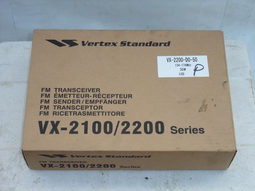 |
For both in-car and base/pit duty we use a pair of identical Vertex Standard VX-2200 VHF-FM radios from Rugged Radios in San Luis Obispo, California. We use Rugged Radios exclusively to supply our comms needs as they are helpful, competent, knowledgable, and great folks to deal with. They also provide critical on-site support to racers at the big events like the annual King of the Hammers race. You can check out the specs on the Vertex VX-2100/2200 series Spec Sheet and get full details from the Vertex VX-2200 Owner's Manual. The VX-2200 Series are full-featured FM transceivers designed for flexible mobile and base station business communications in the VHF Land Mobile band. |
||||||||||||||||||||||||||||||||||||||||||||||||||||||||||||||||||||||||||||||||||||||||
|
|||||||||||||||||||||||||||||||||||||||||||||||||||||||||||||||||||||||||||||||||||||||||
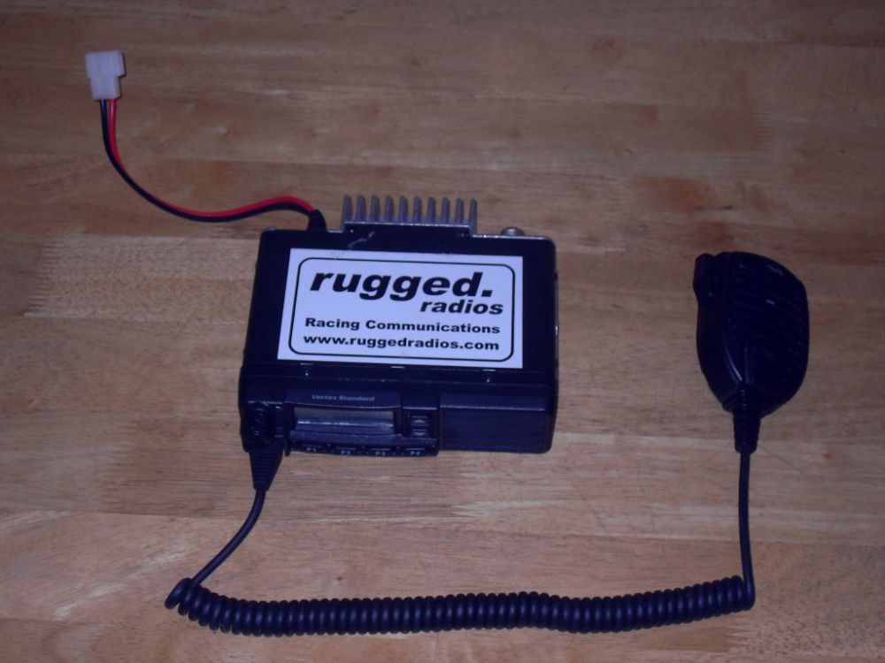 |
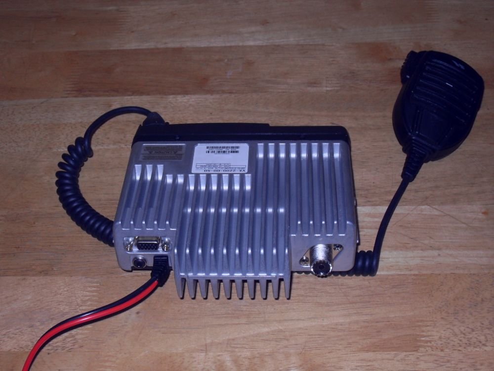
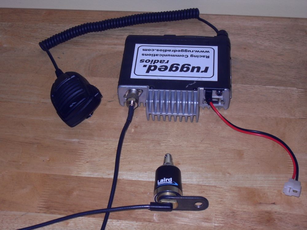
This is the bare radio with hand-held mic and power supply wires shown. We use the radio in this configuration for base/pit duty and also use it carried in a chase or pit vehicle. Later we'll look at how the other one is integrated into the racecar. Basic Specs are: Frequency Range 134 – 174 MHz |
||||||||||||||||||||||||||||||||||||||||||||||||||||||||||||||||||||||||||||||||||||||||
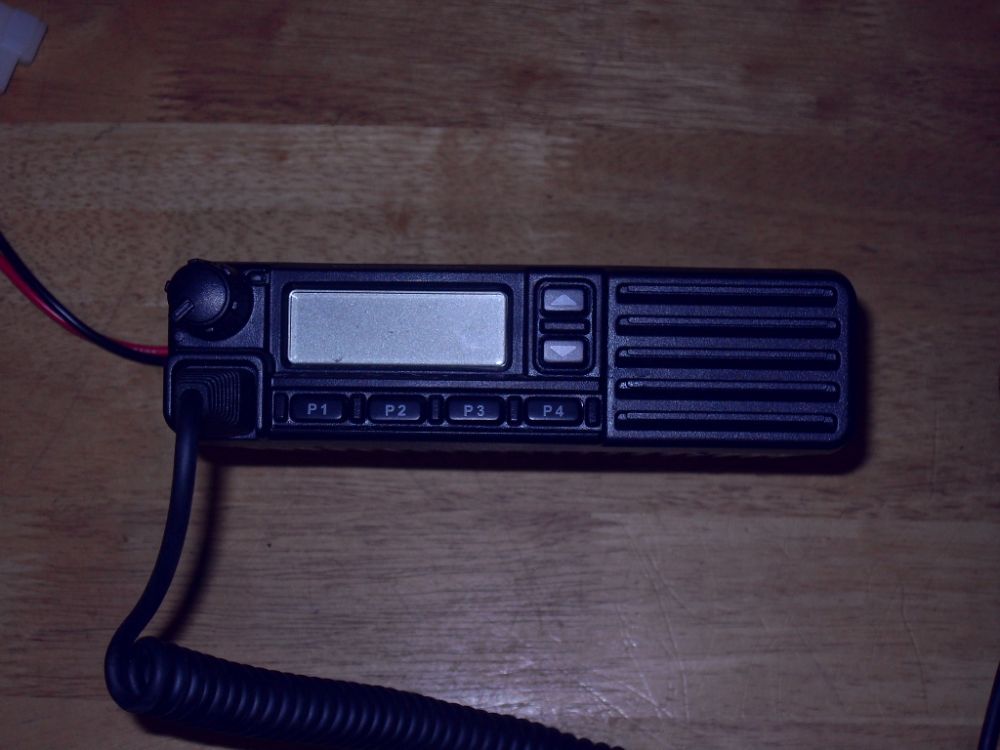 |
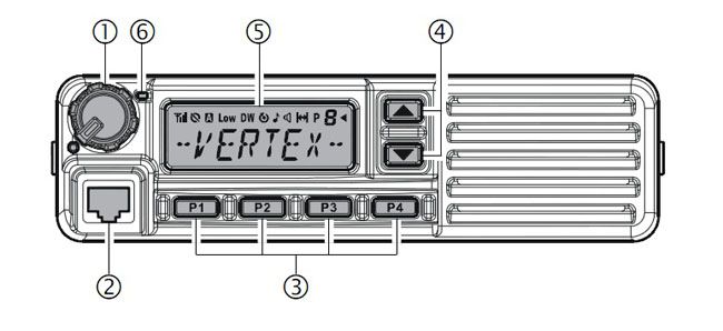
The front panel has very simple controls, easy to learn and easy to use with gloves on. There's an on/off/volume knob, LCD display, and 6 programmable function keys. The following diagram details the controls. |
||||||||||||||||||||||||||||||||||||||||||||||||||||||||||||||||||||||||||||||||||||||||
|
|||||||||||||||||||||||||||||||||||||||||||||||||||||||||||||||||||||||||||||||||||||||||
|
|||||||||||||||||||||||||||||||||||||||||||||||||||||||||||||||||||||||||||||||||||||||||
 |
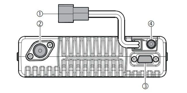
This is the back of the radio. The following diagram details the connections. |
||||||||||||||||||||||||||||||||||||||||||||||||||||||||||||||||||||||||||||||||||||||||
|
|||||||||||||||||||||||||||||||||||||||||||||||||||||||||||||||||||||||||||||||||||||||||
|
|||||||||||||||||||||||||||||||||||||||||||||||||||||||||||||||||||||||||||||||||||||||||
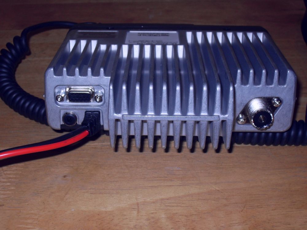 |
Close-up of the back panel. Note the extensive cooling fins moulded into the aluminum chassis. |
||||||||||||||||||||||||||||||||||||||||||||||||||||||||||||||||||||||||||||||||||||||||
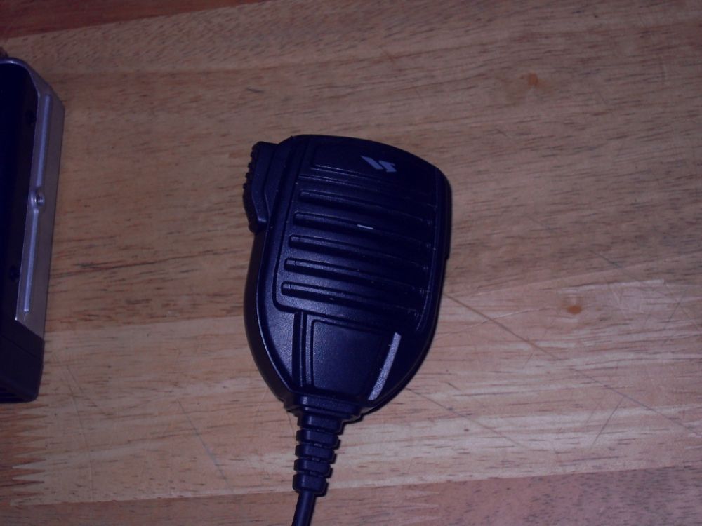 |
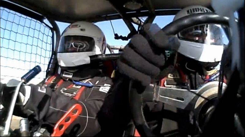
The supplied microphone is suitable for base station use, or when the radio is being used in a pit or chase vehicle, but would be difficult to use in a race vehicle while wearing a helmet. | ||||||||||||||||||||||||||||||||||||||||||||||||||||||||||||||||||||||||||||||||||||||||
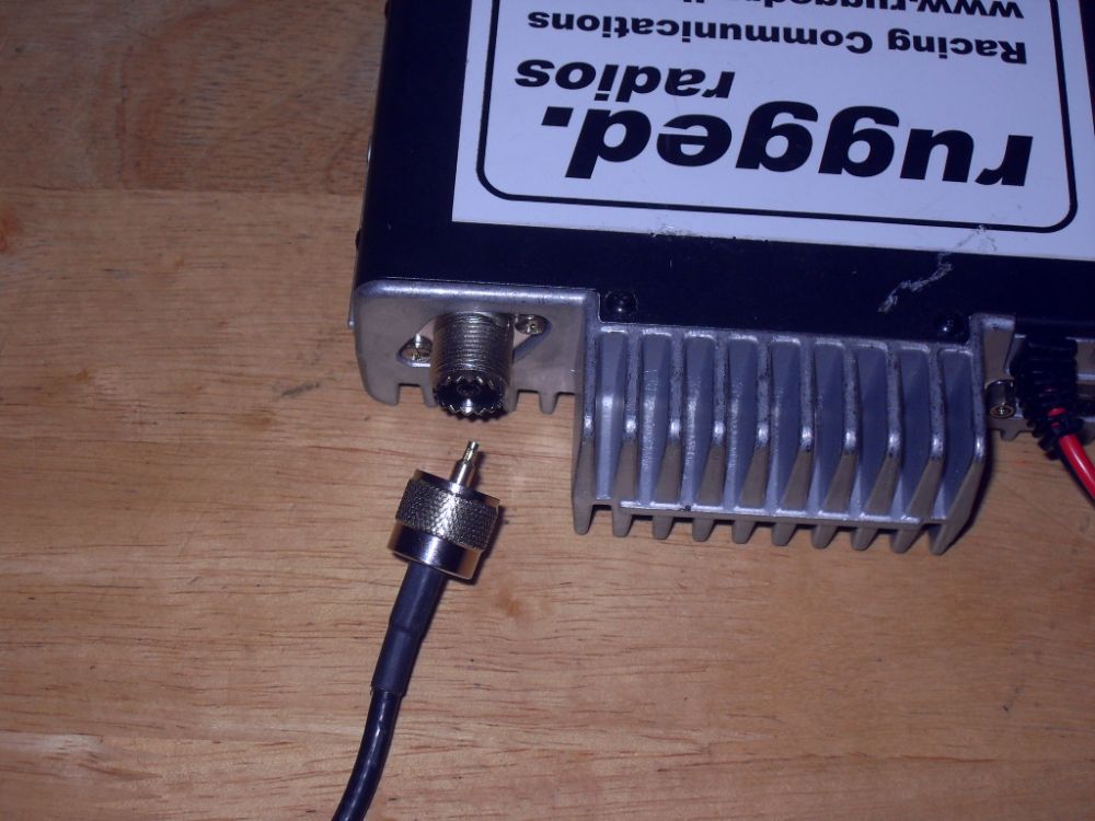 |
Type-M (PL-259) 50-Ohm coaxial antenna connection. | ||||||||||||||||||||||||||||||||||||||||||||||||||||||||||||||||||||||||||||||||||||||||
 |
Radio with antenna base connected (note that the "whip" of the antenna is not shown). | ||||||||||||||||||||||||||||||||||||||||||||||||||||||||||||||||||||||||||||||||||||||||
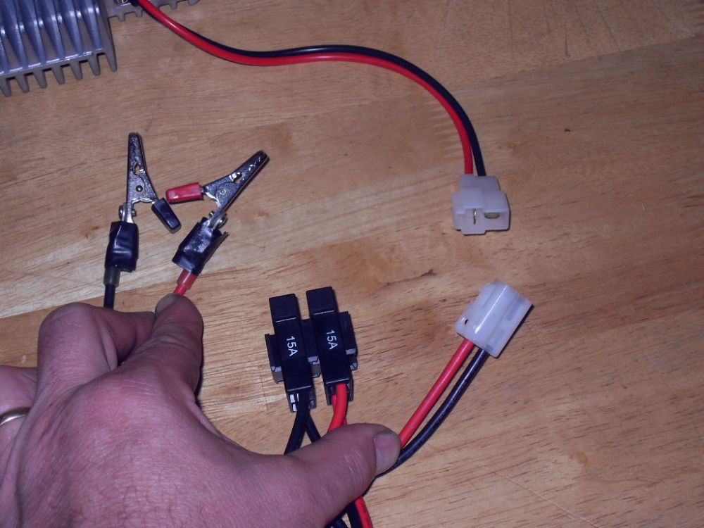 |
Because this radio is used both at camp/main pit and also in pit or chase vehicles, the power cables are modified with alligator clips for convenient connection to a variety of 12V+DC power sources (usually nothing more fancy than a spare automotive battery). | ||||||||||||||||||||||||||||||||||||||||||||||||||||||||||||||||||||||||||||||||||||||||
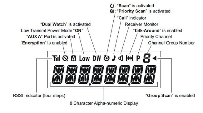
Radio OperationBecause of the huge number of features and possible programmable button combinations, I'm not going to detail every aspect of operating the radio, but will cover the basics. The following is a composite image of all possible indication that can be shown on the LCD display: |
|||||||||||||||||||||||||||||||||||||||||||||||||||||||||||||||||||||||||||||||||||||||||
 |
|||||||||||||||||||||||||||||||||||||||||||||||||||||||||||||||||||||||||||||||||||||||||
Channel ProgrammingAs discussed, radios of this type are preprogrammed by dealers like Rugged Radios so that certain specific frequencies are assigned channel numbers and then the user selects a channel for operation rather than setting an actual frequency. For some professional radio users, like military personnel, this can seem odd as they are used to using equipment where controls are used to set a specific frequency by selecting that actual frequency in kHz or MHz. But for most users, using channels is much more simple. |
|||||||||||||||||||||||||||||||||||||||||||||||||||||||||||||||||||||||||||||||||||||||||
 |
To make use even more simple, the Vertex VX-2200 has the capability to program each of the available 128-channels with an 8-character channel name so you don't have to memorize that, for example, Race Ops is channel 22. At left, the radio is tuned to Joint Force Racing's main operating channel, which is abbreviated JFR OPS. When you order a radio from Rugged Radios, you can submit to them a list of frequencies you would like programmed (within the frequency range of the radio model in question, of course) and the channel name. An obvious case would be when you want them to program a specific frequency for your team's use. |
||||||||||||||||||||||||||||||||||||||||||||||||||||||||||||||||||||||||||||||||||||||||
However, before Rugged ship you a radio, they also program it with a "standard" set of frequencies and channel names. For example, for Ultra4 / King of the Hammer's racing, commonly used frequencies include (in MHz): 151.490 - KOH Race Ops – Used internally to maintain control of the race. Also the main channel for the helo. 151.715 - KOH Relay – Used by the checkpoints to radio in their times. Also general channel monitored by Wild Bill (BFG Relay) 157.450 - KOH Medical – Used by ambulances, security, and recovery crews in resolution of emergency. Racers or fans would report emergencies on KOH Relay. 153.395 - BFG Pits – For racer to radio ahead to the BFG pits to let them know what they need. Other common frequencies in offroad racing include: 151.625 - Weatherman WARNING: DO NOT rely on the above listings to have your radio programmed, as they may be subject to change. Check with your race sanctioning body, race organizers, and your radio supplier for current frequencies applicable to your activity. Which brings me to an important point. I highly recommend buying your comms equipment from a respected dealer involved in the sport, like Rugged Radios, as Matt and the guys will be on site at the event, with their support equipment, able to help you with any last minute programming changes, spare parts, and other tech help. Here are some basic operations with the radio, using Rugged Radios standard function-key programming: |
|||||||||||||||||||||||||||||||||||||||||||||||||||||||||||||||||||||||||||||||||||||||||
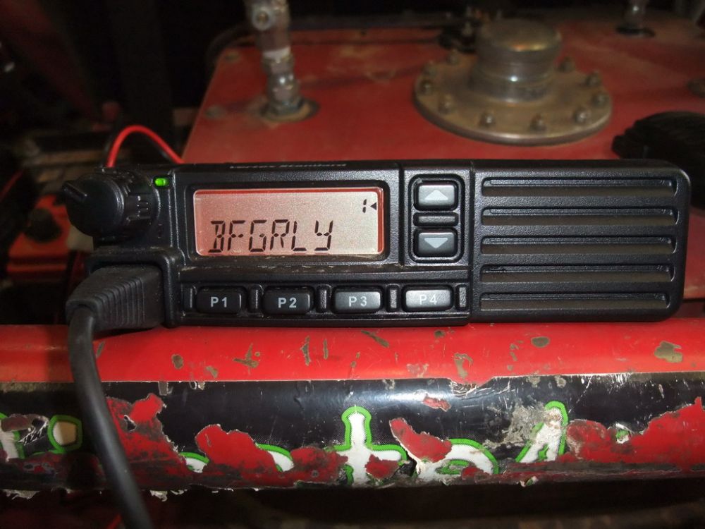 |
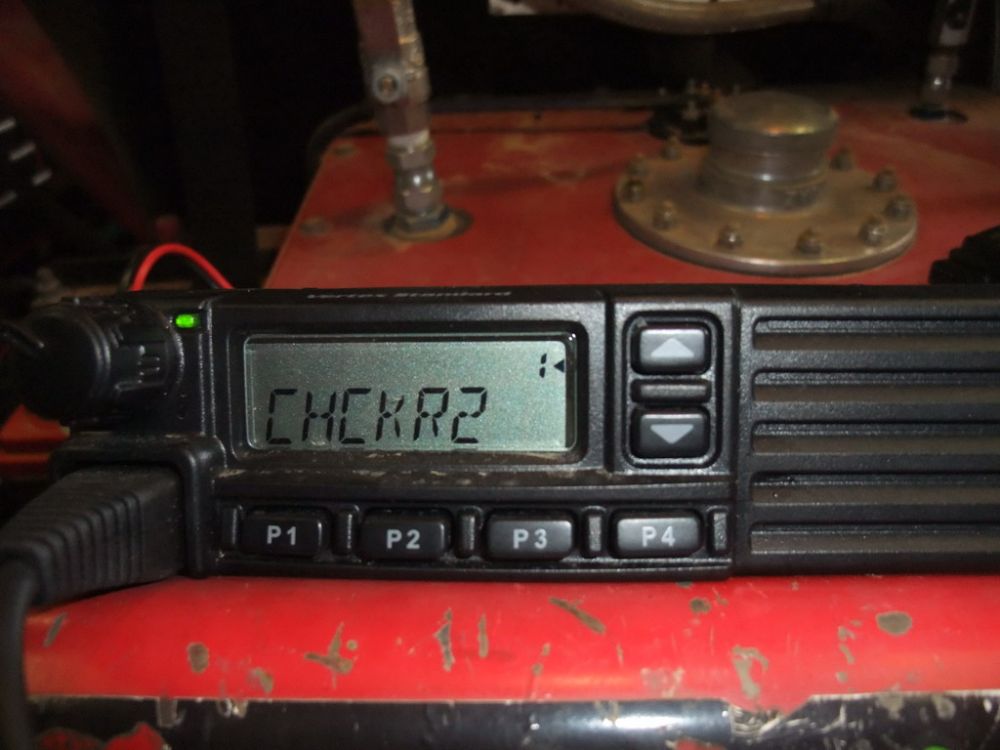
Powered on. The "1" indicates that the radio is on the first of the 8 groups of channels. This means that as the user cycles through the channels using the [▲]/[▼] keys, they will scroll through those channels assigned to group 1. This system of grouping channels alleviates the need to scroll through 50 plus channels to get to the one you want. The ◄ beside the "1" indicates that Group Scan feature is enabled. The Scanning feature is used to monitor multiple channels programmed into the transceiver. While scanning, the transceiver will check each channel of the programmed group for the presence of a signal, and will stop on a channel if a signal is present. The alpha-numeric display indicates that the radio is currently set to the BFG Relay frequency. |
||||||||||||||||||||||||||||||||||||||||||||||||||||||||||||||||||||||||||||||||||||||||
 |
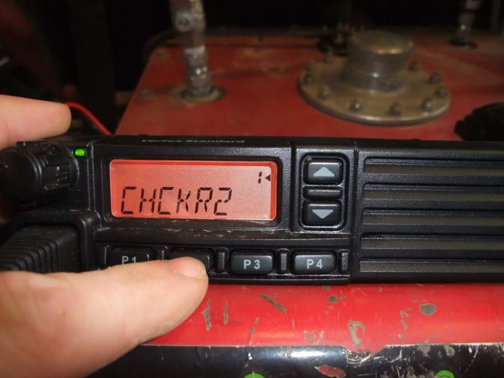
To cycle through the channels in Group 1, repeatedly press the [▲] or [▼] keys. Here we are on BFG Pit channel... |
||||||||||||||||||||||||||||||||||||||||||||||||||||||||||||||||||||||||||||||||||||||||
|
... and now Joint Force Racing Ops. If you press and hold one of the [▲] or [▼] keys, the radio to begin stepping repeatedly upward or downward through the programmed channels until you release it. |
||||||||||||||||||||||||||||||||||||||||||||||||||||||||||||||||||||||||||||||||||||||||
 |
SquelchPress [P1] and you are able to adjust the squelch level. SQLLV and the current level (from 1 to 10) is displayed. Use the [▲] or [▼] keys to adjust the squelch to the desired level. Press [P1] again to exit. Press and hold [P1] to turn squelch OFF. You will hear static on the radio and the TX/BUSY indicator light blinks green. |
||||||||||||||||||||||||||||||||||||||||||||||||||||||||||||||||||||||||||||||||||||||||
 |
BacklightThe [P2] key is programmed as the backlight adjustment key (dimmer switch). Here, the backlight is off... |
||||||||||||||||||||||||||||||||||||||||||||||||||||||||||||||||||||||||||||||||||||||||
 |
...and here it is on. Pressing [P2] repeatedly cycles through the four available backlight settings, OFF/1/2/3. Use P2 to select the brightness level of the display. | ||||||||||||||||||||||||||||||||||||||||||||||||||||||||||||||||||||||||||||||||||||||||
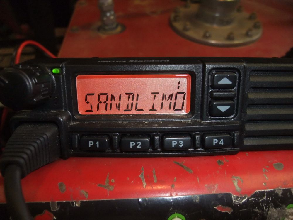 |
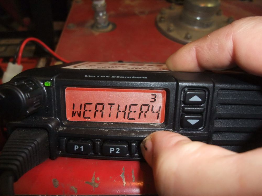
Channel Group SelectionMy radio came from Rugged with their standard set of channels plus a unique channel for Joint Force Racing Ops all programmed and divided into three channel groups. Here the radio is tuned to the "Sand Limo" channel, which is in group 1. (Don't ask me what "Sand Limo" is - sounds like some kind of So-Cal Pismo beach sand-rail thing - I haven't a clue! ;-) |
||||||||||||||||||||||||||||||||||||||||||||||||||||||||||||||||||||||||||||||||||||||||
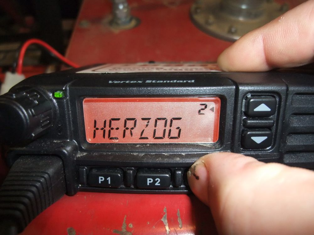 |
To tune to a channel that is in group 3, press the [P3] key once to switch to group 2, then cycle through the channels in Group 2 by repeatedly pressing the [▲] or [▼] keys until you arrive at the desired channel on the display. | ||||||||||||||||||||||||||||||||||||||||||||||||||||||||||||||||||||||||||||||||||||||||
 |
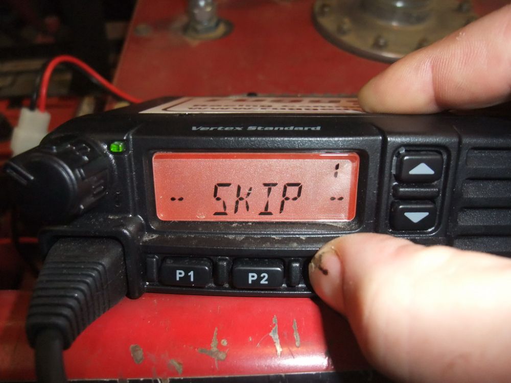
Press [P3] again and we get group 3. Once the desired channel is selected, any transmissions made on that channel within range will automatically be heard, and if we either key the handheld microphone or depress a connected PTT switch, when we speak our transmission will be broadcast on this channel. |
||||||||||||||||||||||||||||||||||||||||||||||||||||||||||||||||||||||||||||||||||||||||
 |
Advanced FeaturesThat's the basics of Vertex VX-2200 operation. There are a good many other advanced capabilities the radio has, which may or may not be programmed by your dealer to map to the keys, such as: Channel Scan, Group Scan, Dual-Watch, Talk Around, Follow-me, Lone Worker, and Public Address. Consult your dealer / programmer and/or consult the Vertex VX-2200 Owner's Manual for details. |
||||||||||||||||||||||||||||||||||||||||||||||||||||||||||||||||||||||||||||||||||||||||
Speaking of PTT switches, we have so far covered the basics of radio operation showing JFR's pit radio. I promised to detail how to integrate a radio into the race car and build a complete comms system for the car, so we'll do that now.
Additional ComponentsFirst, we need a few more things besides the actual radio, namely:
Helmets |
|||||||||||||||||||||||||||||||||||||||||||||||||||||||||||||||||||||||||||||||||||||||||
 |
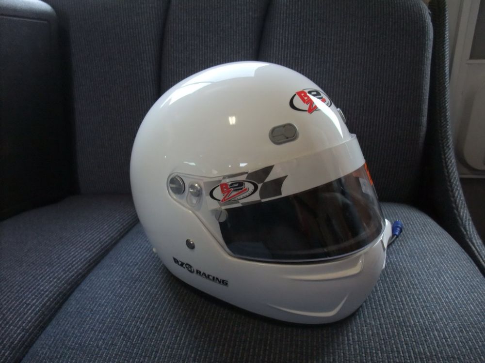
You can't use a normal hand-held microphone at speed or with a helmet on, so the driver and codriver will need helmets with integrated speakers to hear the radio and an integrated microphone so they can transmit. JFR uses the Zamp RZ-51 Air which has an integrated air intake for the race car's fresh air supply, and is modified by Rugged Radios with speakers and microphone. |
||||||||||||||||||||||||||||||||||||||||||||||||||||||||||||||||||||||||||||||||||||||||
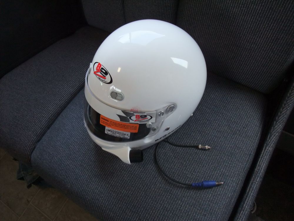 |
Such a helmet is often called "wired and blown", meaning it has provisions for comms as well as fresh air. You can see the air intake on the left chin guard are here, as well as the comms wiring. The larger male plug fits into the vehicle headset cords. The smaller plug can be connected to a standard mini 3.5mm stereo plug such as that on a portable music player (iPod, MP3 player, etc.) or mobile phone. |
||||||||||||||||||||||||||||||||||||||||||||||||||||||||||||||||||||||||||||||||||||||||
 |
Basic features of the helmet are:
|
||||||||||||||||||||||||||||||||||||||||||||||||||||||||||||||||||||||||||||||||||||||||
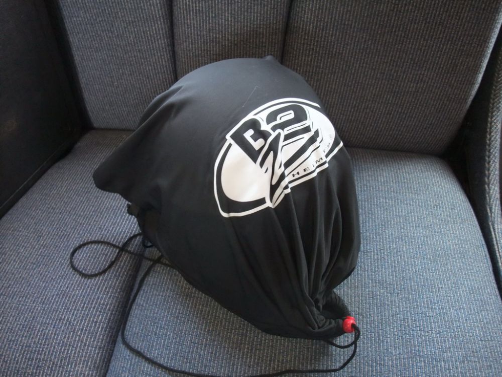 |
It comes with a nice soft bag for carrying and storage. Proper storage is important to avoid damage to your helmet. Avoid contact with extreme heat or cold. Do not use any solvents or chemicals to clean your helmet. For cleaning, use a mild soapy water and wipe dry with a clean cloth. Allow helmet to fully dry prior to storage. |
||||||||||||||||||||||||||||||||||||||||||||||||||||||||||||||||||||||||||||||||||||||||
 |
Air Intake and helmet wiring. Of course, the helmet's most important job is to protect the wearer's head from injury, and it can only do that if it properly sized. It's said that somewhere between 50% and 80% of helmet wearer's are wearing a helmet that is improperly sized (usually too big). |
||||||||||||||||||||||||||||||||||||||||||||||||||||||||||||||||||||||||||||||||||||||||
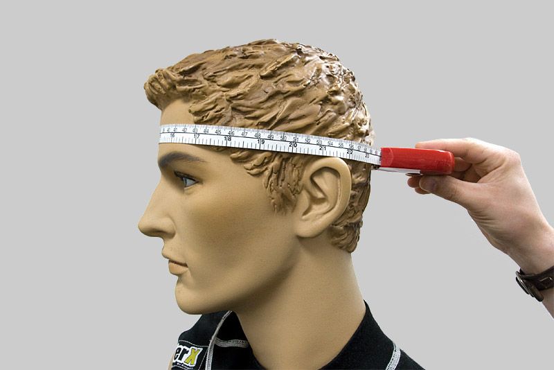 |
To determine your helmet size simply measure the circumference of your head above your ears and around your forehead as illustrated. Take the measurement around the circumference of your head at the widest point. This normally occurs at a point approximately one inch above the eyebrows in front, just above the ears, and around the point on the back of your head that will give you the largest measurement. Use a flexible tape and take several measurements, to make sure you have the largest one. |
||||||||||||||||||||||||||||||||||||||||||||||||||||||||||||||||||||||||||||||||||||||||
With this measurement in hand, consult the manufacturer's sizing chart. Zamp's chart is as follows:
The sizing chart is a good place to start, but for maximum comfort and protection, a helmet should always be tried on. Helmets should fit down on top of the head so there is no gap between the helmet and the person's head. The front of the helmet should lay just above the eyebrows for a proper fit. The helmet should not pivot on top of the head, that would mean it's too small. The front of the helmet should not come down over the eyebrows, that would mean the helmet is too large. The chinstrap should fit snug under the chin. If it is too tight it will cause discomfort and possible choking. If it is too loose it could cause the helmet to slip during a crash and defeat its protection. |
|||||||||||||||||||||||||||||||||||||||||||||||||||||||||||||||||||||||||||||||||||||||||
 |
For maximum protection, the helmet must fit snugly. To ensure proper fit, put helmet on head and move side to side - your skin on your forehead and cheeks should move the same amount as the helmet. |
||||||||||||||||||||||||||||||||||||||||||||||||||||||||||||||||||||||||||||||||||||||||
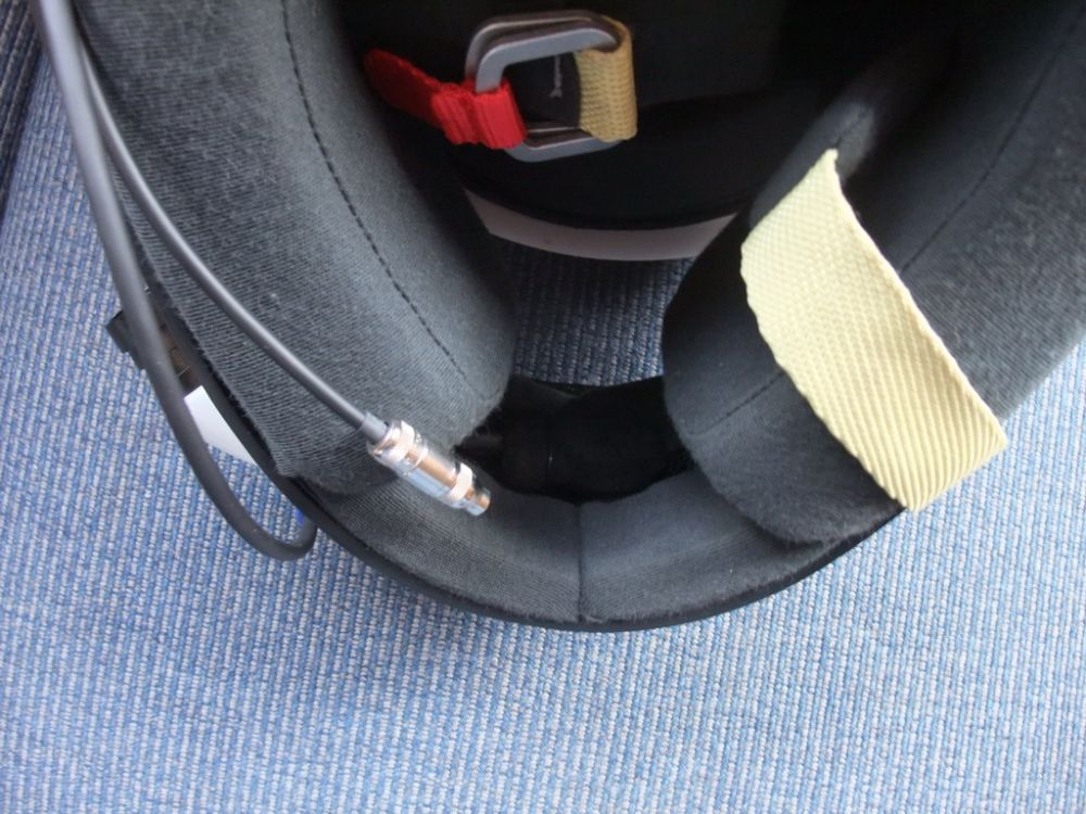 |
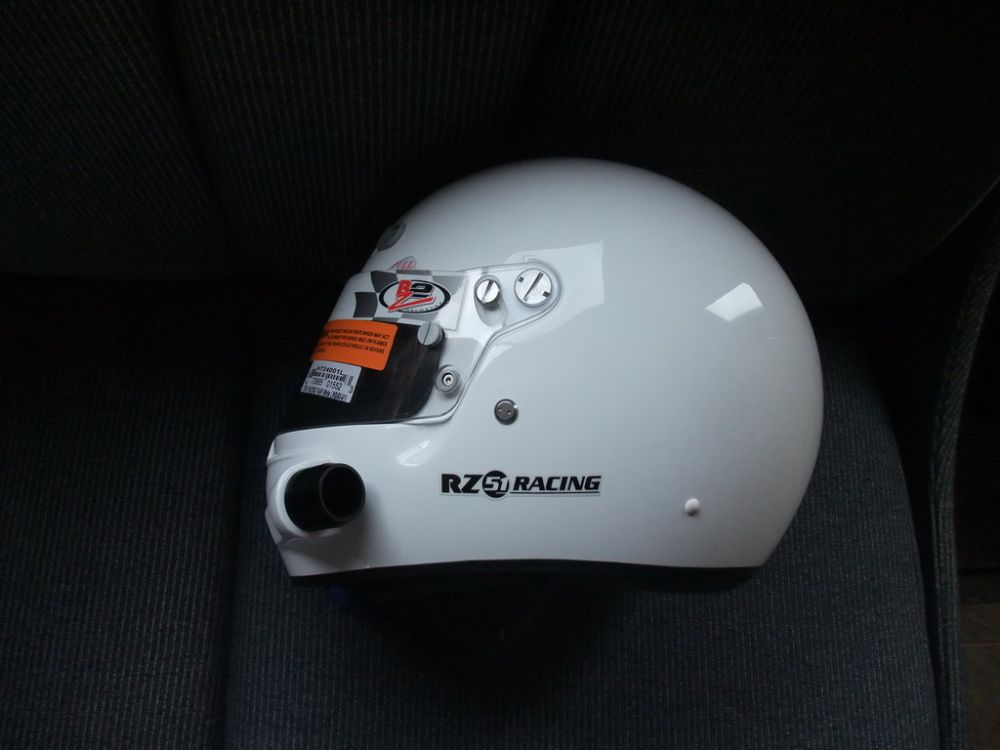
In this shot we can see the microphone nestled just inside the chin guard. Depending on the helmets fit, it can be a little obtrusive fitted here. The combination of helmet size I use and the shape of my head left the microphone closer to my face/lips that I liked. In an accident, the helmet will move on the head somewhat and if the microphone is too close, it can cause additional injury to the mouth / teeth. Rugged Radios did a great job wiring the helmet, and it's a very nice helmet that I find very comfortable and practical, but I feel they could have done a better job integrating the microphone by recessing it further into the chin guard. |
||||||||||||||||||||||||||||||||||||||||||||||||||||||||||||||||||||||||||||||||||||||||
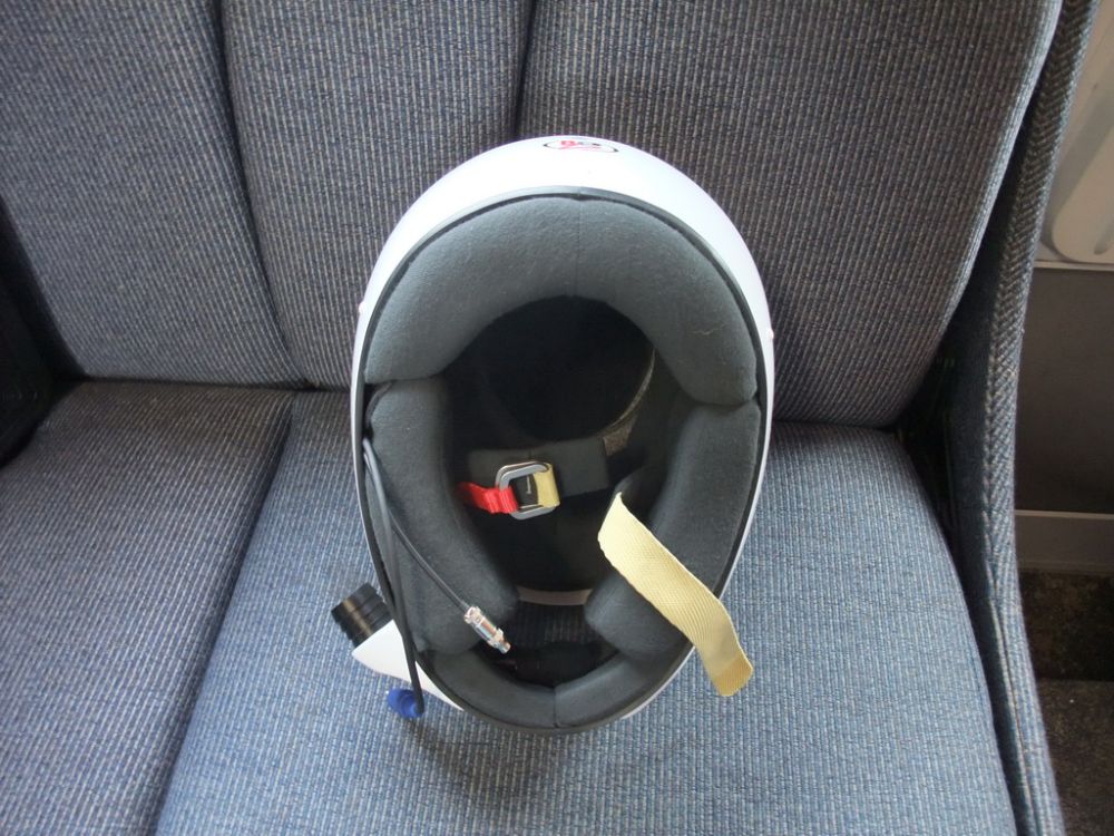 |
Underside of helmet, showing double D-ring attachment style. |
||||||||||||||||||||||||||||||||||||||||||||||||||||||||||||||||||||||||||||||||||||||||
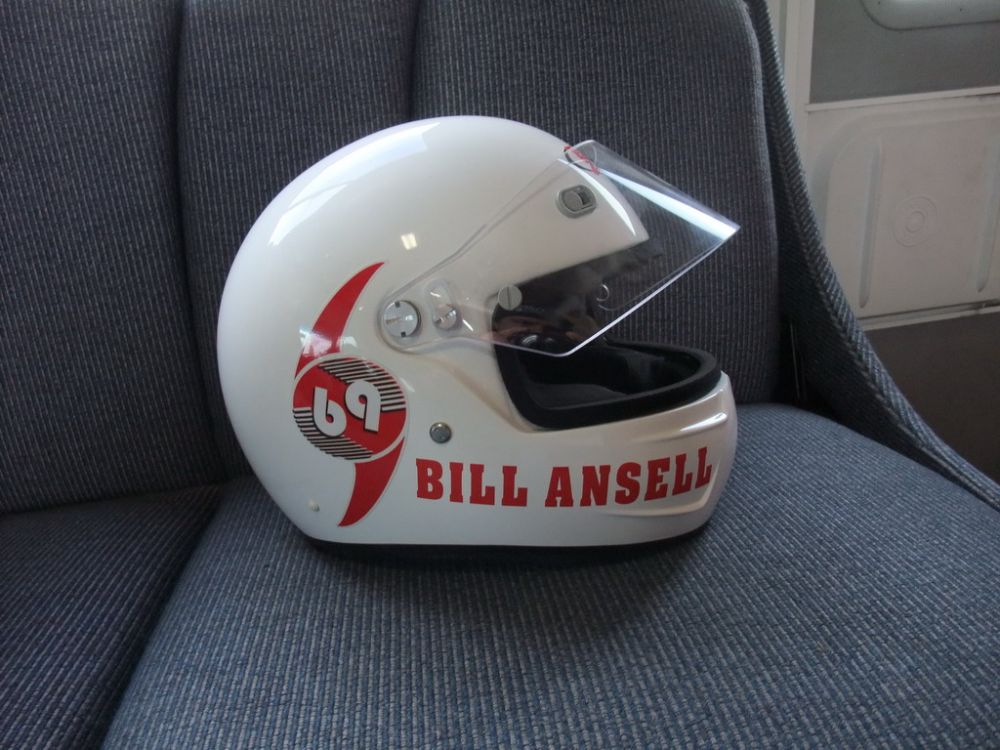 |
Of course, the MOST important thing is to jazz up your helmet with snazzy custom graphics! ;-) These awesome Joint Force Racing stickers from Big Horn Graphics really make the helmet! |
||||||||||||||||||||||||||||||||||||||||||||||||||||||||||||||||||||||||||||||||||||||||
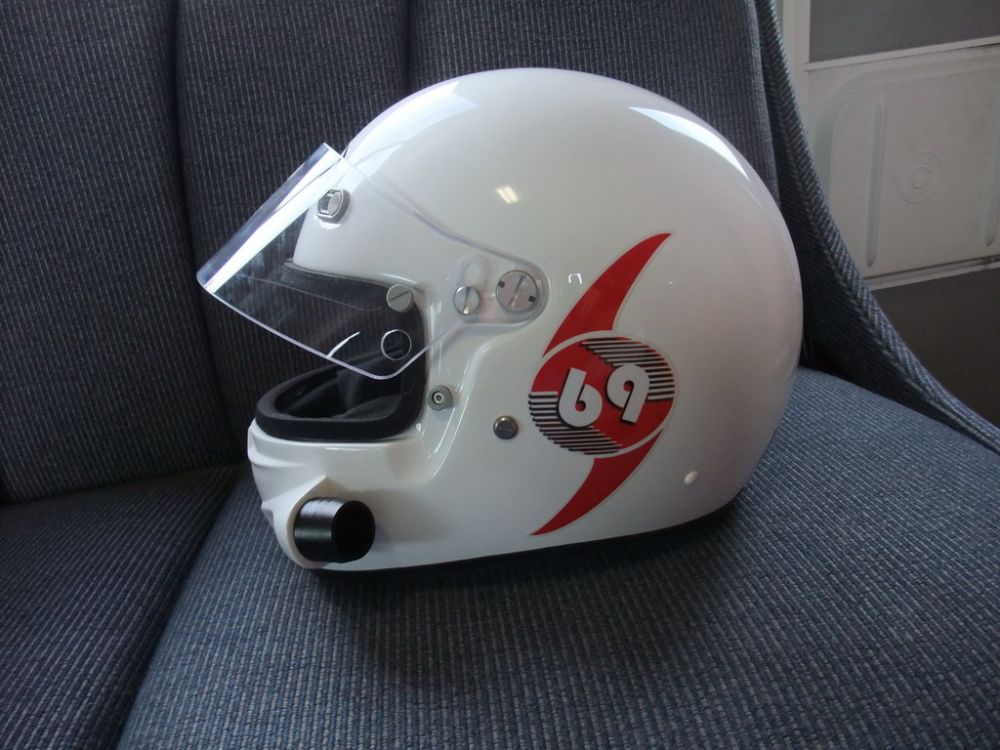 |
Operating a motor vehicle or participating in racing and other extreme sports is dangerous. No helmet can protect the user against all foreseeable impacts. For maximum protection, this helmet must fit firmly and chin strap be fastened securely at all times. This helmet has been constructed so that the energy of a severe blow is absorbed by the helmet, causing the shell and/or liner to be partially destroyed. Although the damage may not be visible to the user, if the helmet does experience a severe blow, return it to the manufacturer for inspection or destroy and replace the helmet. Of course, with these badass Car69 stickers, this one's a collector's item! |
||||||||||||||||||||||||||||||||||||||||||||||||||||||||||||||||||||||||||||||||||||||||
AntennaThe antenna is a small but very important part of the system. You will get noticeably better results and more range with your radios with a quality antenna, especially if you place it as high as possible. It is the single most important factor in increasing transmitting and receiving range of a radio. You'll need to make sure you choose an antenna that is specifically designed for the frequencies and application you are using and then choose the best location possible to install it. Antenna theory is a really complicated subject, and requires a detailed knowledge of wave theory going WAY beyond what we have covered here. |
|||||||||||||||||||||||||||||||||||||||||||||||||||||||||||||||||||||||||||||||||||||||||
 |
That's why we just use the antenna that Rugged recommend for use with our Vertex radios. They are available in both tab-mount (shown here), which we installed on the race car, as well as magnetic mount which we use when we take our second radio on the road in a pit or chase vehicle. |
||||||||||||||||||||||||||||||||||||||||||||||||||||||||||||||||||||||||||||||||||||||||
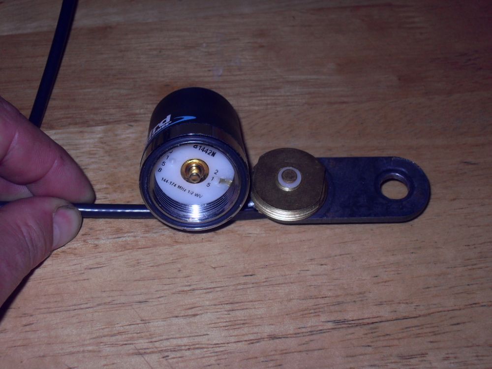 |
That said, here's a neat tip that shows that there is some practical use to all the theory that we covered at the beginning of this article. The length of an antenna has to be matched to the wavelength of the frequency that it transmits. If you look closely at this pic, you will see that the antenna base is marked "144-174 MHz 1/2WV" This means it is intended to transmit in that frequency band using a half-wavelength. So? |
||||||||||||||||||||||||||||||||||||||||||||||||||||||||||||||||||||||||||||||||||||||||
Well, if you ever roll over and break or loose the antenna whip and find that you need to fashion an emergency replacement at the next pit stop - this tells you how long it needs to be. Recalling the relationship between frequency and wavelength and the rule of thumb, we can calculate that the wavelength, and therefore the length of the antenna whip, since it will be half this (for a half-wave antenna like this) We simply divide the speed of light in metres per second by the frequency in Hz to get the wavelength in metres. So, at the upper end of the range we get:
For those who can't do math in their heads (I'm talking to you Bigelow!), an easier way is to divide 300 by your freq. in MHz, so if your team freq is 150MHz, then 300 / 150 = 2. Wavelength = 2m, therefore 1/2 wave antenna should be about 1m or roughly 3 feet in length! |
|||||||||||||||||||||||||||||||||||||||||||||||||||||||||||||||||||||||||||||||||||||||||
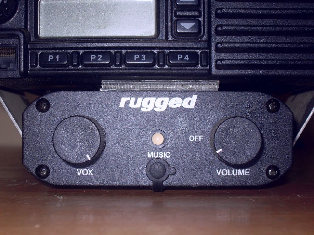 |
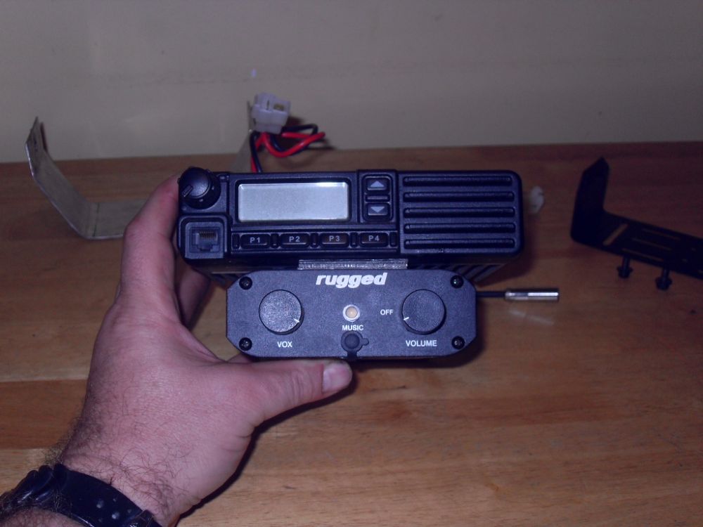
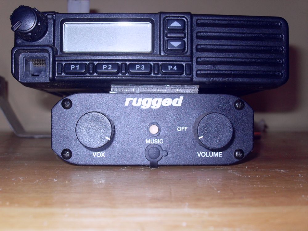
IntercomThe heart of the racecar's comms system is the intercom unit. It ties everything else together and provides centralized integrated control as well as driver-to-codriver in-car communications. This unit is the RRP600 from Rugged Radios and it's a fantastic little unit. In fact, once you've used one in a race car you'll want one in your trail rig as well - it's just that cool. The controls are super simple, and easy to manipulate with gloved hands. On the right is the rotary on/off/volume control that functions as a master volume and controls the volume of the radio, the intercom itself, and any music device you attach to the small centralized input port. On the left is the VOX sensitivity adjustment. VOX stands for voice-activated transmit. For intercom comms between driver and codriver, instead of having to press a PTT switch, the helmet mics become voice-activated.
|
||||||||||||||||||||||||||||||||||||||||||||||||||||||||||||||||||||||||||||||||||||||||
| I`ve used many VOX systems before, both military and civilian, and often the performance is less than optimal - either so sensitive that, activated by ambient noise (like wind), it continually cuts in and out when you don't want it to. Or, it's so insensitive that, every time you speak, the first word or two are always clipped or garbled. The idea of VOX is very appealing but a poorly performing VOX system is a hateful thing to use. | |||||||||||||||||||||||||||||||||||||||||||||||||||||||||||||||||||||||||||||||||||||||||
 |
The performance of the Rugged RRP600 is, however, excellent! The VOX is easy to adjust to the perfect sensitivity, depending on conditions (we have to set ours to fairly low sensitivity because of all the noise because we're just that damn fast!), and the response is fast and precise. It makes communications between driver and codriver effortless. In turn, this reduces stress and increases effectiveness - no more "What?" or "I thought you said left?". This is particularly important when you're as fast as JFR! Honestly, I can't say enough good things about the unit - it's that good. Also check out the Rugged Radios RRP600 Instruction Manual. |
||||||||||||||||||||||||||||||||||||||||||||||||||||||||||||||||||||||||||||||||||||||||
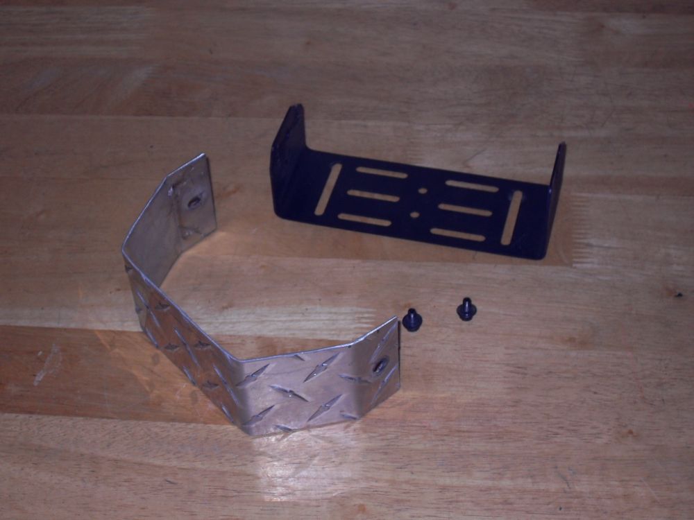 |
Mounting BracketsThe Vertex radio comes with a decent mounting bracket, and we simply added a custom-bent scrap of aluminum diamond-plate to create an integrated mount for radio and intercom, as seen above. I think Charlie had the diamond-plate kicking around the shop left over from his old mid-90's Top Truck Challenge truck! |
||||||||||||||||||||||||||||||||||||||||||||||||||||||||||||||||||||||||||||||||||||||||
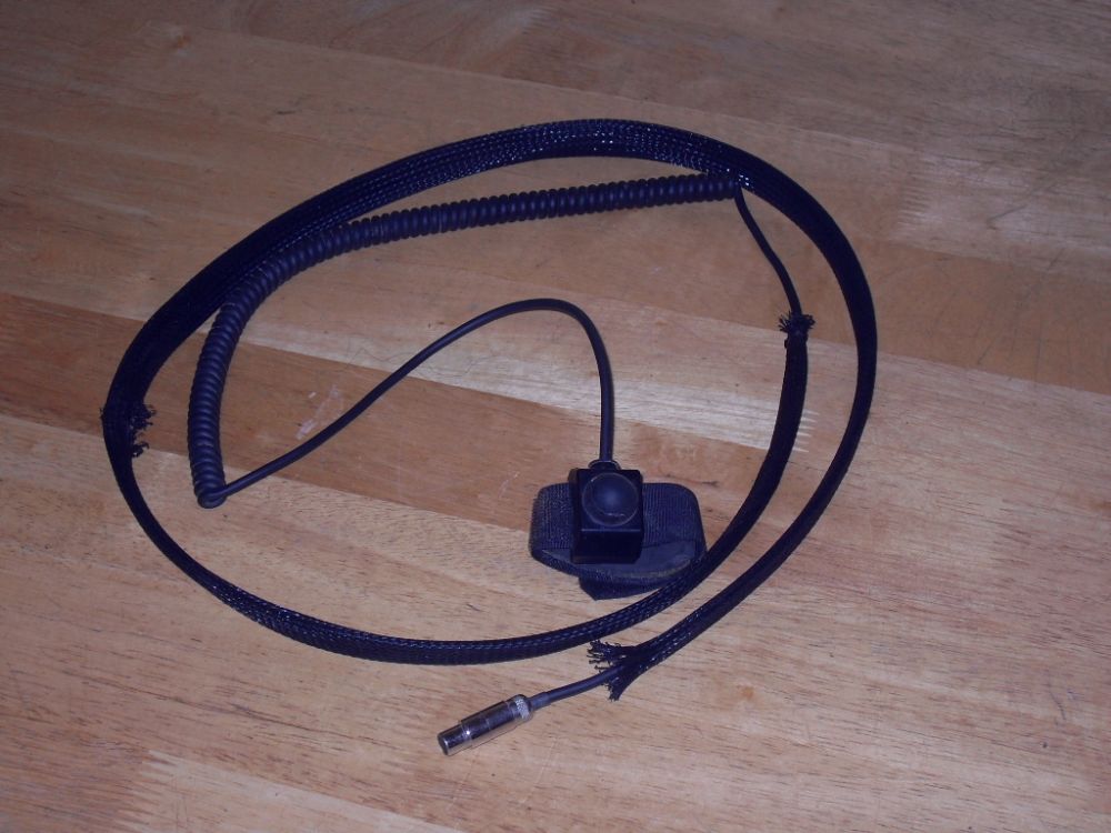 |
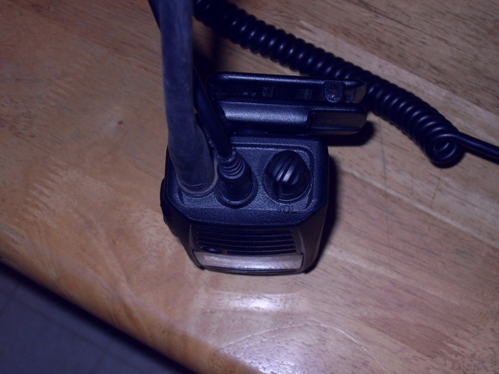
PTT SwitchesThis is a Rugged Radios PTT switch for use with the Vertex radio. You don't normally want to use VOX with an external radio, as any inadvertent activation would be transmitted, which is annoying to other units on the net. As mentioned, it's also impossible to use a traditional CB-style mic while wearing a helmet. These PTT switches are therefore the ideal solution. They plug into the intercom unit and offer a nice long cord with a curly-cord end for mounting location flexibility. Once installed, they take the place of the microphone switch, and when depressed allow transmission on the selected radio frequency. The button itself can be located anywhere the user finds convenient, such as on a control or handle, or clipped to a harness or clothing. If a user needs to be able to transmit while both hands are otherwise occupied, a foot switch or pedal PTT could be used. |
||||||||||||||||||||||||||||||||||||||||||||||||||||||||||||||||||||||||||||||||||||||||
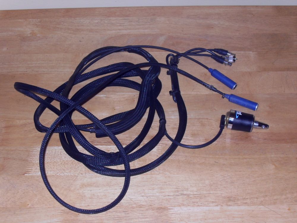 |
Helmet Headset CordsThe final piece needs for a complete in-car setup is a pair of helmet headset cords, shown here with the antenna base. These also plug into the intercom and provide a pair of stereo two-way headset jacks, one for driver and one for codriver, into which they plug their helmets. This connects the helmet's speakers and microphone to the intercom, and through the intercom to the radio as well. Now, with a wired helmet, headset cord, PTT, intercom, radio, and antenna, you are set up for complete in-car and external communications. We'll cover how to wire it all together shortly. There's just one last thing to consider as part of the complete comms package |
||||||||||||||||||||||||||||||||||||||||||||||||||||||||||||||||||||||||||||||||||||||||
 |
Hand-held RadioI consider a hand-held radio that transmits and receives on the same frequency as the race-car radio an essential part of the team's comms system.
|
||||||||||||||||||||||||||||||||||||||||||||||||||||||||||||||||||||||||||||||||||||||||
 |
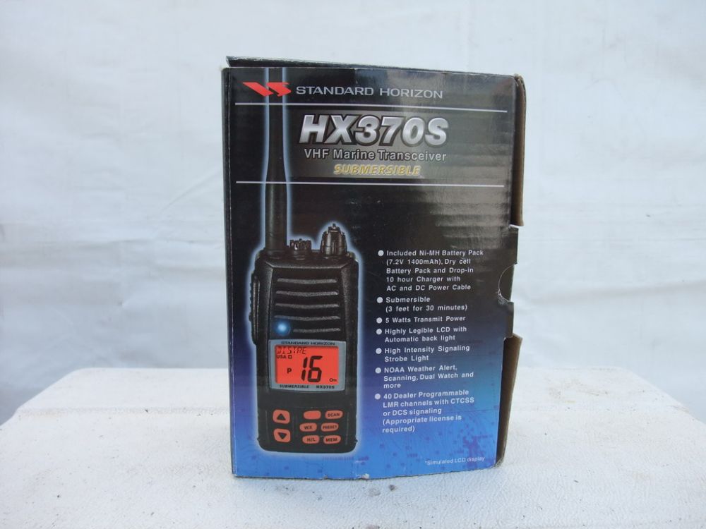
This is the Standard Horizon HX370S VHF/FM Handheld Transceiver from Rugged Radios. The HX370S is a submersible, miniature 5-Watt portable two-way VHF marine transceiver. It operates in the following frequency range: 156.025 to 157.425 MHz (Marine Band) |
||||||||||||||||||||||||||||||||||||||||||||||||||||||||||||||||||||||||||||||||||||||||
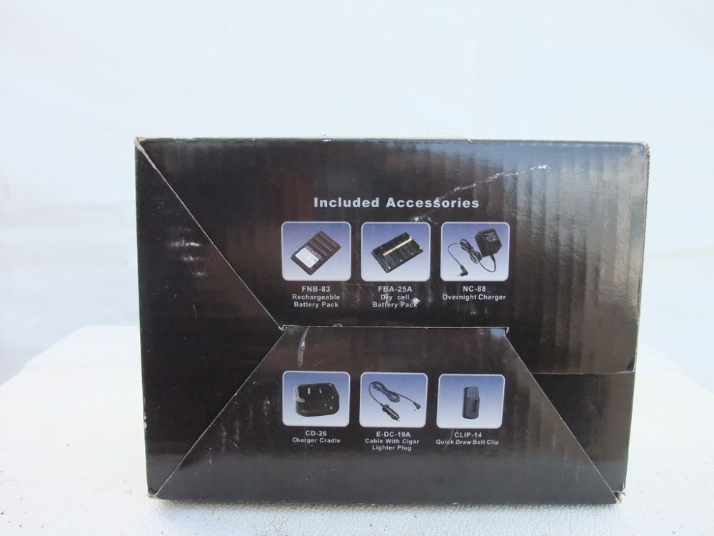 |
Like the Vertex mobile radios, channels are programmed by your dealer. The HX370S is capable of programming 40 LMR (Land Mobile Radio) Rugged Radios set us up with mobile and handheld radios all programmed alike. The radio comes with a bunch of handy accessories, as shown in this pic. |
||||||||||||||||||||||||||||||||||||||||||||||||||||||||||||||||||||||||||||||||||||||||
 |
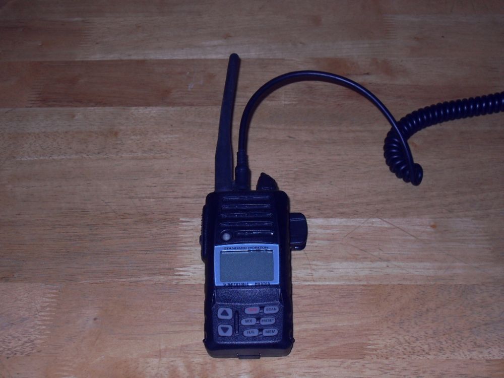
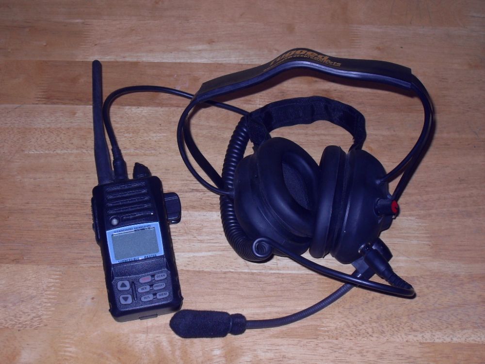
When used with a headset like the Rugged Radios H41, pictured here, the handheld is an invaluable tool for the crew chief. Not only does it allow him to communicate effectively with the car occupants, but it really enhances safety. No more yelling or hand-waving, simple, professional radio comms keep things cool and under control when you're in the pits. |
||||||||||||||||||||||||||||||||||||||||||||||||||||||||||||||||||||||||||||||||||||||||
 |
The HX370S includes the following features:
The transmitter provides a maximum of 5 Watts output, and has the selection of 2.5 Watts and 1 Watt to assist the user in ensuring maximum battery life. For more details, check out the HX370S Owner's manual. |
||||||||||||||||||||||||||||||||||||||||||||||||||||||||||||||||||||||||||||||||||||||||
 |
This is Ricky's complete crew-chief setup. | ||||||||||||||||||||||||||||||||||||||||||||||||||||||||||||||||||||||||||||||||||||||||
 |
Here Ricky's using the handheld to communicate with Charlie as we do some suspension testing at the 2010 King of the Hammers using Doug Bigelow's rig as a ramp! | ||||||||||||||||||||||||||||||||||||||||||||||||||||||||||||||||||||||||||||||||||||||||
Wiring & Installation |
|||||||||||||||||||||||||||||||||||||||||||||||||||||||||||||||||||||||||||||||||||||||||
 |
Here's the radio and intercom together. Note the compact size (I do not have giant hands!) | ||||||||||||||||||||||||||||||||||||||||||||||||||||||||||||||||||||||||||||||||||||||||
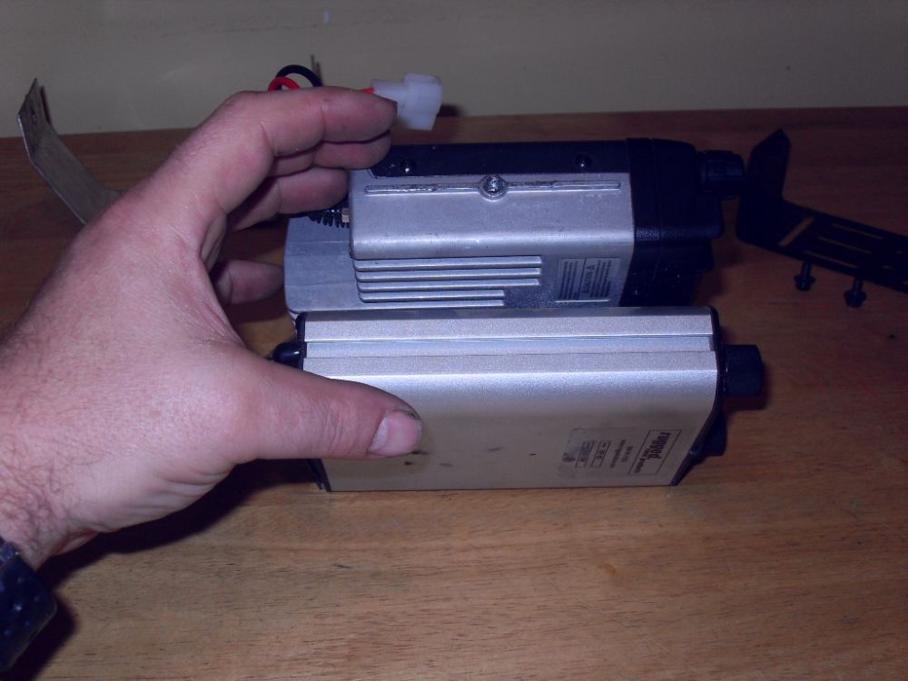 |
Side view. | ||||||||||||||||||||||||||||||||||||||||||||||||||||||||||||||||||||||||||||||||||||||||
 |
We stuck the two together using some heavy duty industrial hook-and-loop fastener which you can see between them in this pic. | ||||||||||||||||||||||||||||||||||||||||||||||||||||||||||||||||||||||||||||||||||||||||
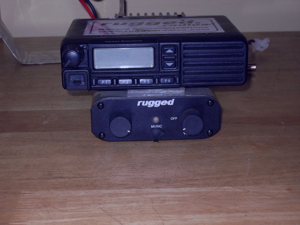 |
It makes sense to mount them together since they both need to be mounted away from sources of EM interference (ignition boxes, etc.) and ideally both within easy reach of both driver and codriver. | ||||||||||||||||||||||||||||||||||||||||||||||||||||||||||||||||||||||||||||||||||||||||
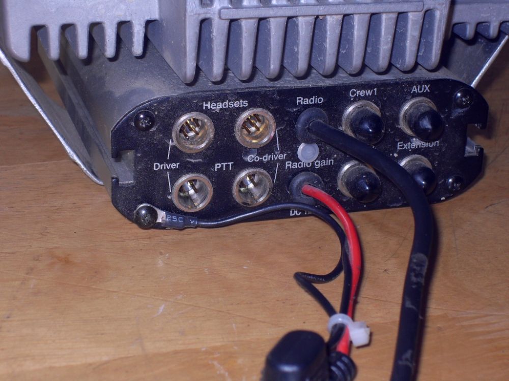 |
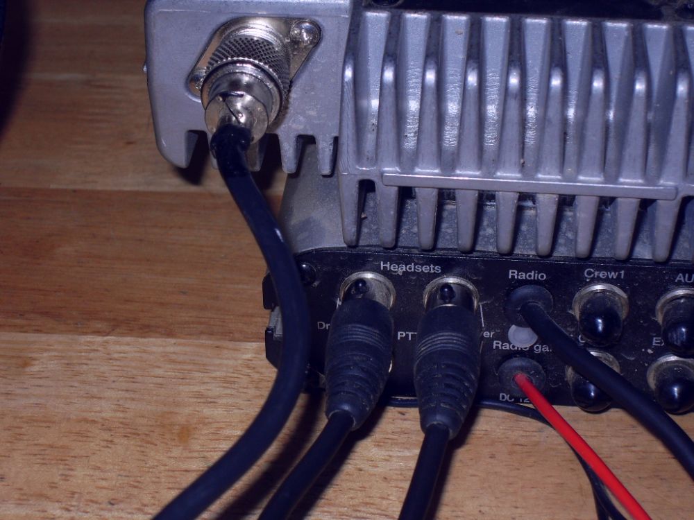
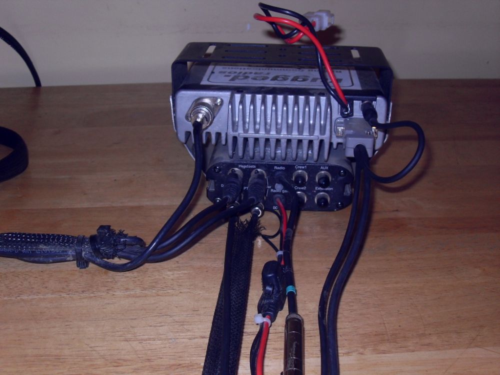
This is the back of the intercom unit, showing the connections. From left to right: Driver headset cord (top) and PTT connection (bottom) Codriver headset cord and PTT connection Radio wire - integrates the radio with the intercom. Power and Ground for intercom. The remaining four connections (with rubber caps) are not used in our setup, but can be used to extend the intercom's functionality as described in the Rugged Radios RRP600 Instruction Manual. |
||||||||||||||||||||||||||||||||||||||||||||||||||||||||||||||||||||||||||||||||||||||||
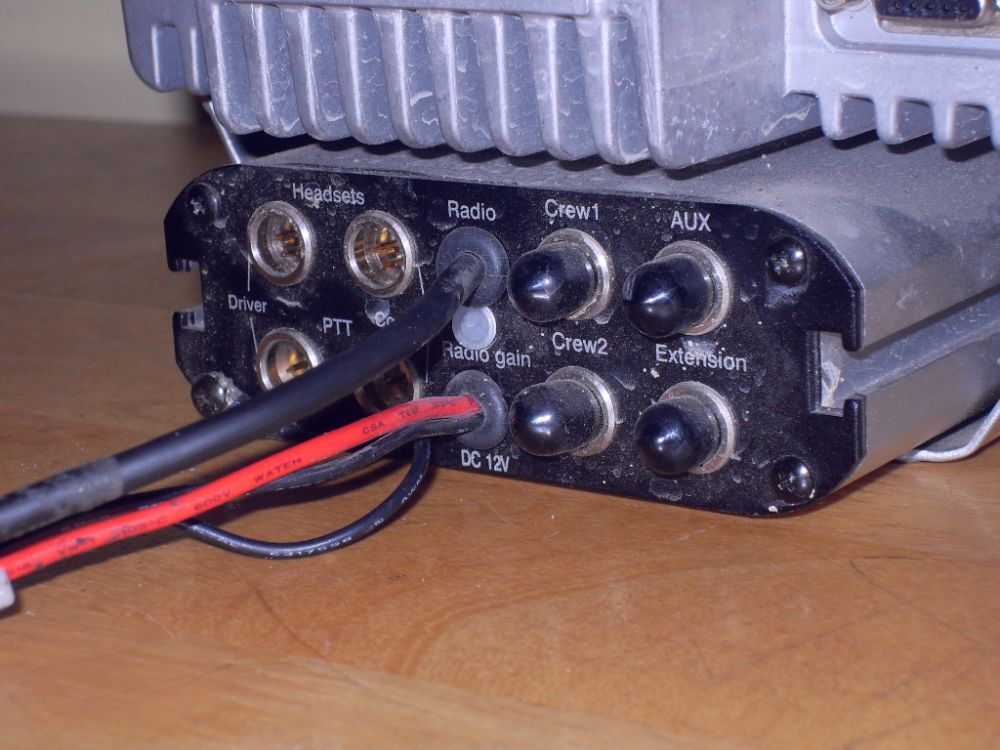 |
Back view from the other side. | ||||||||||||||||||||||||||||||||||||||||||||||||||||||||||||||||||||||||||||||||||||||||
 |
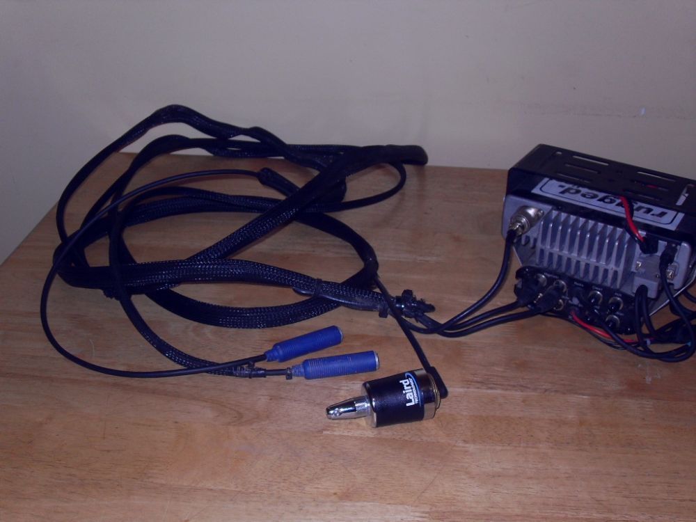
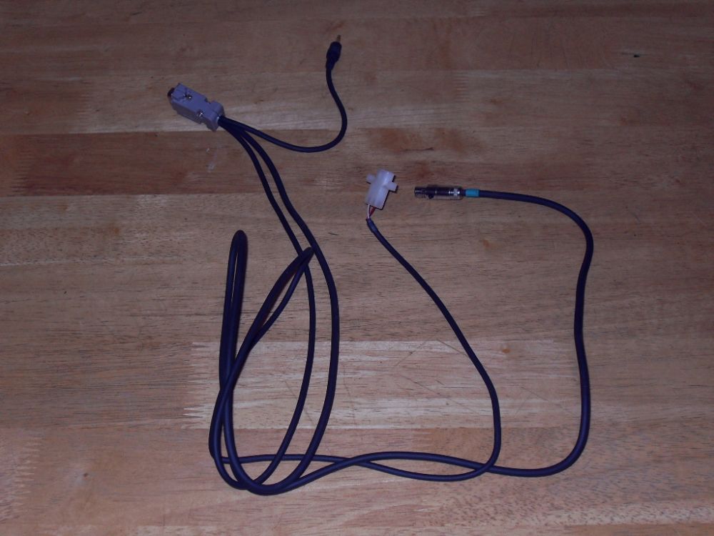
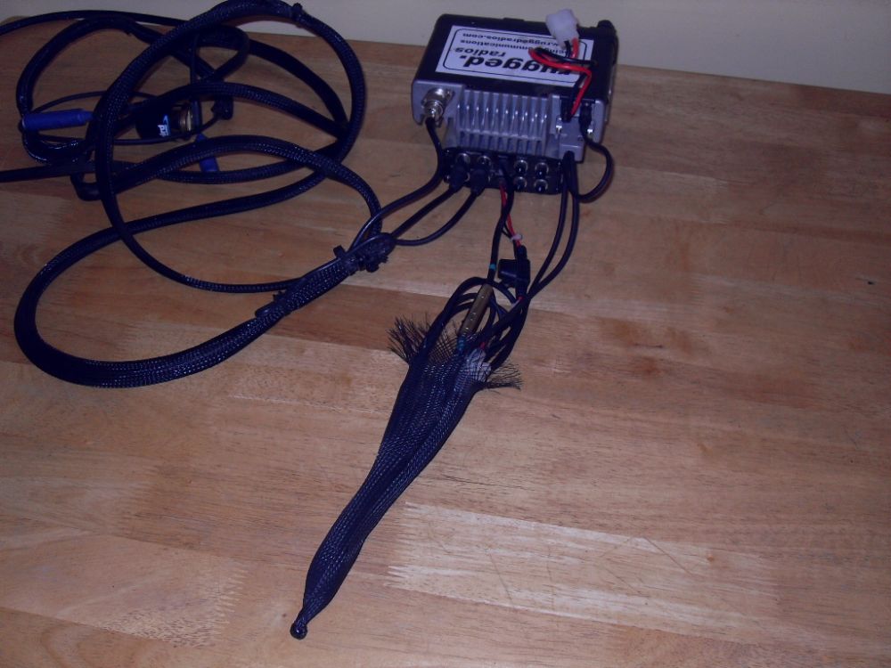
This is the antenna and headset cords harness. | ||||||||||||||||||||||||||||||||||||||||||||||||||||||||||||||||||||||||||||||||||||||||
 |
The antenna wire plugs into the radio with a Type-M (PL-259) 50-Ohm coaxial connection. The headset cords connect to the top two connectors on the left back of the intercom. |
||||||||||||||||||||||||||||||||||||||||||||||||||||||||||||||||||||||||||||||||||||||||
 |
Antenna and headset cords connected. | ||||||||||||||||||||||||||||||||||||||||||||||||||||||||||||||||||||||||||||||||||||||||
 |
This shot shows the radio power & ground wires (on top), the intercom radio integration cord (black with special connector), and and the intercom power & ground wires. | ||||||||||||||||||||||||||||||||||||||||||||||||||||||||||||||||||||||||||||||||||||||||
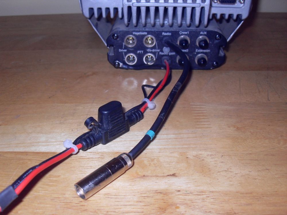 |
Close up of the in-line fuse holder in the intercom power wire, and the intercom radio integration cord's special connector. | ||||||||||||||||||||||||||||||||||||||||||||||||||||||||||||||||||||||||||||||||||||||||
 |
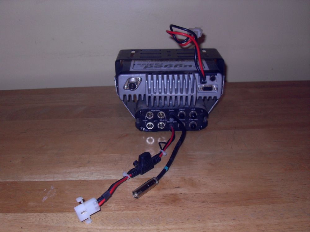
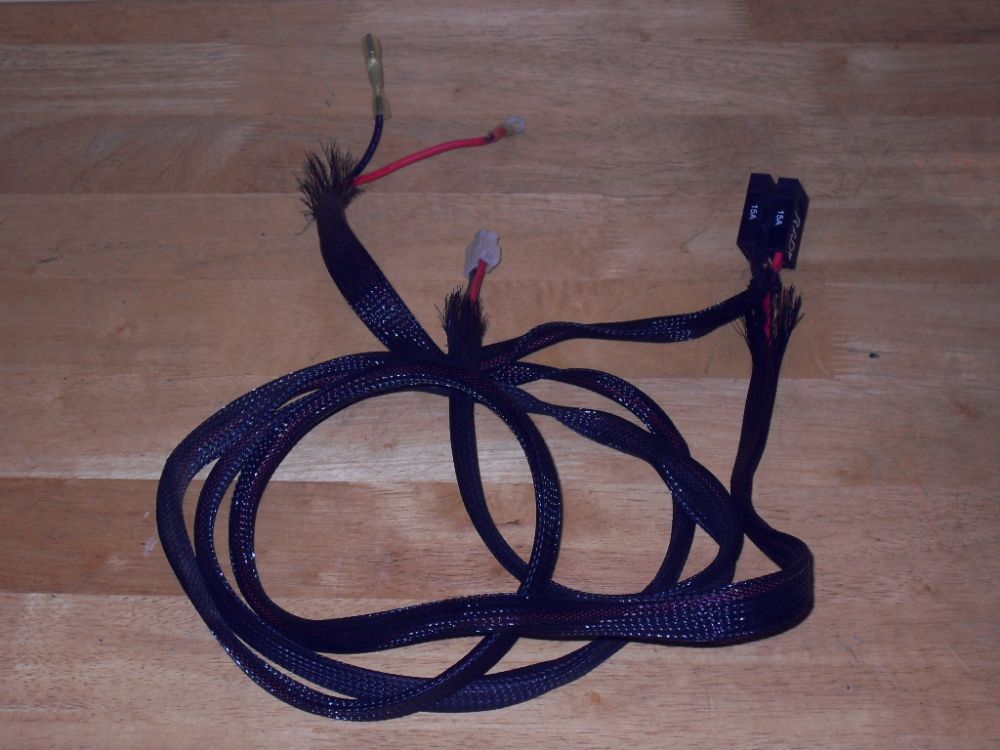
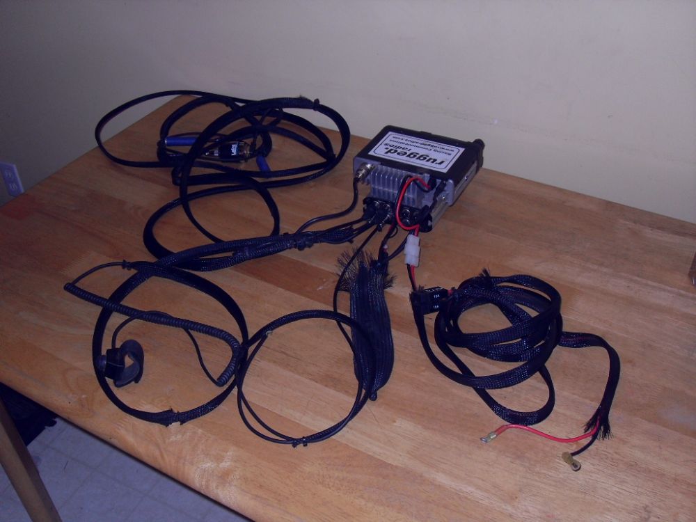
This is the harness for powering the intercom and connecting it to the radio. Note the D-Sub 15-Pin Connector at the top left (grey connector - looks like a computer connector). | ||||||||||||||||||||||||||||||||||||||||||||||||||||||||||||||||||||||||||||||||||||||||
 |
The D-Sub 15-Pin Connector is how the radio and intercom are connected / integrated. | ||||||||||||||||||||||||||||||||||||||||||||||||||||||||||||||||||||||||||||||||||||||||
 |
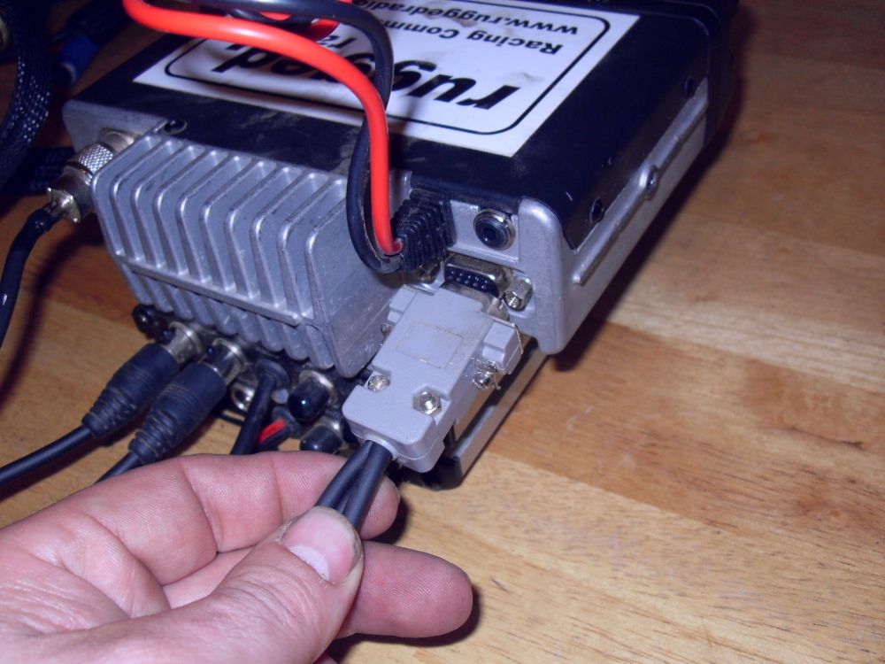
Connect the D-Sub 15-Pin Connector to the radio and tighten the screws. | ||||||||||||||||||||||||||||||||||||||||||||||||||||||||||||||||||||||||||||||||||||||||
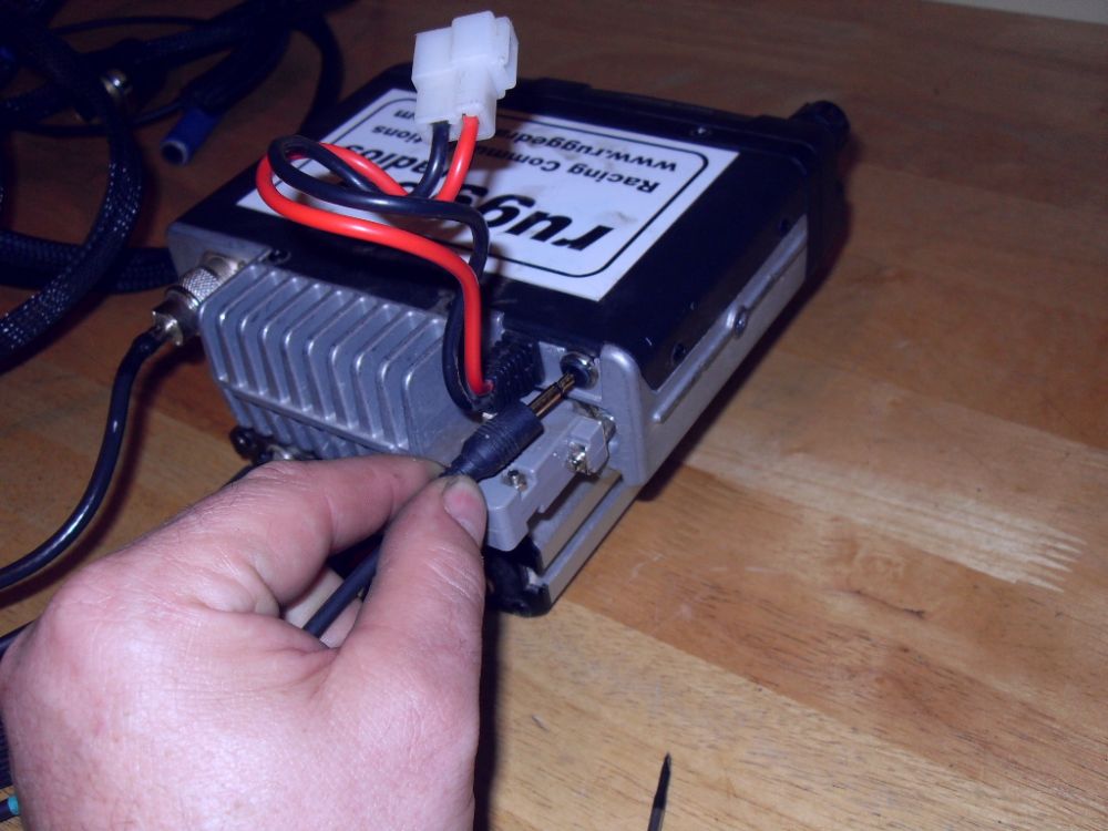 |
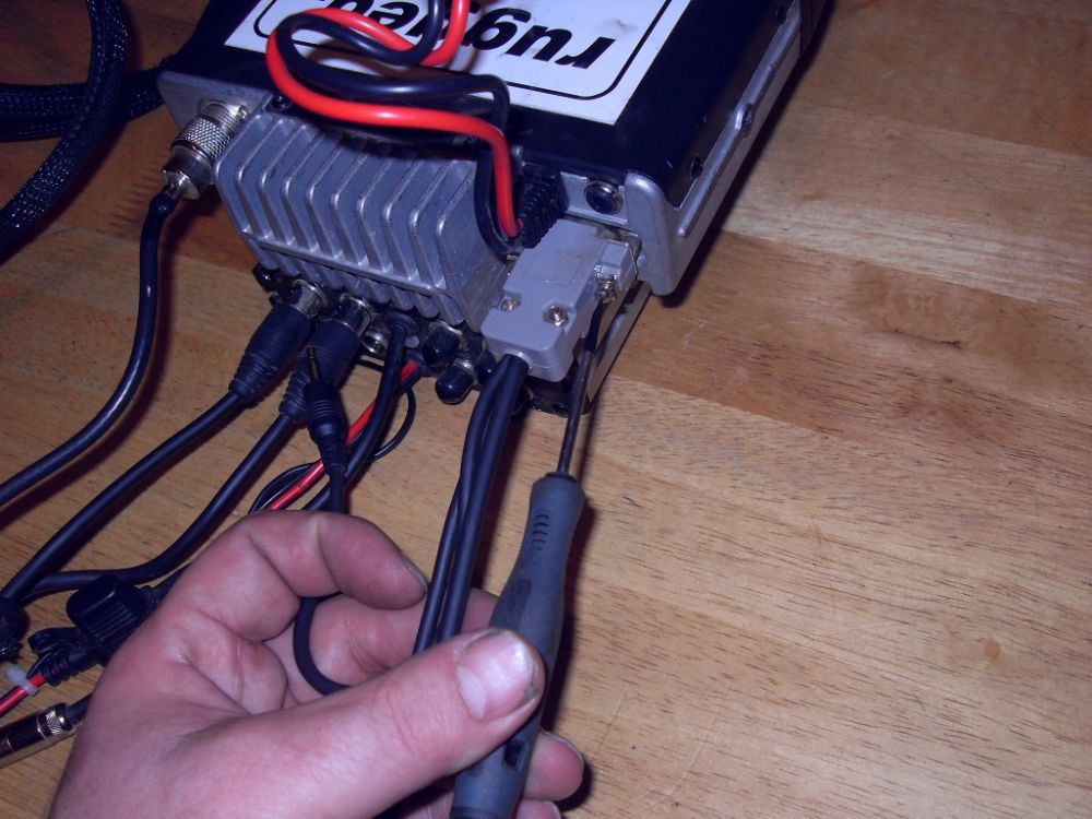
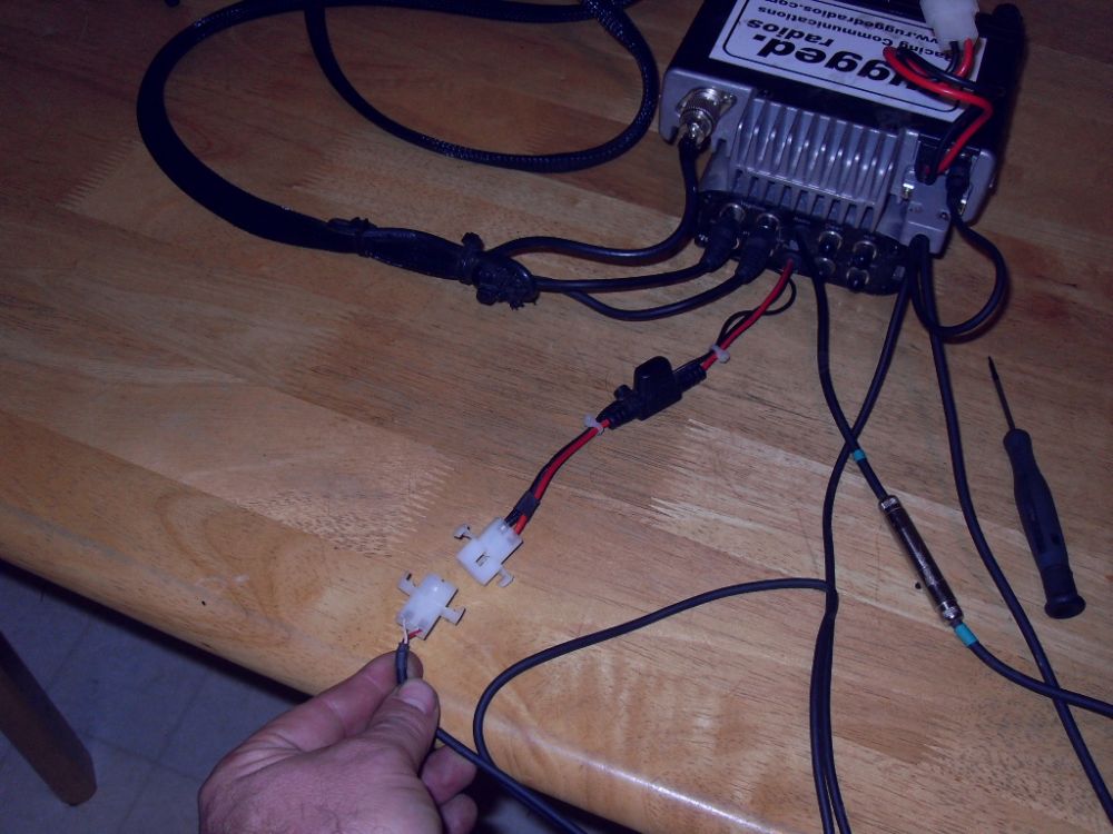
Plug the small pigtail connector into the radio's External Speaker Jack This passes the radio's audio output to the intercom unit, from where it is passed to the headset cords and on to the helmet speakers. If something goes wrong with the helmet or headset cords, in an emergency you can unplug this connection, plug a handheld mic into the front of the radio, and operate the radio stand-alone as you would a CB radio. |
||||||||||||||||||||||||||||||||||||||||||||||||||||||||||||||||||||||||||||||||||||||||
 |
Connect the special connector to the cord coming out of the intercom. | ||||||||||||||||||||||||||||||||||||||||||||||||||||||||||||||||||||||||||||||||||||||||
 |
And connect the white plastic connector to the intercom's power & ground wires. | ||||||||||||||||||||||||||||||||||||||||||||||||||||||||||||||||||||||||||||||||||||||||
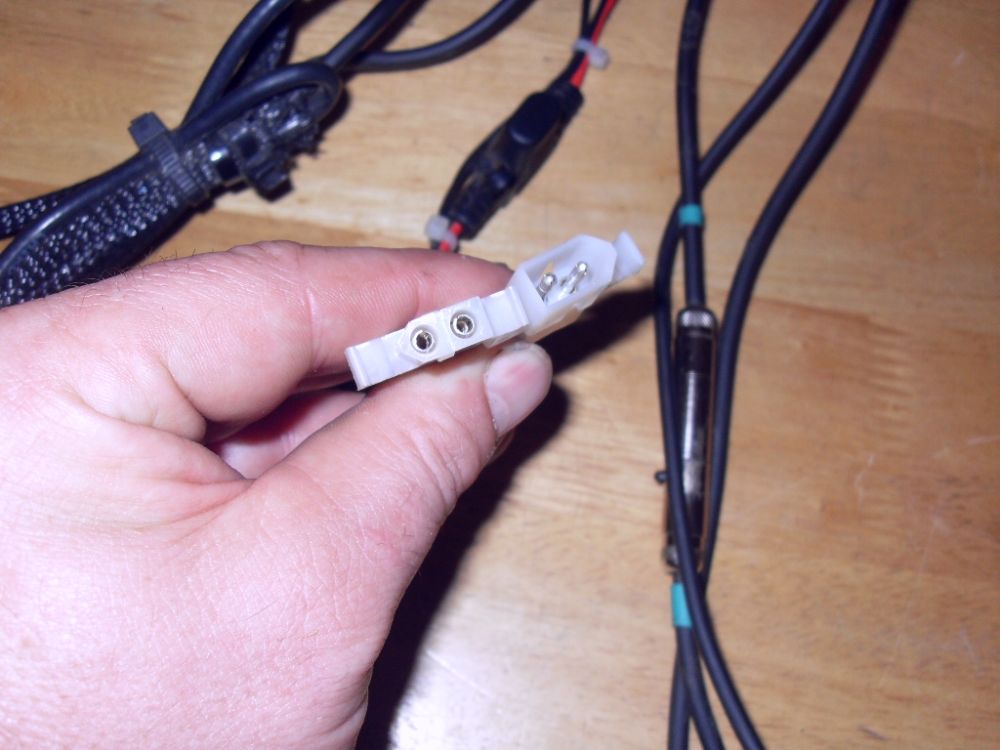 |
The connector only goes together one way because of its shape - so don't force it! | ||||||||||||||||||||||||||||||||||||||||||||||||||||||||||||||||||||||||||||||||||||||||
 |
Here the intercom power and radio integration harness connections are completed. | ||||||||||||||||||||||||||||||||||||||||||||||||||||||||||||||||||||||||||||||||||||||||
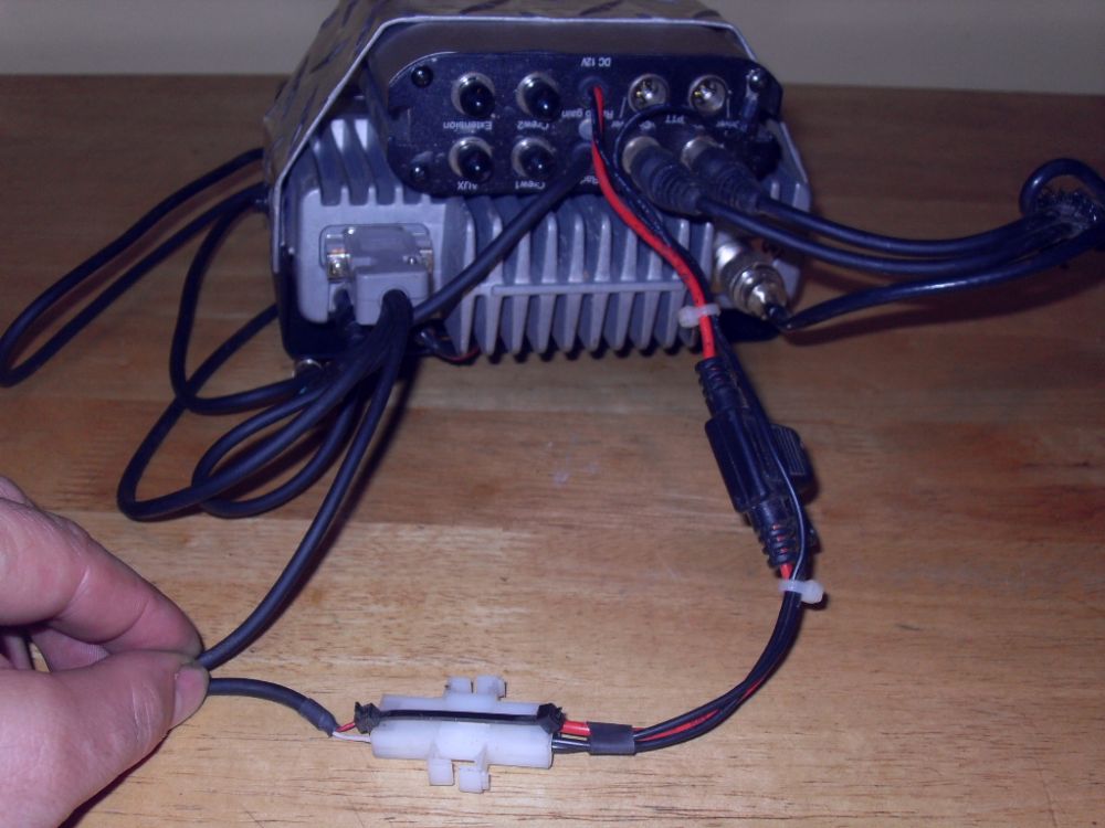 |
We felt the power connection wasn't terribly secure so added a small zip tie to prevent inadvertent disconnection. | ||||||||||||||||||||||||||||||||||||||||||||||||||||||||||||||||||||||||||||||||||||||||
 |
Since the intercom and radio are mounted together in our installation, the intercom power and radio integration harness can be bundled up and secured. | ||||||||||||||||||||||||||||||||||||||||||||||||||||||||||||||||||||||||||||||||||||||||
 |
This is the radio power/ground harness with in-line fuse holders. | ||||||||||||||||||||||||||||||||||||||||||||||||||||||||||||||||||||||||||||||||||||||||
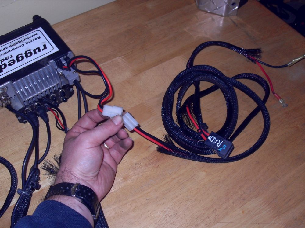 |
Simply connect the plastic connector to the radio's wires and the other end to 12V+DC and ground. Observe correct polarity. | ||||||||||||||||||||||||||||||||||||||||||||||||||||||||||||||||||||||||||||||||||||||||
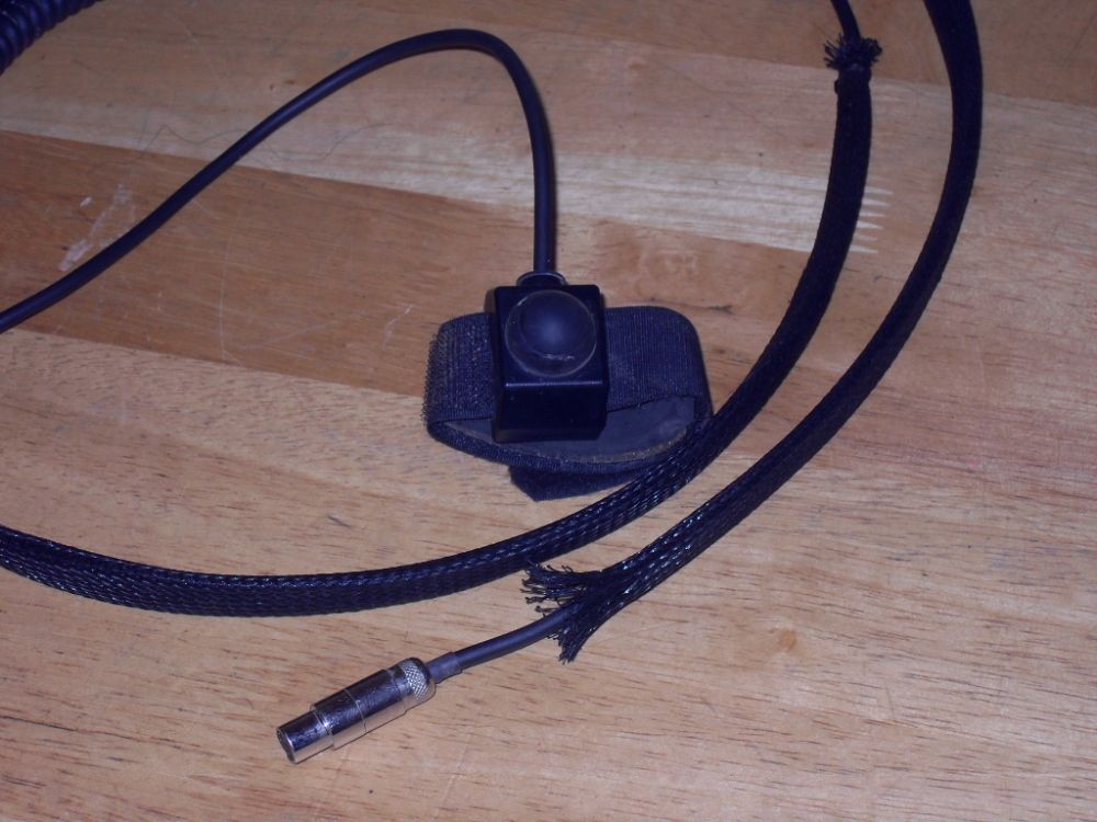 |
This is one of the PTT switches. | ||||||||||||||||||||||||||||||||||||||||||||||||||||||||||||||||||||||||||||||||||||||||
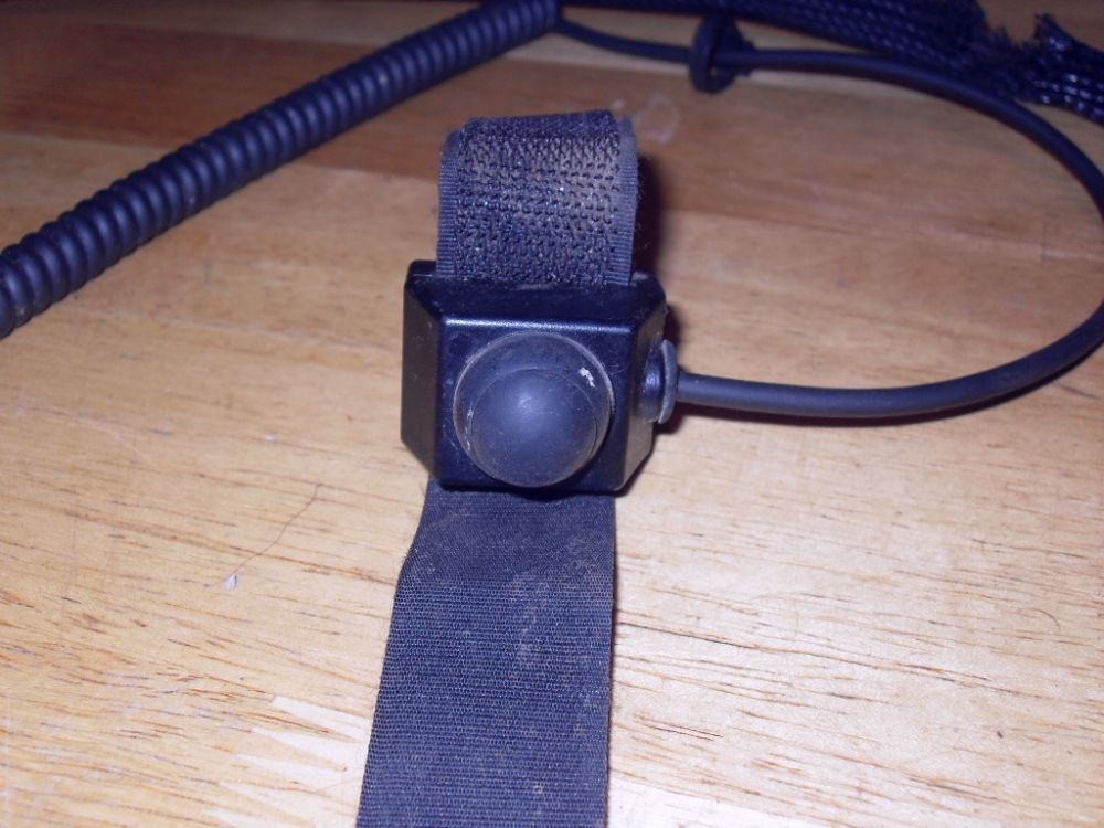 |
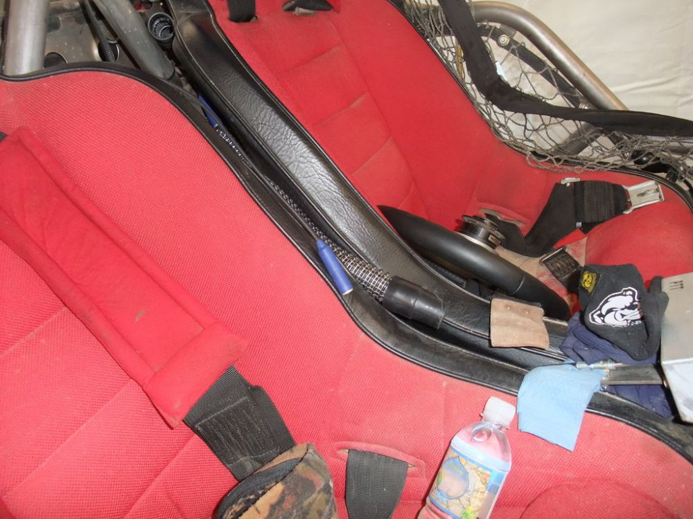
This model is a spring-loaded momentary push button, with a hook-and-loop strap for connection to the desired mounting location (this one is my codriver PTT, which is strapped to my grab-handle). | ||||||||||||||||||||||||||||||||||||||||||||||||||||||||||||||||||||||||||||||||||||||||
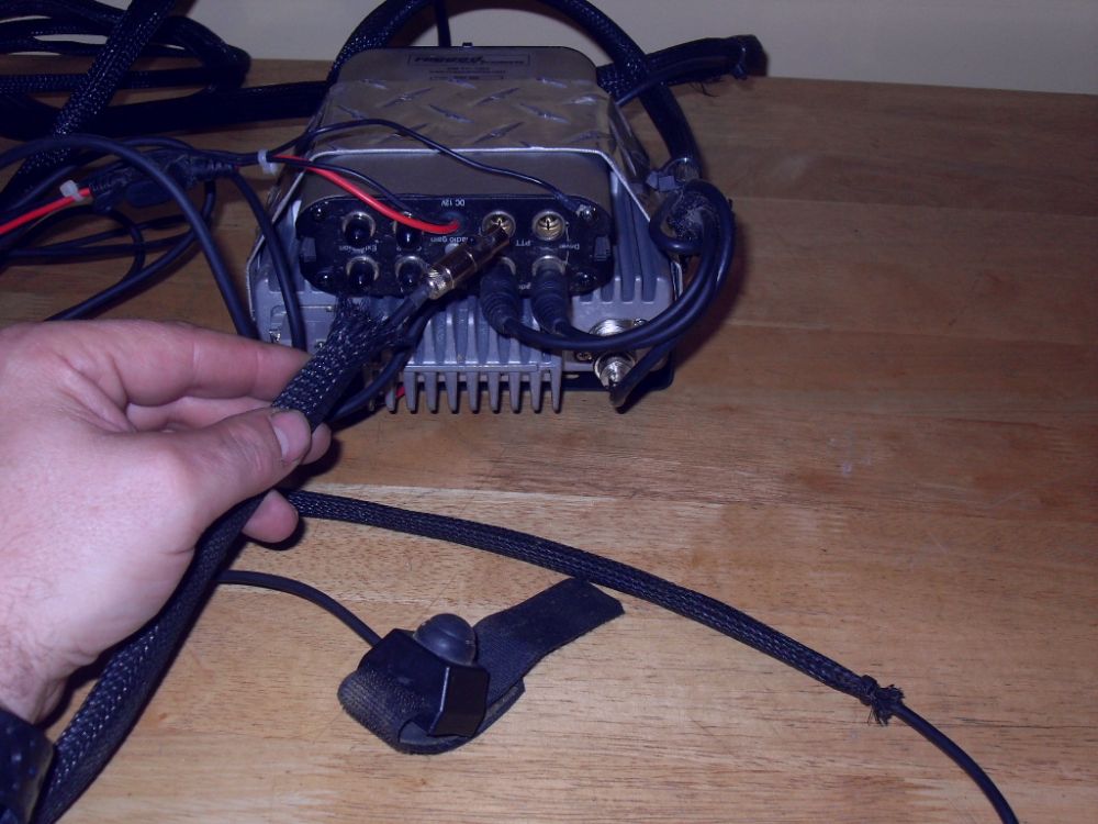 |
Connect the PTT switches to the correct ports on the back of the intercom. | ||||||||||||||||||||||||||||||||||||||||||||||||||||||||||||||||||||||||||||||||||||||||
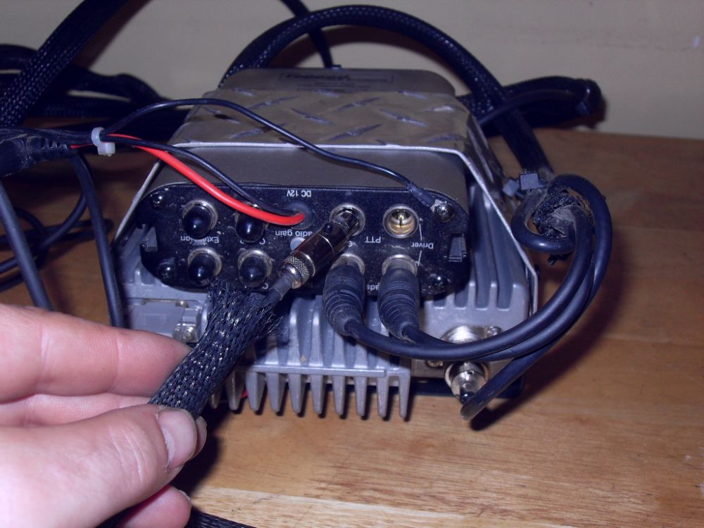 |
The ports and connectors are different from the headset cords, so you can't get it wrong... | ||||||||||||||||||||||||||||||||||||||||||||||||||||||||||||||||||||||||||||||||||||||||
 |
...but make sure you are connecting the right parts and don't force anything. | ||||||||||||||||||||||||||||||||||||||||||||||||||||||||||||||||||||||||||||||||||||||||
 |
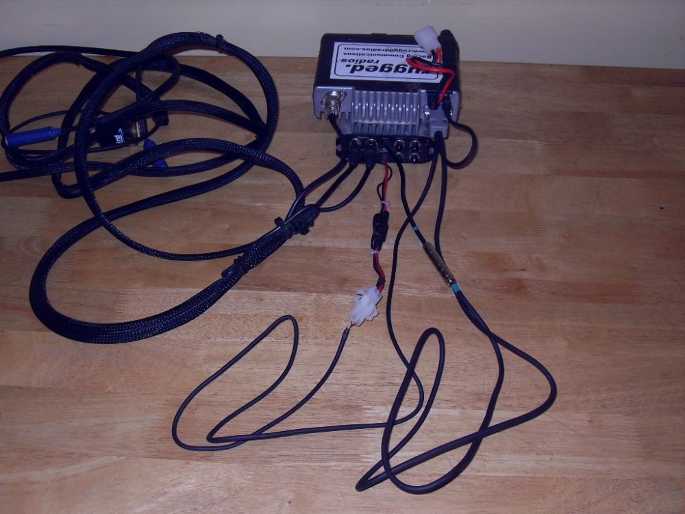
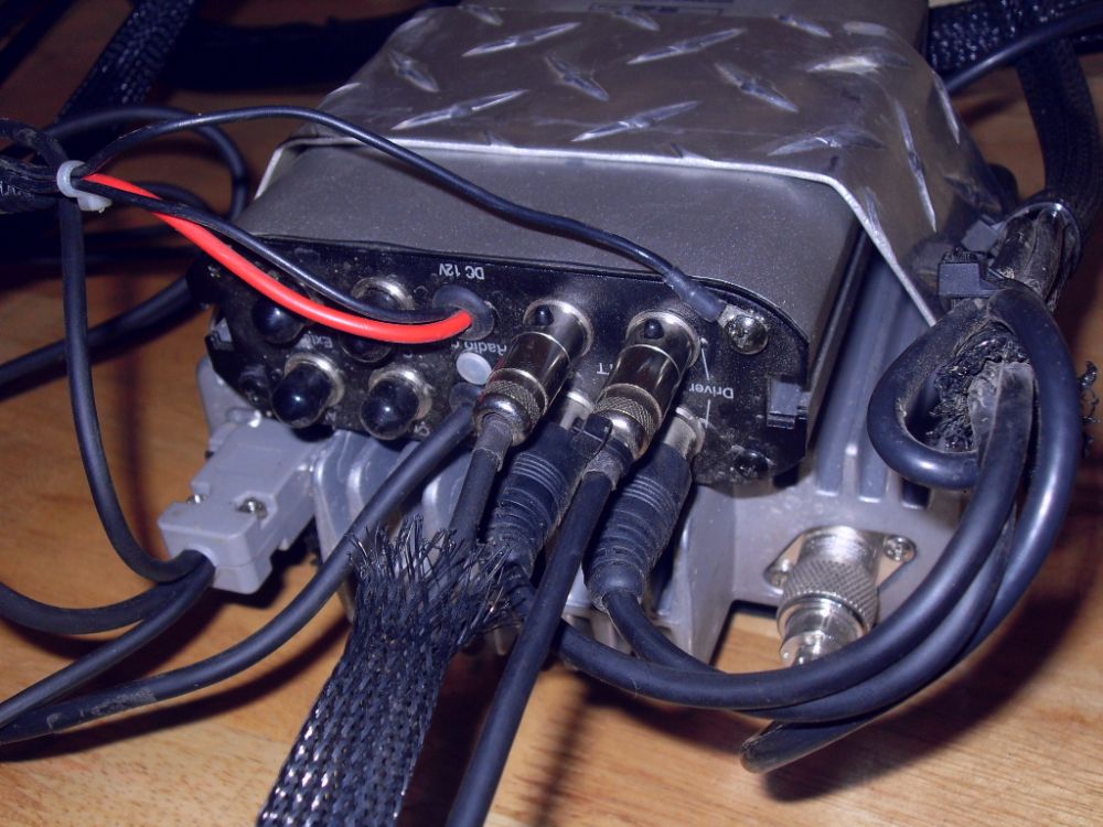
Here the intercom and radio are wired up and ready to be installed. | ||||||||||||||||||||||||||||||||||||||||||||||||||||||||||||||||||||||||||||||||||||||||
 |
The complete package ready to go in the car. | ||||||||||||||||||||||||||||||||||||||||||||||||||||||||||||||||||||||||||||||||||||||||
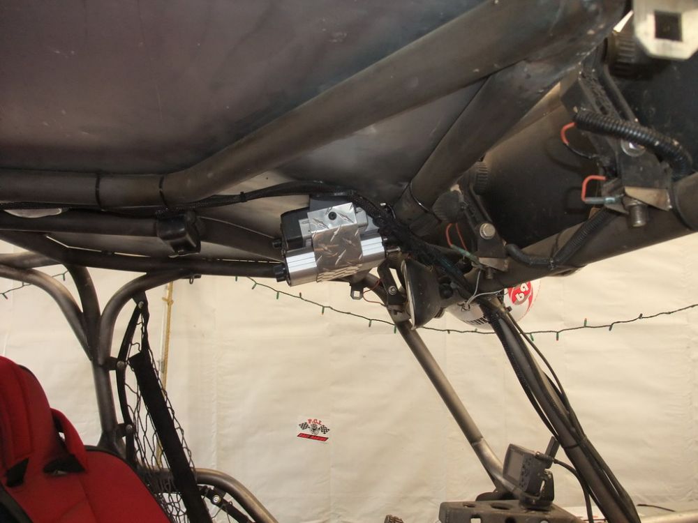 |
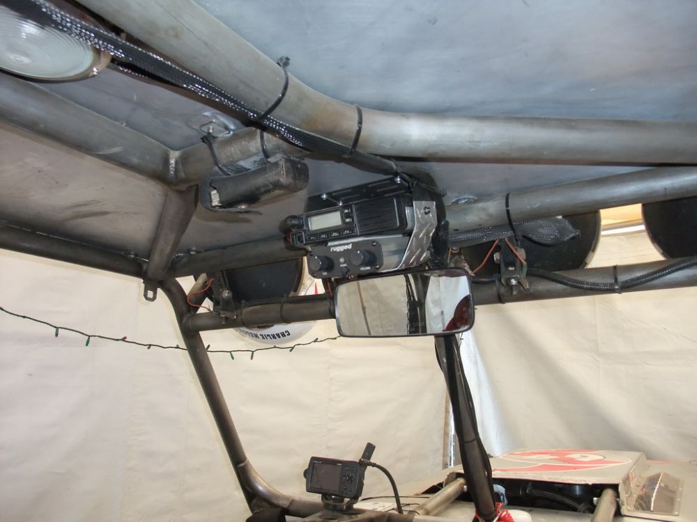
We mounted the units up high, between the driver and codriver. | ||||||||||||||||||||||||||||||||||||||||||||||||||||||||||||||||||||||||||||||||||||||||
 |
Close up side view. | ||||||||||||||||||||||||||||||||||||||||||||||||||||||||||||||||||||||||||||||||||||||||
 |
Here you can see one of the headset cords next to the fresh-air blower hose. | ||||||||||||||||||||||||||||||||||||||||||||||||||||||||||||||||||||||||||||||||||||||||
 |
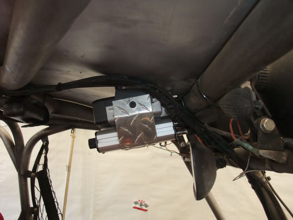
In-car mounted location. | ||||||||||||||||||||||||||||||||||||||||||||||||||||||||||||||||||||||||||||||||||||||||
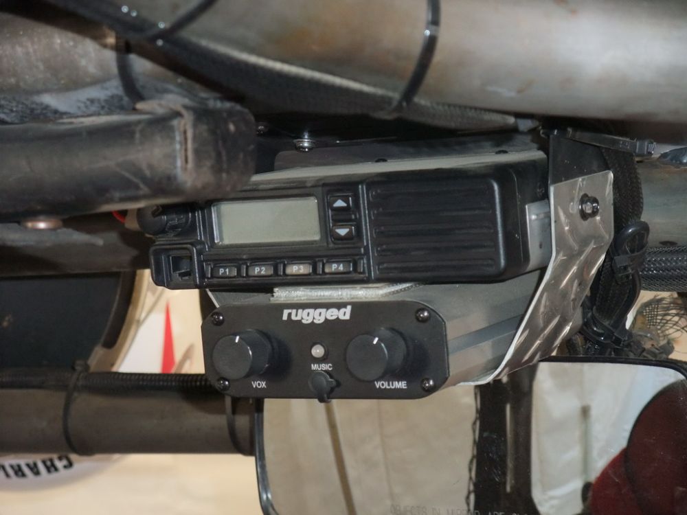 |
Close up. | ||||||||||||||||||||||||||||||||||||||||||||||||||||||||||||||||||||||||||||||||||||||||
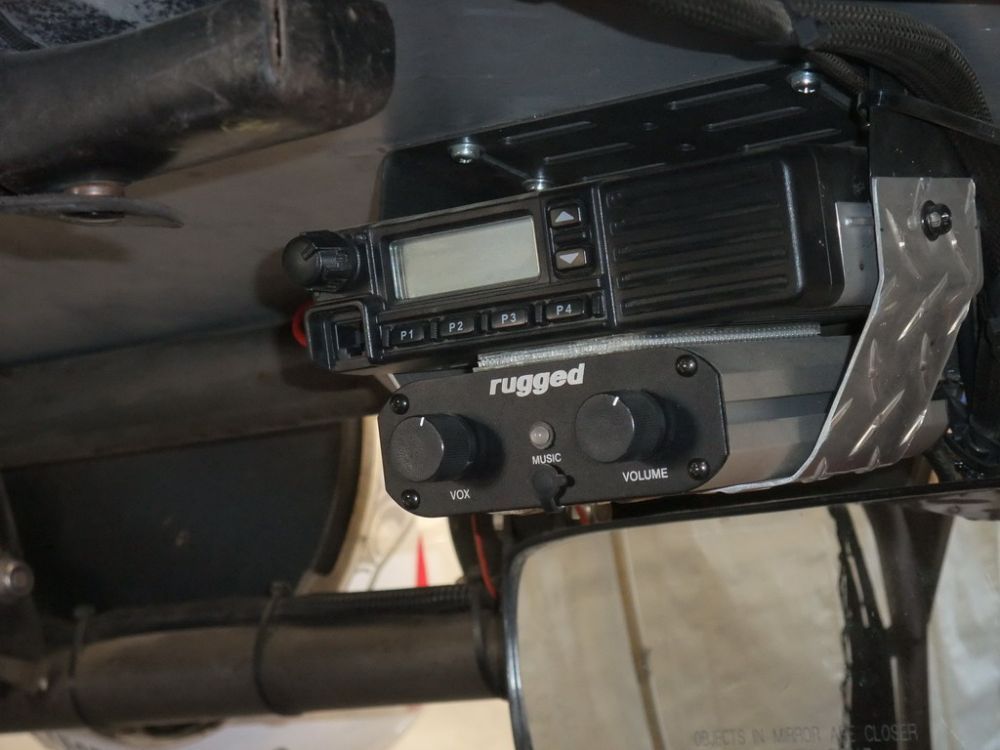 |
Both driver and codriver can easily reach the intercom and radio controls. | ||||||||||||||||||||||||||||||||||||||||||||||||||||||||||||||||||||||||||||||||||||||||
 |
Ready to go racing! | ||||||||||||||||||||||||||||||||||||||||||||||||||||||||||||||||||||||||||||||||||||||||
Basic Voice ProceduresOK, so once you have all your comms gear installed and tested, it's time to learn how to use it like a pro. I know, I know, I can hear the groans already. But believe me, there's a reason professional radio operators talk the way we do - and it isn't just to sound cool in the movies! Many of the reasons that aviation, marine, and other professionals speak in the special way they do are equally applicable to a race situation. These include:
Due to any number of variables, including radio static, a busy or loud environment, or similarity in the phonetics of different words, a critical piece of information can be misheard or misunderstood if proper procedures are not observed when using two-way radio comms. The number one rule of talking on the radio is to stay cool and calm, especially in an emergency. Speak normally and don't yell, scream, or rush. The proper way to communicate via two-way radio is called "voice procedure". Developing good voice procedure is a skill that must be studied and practised, just like any other. The basics of professional voice procedure are: DO’s - Listen out before transmitting; DON'T’s - Speak too loudly; Remember, you are sharing the net with many other users, so be professional at all times! Addressing / CallsignsBecause thee are many simultaneous users (stations) on a radio net, you need to "address" your transmissions. That is, you need to make it clear not only to the station with whom you wish to speak, but also to all other stations on the net, who the transmission is intended for. Similarly, when responding to a call or message, you need to indicate who is replying. We do this using "callsigns" which are really nothing more than a short name or nickname that identifies who you are. For example, our racecar callsign is "Car69". Our main pit crew's callsign is "JFR Ops" (ops is short for "operations"). Our roving pit crew's callsign is "JFR Mobile". Depending on what net you are using, it is possible to use abbreviated callsigns too. For example, if I'm on the main race channel, and need to talk to my pit crew I would use their full callsign: "JFR Ops" so there is no confusion about to whom I am speaking. However, if I'm on our team frequency which we may have to ourselves or share with only one or two other teams, I I may shorten the callsign and just call them "Ops". By convention, the station being called is always stated first, followed by the procedural word (proword) "this is", and then the station calling identifies themself by callsign. For example:
If you hear your callsign being called, but didn't hear who was calling you, the correct response is to reply using the proword "Station calling", as in:
If you need to broadcast a message to everyone on the net, use the callsign "All stations", normally repeated three times, as in:
Common CallsThe three most common radio calls are the preliminary call, the call answer, and the radio check. PRELIMINARY CALL The preliminary call is simply the first or initial call made by a station to initiate a conversation with another station. The preliminary call is nothing more than the callsign of the called station, proword "this is", callsign of the station calling, and the proword "over". For example,
The amount of traffic on the net and the quality of the comms on the net determine how often a preliminary call needs to be used. For example, if you are on a main net with many users, you would always initiate any exchange with a preliminary call. However, if you are on your private net, and comms are good quality, you may forgo the preliminary call and just get straight to the message, for example:
That said, even if you and the station you are calling are the only two users on the net, if comms quality is poor (communications are difficult, broken, etc.) then it is appropriate to begin each exchange with a preliminary call to make sure the station you are calling is ready to receive your message. This is particularly true if you need to send a long message they will have to write down. CALL ANSWER The call answer is simply the initial response by a called station to a preliminary call addressed to them. When you are called by another station you will hear their preliminary call, your response is the call answer which is simply: the callsign of the station calling, proword "this is", callsign of the station being called, and the proword "over". For example:
Before transmitting a call answer, make sure you are ready to receive (copy) the caller's transmission. If you are not ready, or are otherwise occupied, immediately answer and tell the calling station to wait or standby (see applicable prowords and voice procedures below). RADIO CHECKS Performing a radio check before launching on a mission...errm, I mean starting a race or pre-running session is critical. Do not skip it. The radio check serves to:
The former is obvious, but the latter is also important as it determines "message transmission speed" (i.e. how fast you can speak on the net), along with how strict your voice procedures need to be, how long or formal your callsigns need to be, etc. While I always advocate for strict voice procedures and utmost professionalism at all times on any net, I recognize that not everyone shares my passion for procedure. However, if the net is congested, noisy, or otherwise poor quality, it is to your utmost advantage to be strict with your voice procedures as this will enable you to communicate as clearly and effectively as possible with as little repetition as possible. Remember, this is very important because the net is not yours - it is a shared resource. Good procedures will help you avoid "stepping on" other people's transmissions, clogging the net with garbage talk, and otherwise pissing off your fellow racers who are also trying to communicate in challenging conditions. So do your radio checks, mmmkay. Now, "Hey Bubba, you got ya ears on?" is NOT a proper radio check! A radio check is initiated by one station as follows: station being called, proword "this is", callsign of the station calling, proword "radio check", and the proword "over". For example:
The correct response to a radio check is a report of strength and readability, as follows: Report Of Signal Strength
Report Of Signal Readability (clarity)
Therefore, a complete radio check would be:
Technically, signal strength and readability can be reported in any combination (but always in the order strength then readability), but obviously certain combinations don't make sense. For example, you're unlikely to hear "very weak and clear". Note that both scales are numbered from one to five, where one is the worst and five is the best. It is therefore possible to report a radio check by number instead of prowords, in which case the numbers are separated with the word "by". For example "Five by five" is the numerical equivalent of "loud and clear". Personally, I don't favour this method, as the numbers don't immediately convey the information required and you have translate them into the words in your head to understand something meaningful. For example, 3 x 2 doesn't mean a lot to me intuitively, but "weak with interference" does. Finally, it is perfectly acceptable to simply substitute the proword "roger" for "loud and clear", in which case the above full radio check can be abbreviated to:
ProwordsThe foundation for developing professional voice procedure is the use of certain special words or phrases, called "prowords". This is the "radiotelephone vocabulary" referred to in the previous list of "DO's". Use these prowords to communicate clearly, effectively, and quickly. Basic Prowords
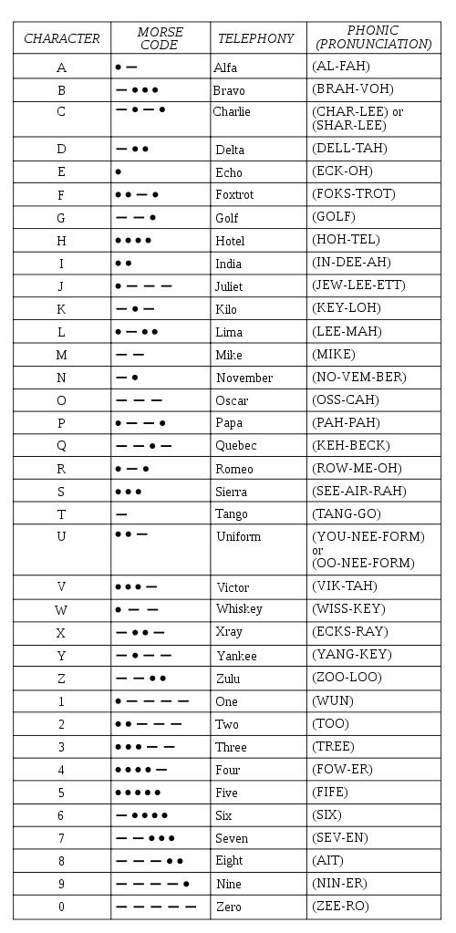
Phonetic AlphabetThe phonetic alphabet is used to spell words using a unique, easily distinguished word to represent each letter of the alphabet. This is done to reduce the chance for misunderstanding and reduce the need to repeat things since audio quality may be poor and many letters can easily be confused with others. The phonetic alphabet is as follows:
RelaxationsDepending on the net in use, the number of stations on the net, the quality of the circuit, and the tactical situation (how quickly you need to transmit and receive, it is possible to relax from full formal voice procedures. For example, if the net is very busy, brevity and speed are usually the chief concerns and some risk of loss of clarity can be accepted. If, on the other hand, the net is not busy but ranges are long, quality poor, and information critical, then more formal procedures are called for. The following examples demonstrate three different levels of formality used in sending the same message, which is the pit crew asking what time the car will be at pit stop two and the car replying. Formal:
Relaxed:
Super relaxed:
USING MAYDAY TO TRANSMIT A DISTRESS CALLAircraft and ships use a standardized method of transmitting a distress message that enables the maximum amount of information to be conveyed in the shortest time possible. It also enables distant stations to receive and understand the information, even when clarity is low. Now, in the case of aircraft and ships at sea, this is extremely important as it may be the last anybody hears from them until (if) a search and rescue party is able to locate them. Things are probably not so critical in offroad racing, but then again, if you're lost and alone in the desert, it's probably a good idea to communicate in a proven, professional manner. Using procedure also helps to keep you calm in stressful situations so you don't end up yelling or rambling incoherently into the mic and not helping yourself. The distress call consists of:
Example: "Mayday, mayday, mayday, this is Car69, Car69, Car 69. Position race mile 63, Time 15:30 local, Car overturned and on fire, minor injuries to crew, remaining with car, over" OK, I could go on and on forever about comms and comms procedures, but before I start quoting classified tactical radio comms procedures and going on about tropospheric ducting of signals, we'd better call it a day. Once you have your kit installed and your voice procedure down, that's not the end. The smart tactical racers and their crews will develop their own comms plan which may include things like:
Perhaps that might be the subject for another article one day! |
|||||||||||||||||||||||||||||||||||||||||||||||||||||||||||||||||||||||||||||||||||||||||
|
|||||||||||||||||||||||||||||||||||||||||||||||||||||||||||||||||||||||||||||||||||||||||

|
Sources: Rugged Radios 3621 Sacramento Drive #1 San Luis Obispo, California 93401 |
|