 |
Mobile Home Trailer Axles By Bill "BillaVista" Ansell |
IntroductionMy first-ever trailer was a rough old home-built piece of junk with what, at the time, I called "wierd, 5-bolt wide-pattern wheel thingey" axles. I found out later that they were mobile home axles. Turns out, many home-built and construction-site trailers use mobile home axles as they are cheap and strong and often come with brakes. The drawback is, they are not really designed (and may not be legal in your area) for long-term use. This means thay are not assembled with service in mind, and replacement parts can be hard to come by. |
 |
| There's also not a lot of tech info out there available for them. I can't do anything about the design, or the availability of parts, but I can share what i learned about them while I was running them. | |
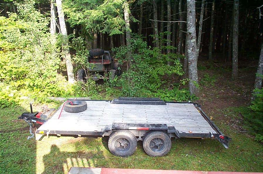 |
This is what my first trailer looked like. Built in Cape Breton by a coal miner, from scrap metal taken from a WWI battleship. |
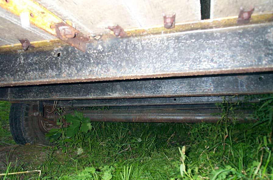 |
Mobile home axles underneath. |
|
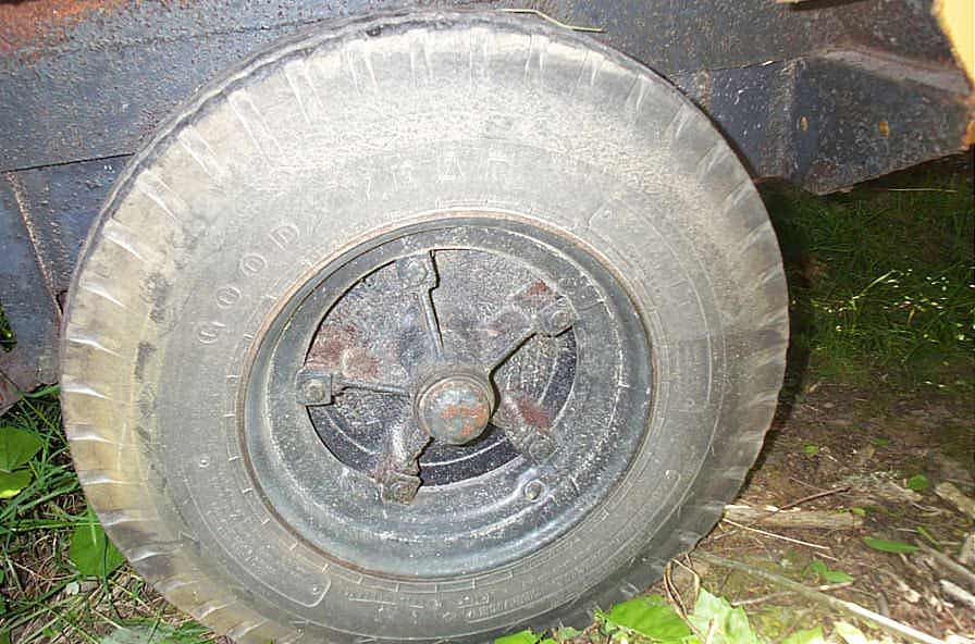
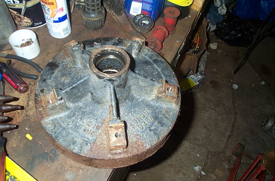
This is what the wheel and hub look like assembled. Let's tear it down and look at the brakes and bearings. |
Disassembly |
|
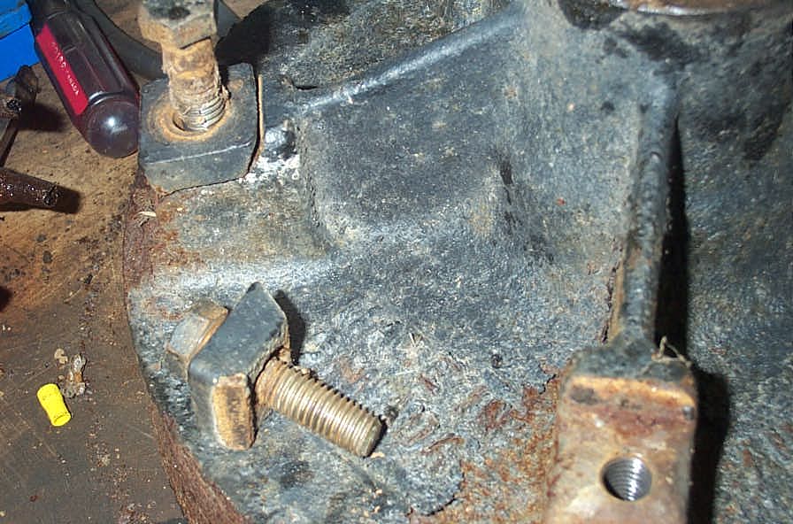 |
The first step is to remove the wheel bolts and little wedge blocks that clamp the wheel onto the hub. This close-up shows how it works. |
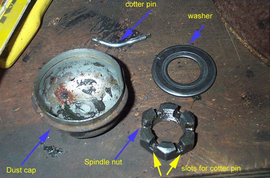 |
Once the tire and rim are removed, you pry off the hubs' grease cap with a screwdriver, and here's the hardware you have to remove to remove the hub. It's simply a cotter pin, castellated nut, and washer that bear on the outer wheel bearing. Remove cotter pin, nut, and washer and the outer bearing falls out and the hub slides off the spindle. |
 |
You prob can't see it in the pic, but something I found really interesting, is that the hub/brake drum assembly has a maximum diameter figure cast into it, the type you see on normal automotive drums and rotors specifying the limits to which they can be machined during overhaul. Now, if these axles are indeed intended to be one-time use only hauling a mobile home one way....then why would this be so? I'm having a hard time picturing a mobile home being hauled so far that along the way, you'd have to stop, remove the home from the trailer, remove the brakes, have the drums machined, reload everything and carry on. Weird huh? |
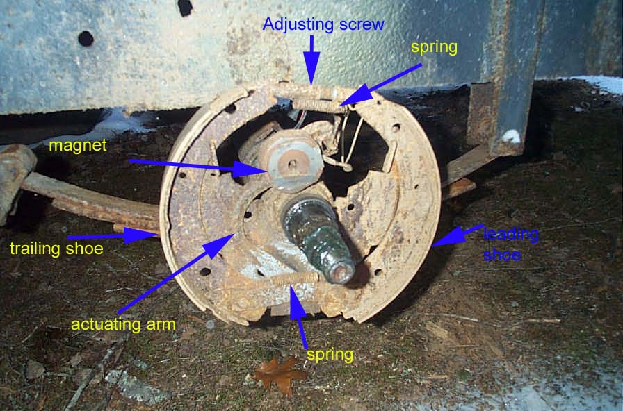 |
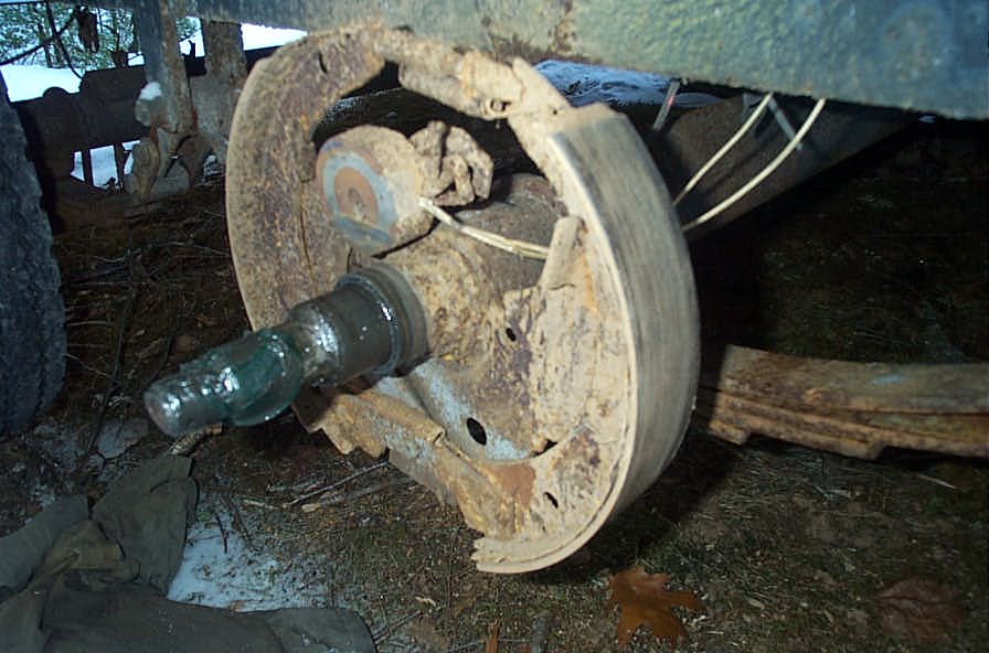
Under the hub is the brake assembly. Pretty standard drum brake components, at least in function (I haven't checked dimensions for replacement possibilities). |
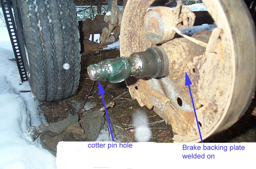 |
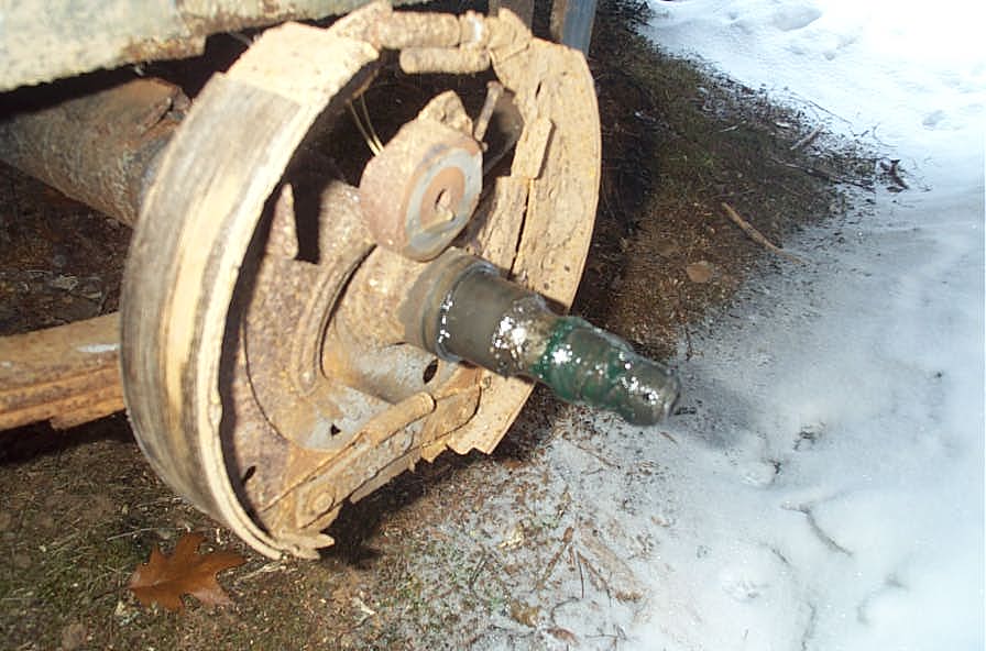
However, note that in this pic, the brake "backing plate" is welded - not bolted to the axle tube, so replacement of the whole brake assembly (rather than individual parts) will require creative fab work. Pic also shows the hole in the threaded spindle through which the cotter pin slides. |
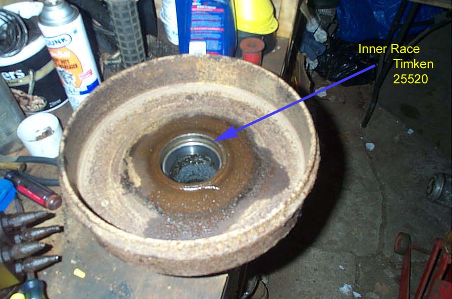 |
back side of the hub / brake drum assembly showing the inner wheel bearing race. |
Bearings |
|
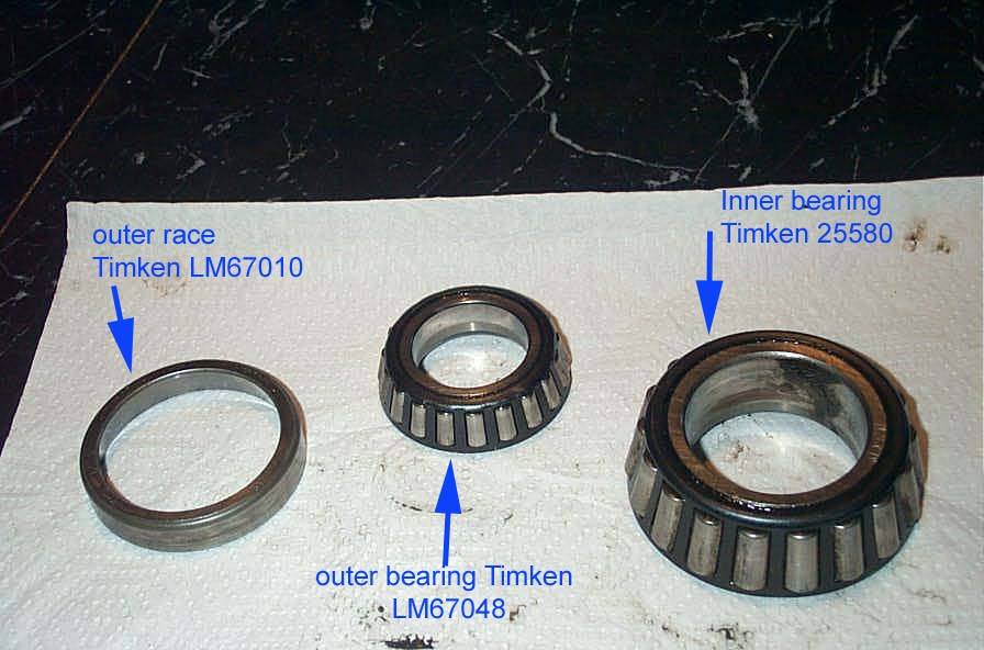 |
Here are the wheel bearings, with Timken numbers.
I had read that these bearings were non-replaceable or non-serviceable. Well, they are certainly available, you can order them by part number from any good bearing shop. Alternatively, the chart below gives some applications you can quote to the guy at the parts counter to get the same bearing (info taken from www.timkeninfo.com) . The prices I was just quoted (Mar 2003) by my local suppler, in Canadian $, are Outer bearing - Timken LM67048 - $8.65 Outer race - Timken LM670101 - $4.19 Inner Bearing - Timken 25580 - $18.10 Inner race - Timken 25520 - $9.10 |
At first I was concerned that they may be considered "unserviceable" due to the manner in which the bearings and hub are retained. That is to say, I can foresee problems setting the proper wheel bearing pre-load because of the lack of adjustability with the single-nut-and-cotter pin setup. Particularly if you look at the large distance between the slots in the castellated nut in pic#3 above. There's obviously a pretty limited range of adjustment, because of this large gap, because if it's not quite right, you have to either tighten down or back off the nut quite a lot (in big steps) to reach the next slot through which you can fit the cotter pin. Turns out my fears were unfounded and that this assembly / arrangement is extremely common on all types of trailer axles. See below for a couple of procedures on how to adjust them. The short story is, screw on nut to finger tight, while rotating hub. Continue rotating hub while tightening another 1/4 turn or so to seat/preload bearing. Back off nut till loose. Screw up finger tight again, then back off to the first slot where you can install the cotter pin. A little more research also turned up the fact that the bearing combo of inner 25580/25520 and outer LM67048/LM670101 is also very common on 6 and 7000 lb trailer axles. You can find these bearings at any trailer supply house. Here's the bearing apps, should you need them:Outer BearingLM67048 $8.65 Applications1988-2002 Camaro 2.8, 3.1, 5.0. 5.7 Warner T5, T5 World Class; 5 Spd.; frontCone 85-86 Mercury Capri 2.3, 3.8, 5.0 Warner T5, T5 World Class; 5 Spd.; frontCone 1988-2000 Pontiac Firebird any engine 5 Spd.Cone Outer raceLM67010 $4.19 ApplicationsFORD 1984-85 ESCORT 1.6, 1.9, 2.0, ; MTX-III; 5 Spd.Cup CHEVROLET 1993-02 CAMARO 3.4 3.8 5.7 Warner T5, T5 World Class; 5 Spd.; frontCup FORD 1984-94 ESCORT GT 1.8 MTX-III; 5 Spd.Cup FORD 1986-90 TAURUS MTX-II; 4 Spd.Cup FORD 1984-94 TEMPO GL MTX-III; 5 Spd.Cup PONTIAC 1988-2000 FIREBIRD ; 5 Spd.Cup Inner bearing25580 $18.10 ApplicationsPLYMOUTH 1965 BELVEDERE L6 3.7 3687 Exc. Station Wagon and Taxi; Cone PLYMOUTH 1966 BELVEDERE L6 3.7 3687 Exc. Station Wagon and Taxi; Cone , differential bearing PLYMOUTH 1966 SATELLITE L6 3.7 3687 Exc. Station Wagon and Taxi; Cone Inner race25520 $ 9.10 ApplicationsPLYMOUTH 1966 BELVEDERE L6 3.7 3687 Exc. Station Wagon and Taxi; Cone , differential bearing FORD 1970 LTD V8 5.0 9.375" ring gear: WDR, WFH axles; Cup DODGE 1967 W100 SERIES V8 5.2 8.75" ring gear: 1.75" pinion shaft OD; Cup Wheel bearing adjustment procedures:Method 1
Method 2If the hub has been removed or bearing adjustment is required, the following adjustment procedure must be followed:
Brakes |
|
 |
As you can see - all my brakes turned out to be complete junk. |
 |
About the Mobile Home axle brakes. I also discovered that mine are 12"x2", and that this is a common size on 6 and 7000lb conventional trailer axles. At first, I figured, there's probably no reason I can't fit "regular" 12x2 brake shoes, springs, and the little star adjuster on my mobile home welded-on backing plate. However, I was not able to verify this for sure because, by the time you add up the cost of shoes, springs, adjuster, and magnet...you end up only $12 less than the cost of a complete 6000lb axle brake assembly - already assembled (no messing with those awful springs) on a backing plate with new magnet. Yes, this backing plate is designed to be bolted to the flange on a regular trailer axle, but it will be simple for me to adapt. I shall simply cut and grind the old backing plate off, make a 1/8" square steel flange drilled to match the new backing plate, slide it on the tube. Bolt the backing plate to it, install and adjust hub, slide brakes to right position, square everything up (I'm lying here - I'll prob. just eyeball it as usual), and weld on the custom flange. Certainly can't be any harder than a custom disk brake conversion on a 4x4 and I've done a few of those. |
TiresAfter running the trailer for a while, I finally bit the bullet and bought new tires. It was a difficult decision to dump so much cash on brand new tires in such an odd size. However, I was convinced it was the right decision for the following reasons: In my recent research I have read a lot of articles and stories about how it is essential to run properly rated trailer tires when towing a heavy load like 7-8k lbs. Regular passenger car/truck tires do not have the required sidewall strength and using them leads to dangerous blowouts. Considering how tough the tires are - Goodyear, bias ply, 7 ply tread, 8 ply sidewall, and how much I'll use the trailer, and that the last set were probably original and on there since the mid 70s, they should last me about forever. While an odd size, the local Goodyear commercial tire place has them in stock, so they can't be that rare or odd I've read to may towing horror-stories to cut any corners with the towing gig. These are the right tool for the job, safe, and are probably not that much, if any more expensive than similarly rated 15" trailer tires of equivalent quality. Total bill came to $594 Cdn for four installed, new valve stems (metal), old tire disposal fee, and taxes. |
|
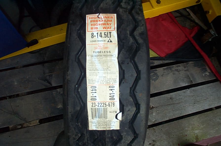 |
Here's the sticker. Made in Brazil...hey those guys sure should know their rubber....it grows there after all. Yep - that says load range F !! |
 |
Here they are in all their glory |
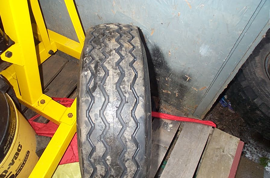 |
Not the sexiest tread, but reminds me of a lot of long-haul 18-wheelers....a good sign |
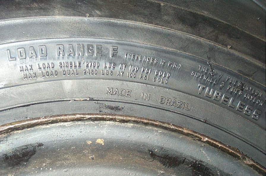 |
WOW - look at that capacity. 2790 lbs each at 100 psi!! |
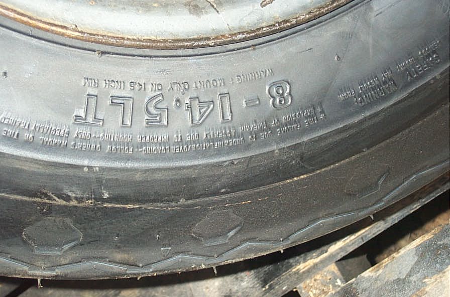 |
See, I wasn't kidding - they're 8-14.5 |
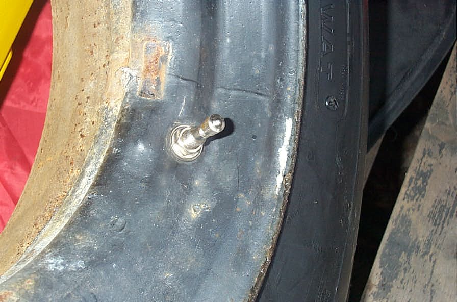 |
Fancy new valve stems. |
|