 |
D44 Hy Steer
By Bill "BillaVista" Ansell |
IntroductionThis article is about custom Hy Steer for Dana 44 front axles. "Hy Steer" is the coloquial term for a steering arrangement that places the steering linkage above the leaf springs, attached to steering arms on the top of the knuckles. |
 |
The article is composed of the following five parts:
Part 1 - ResearchDefinitions:Hy Steer - a steering linkage setup where both the draglink and tie rod are located above the springs. Crossover steering - a steering system where the drag link and tie rod attach independently to the passenger side knuckle Inverted T - a steering system where the tie rod attaches knuckle-to-knuckle, and the drag link attaches to the tie rod, usually near the right hand side. Inverted Y - a steering system where the draglink attaches to the passenger knuckle, and the tie rod mounts from the draglink to the drivers knuckle. |
|
 |
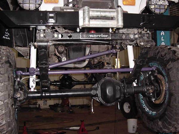
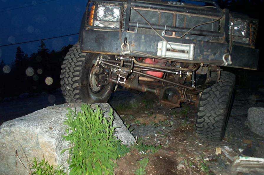
This is a combination crossover and Hy Steer setup. | ||||||||||||||||||||||||||||||||||||||||||||
 |
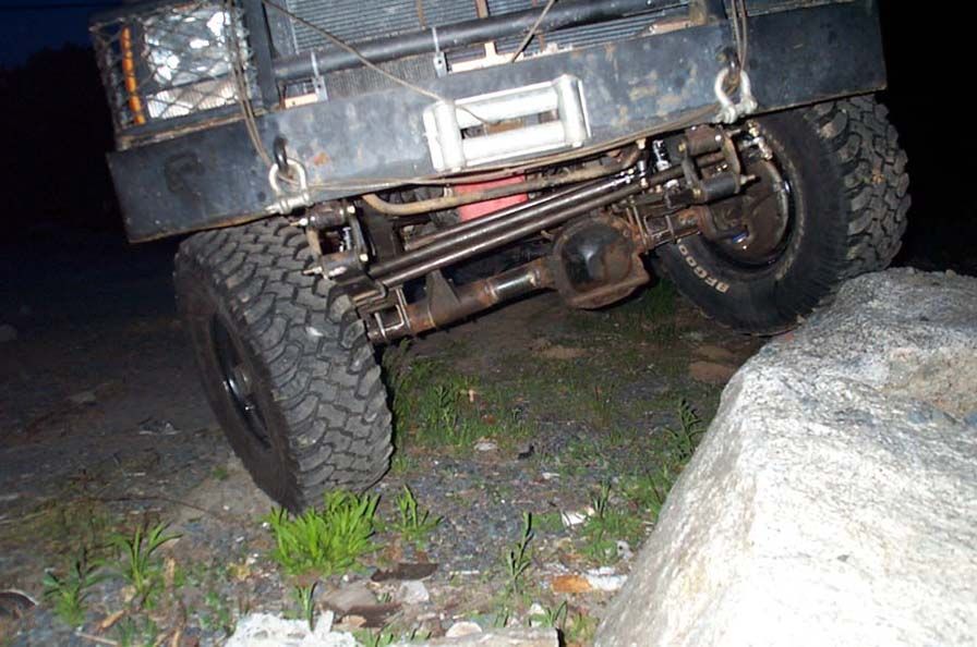
This is a
Hy Steer Inverted T
Photo: Ron Hollatz |
||||||||||||||||||||||||||||||||||||||||||||
 |
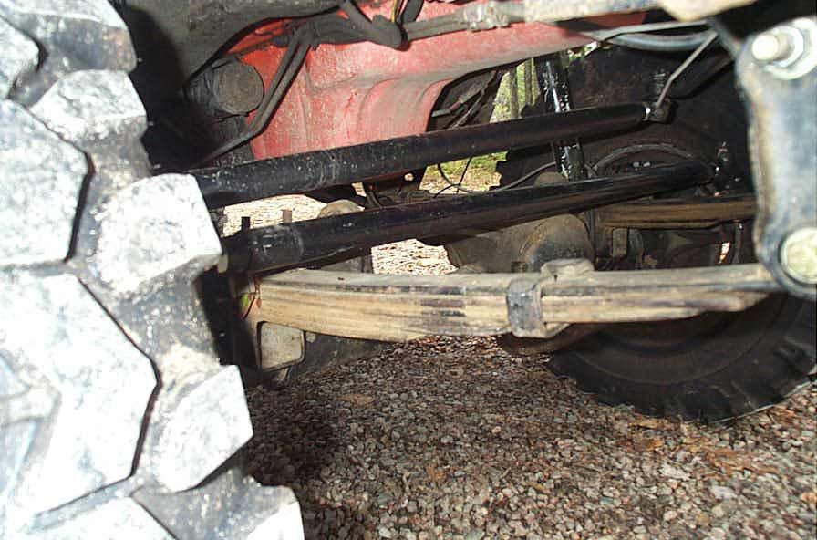
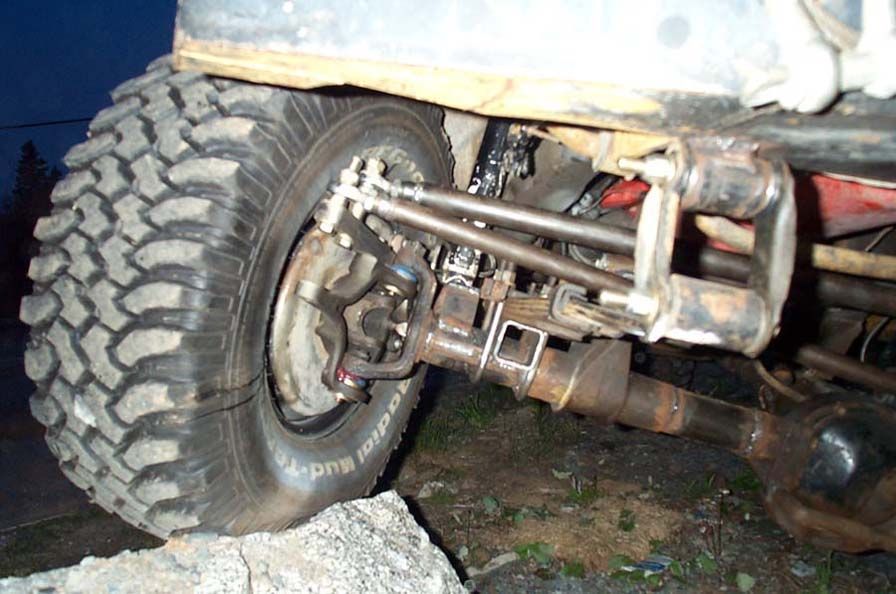
This is an Inverted Y (and a horrible one at that!) | ||||||||||||||||||||||||||||||||||||||||||||
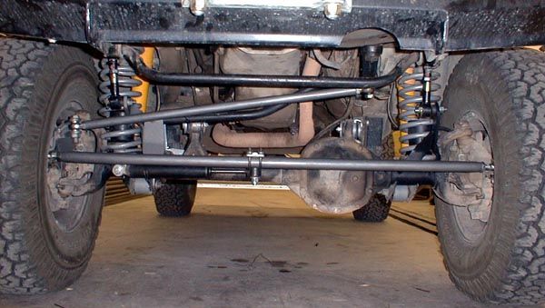 |
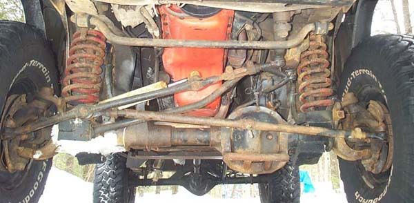
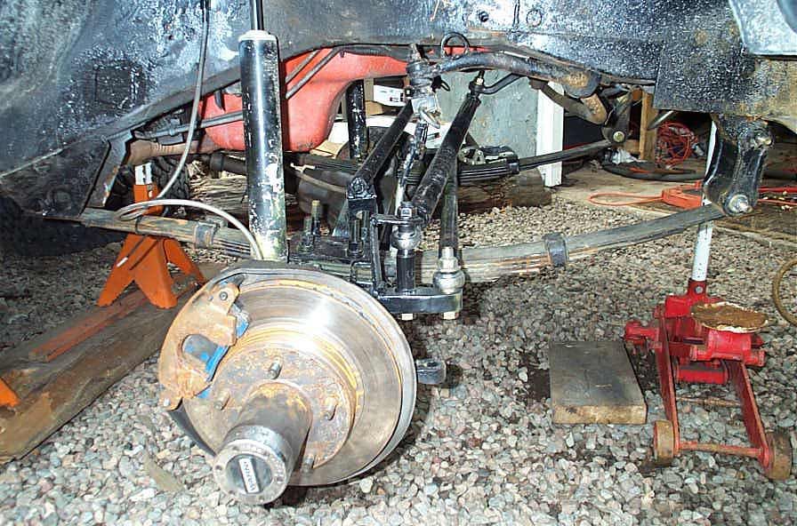
This is a crossover, but not Hy Steer setup. | ||||||||||||||||||||||||||||||||||||||||||||
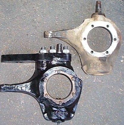
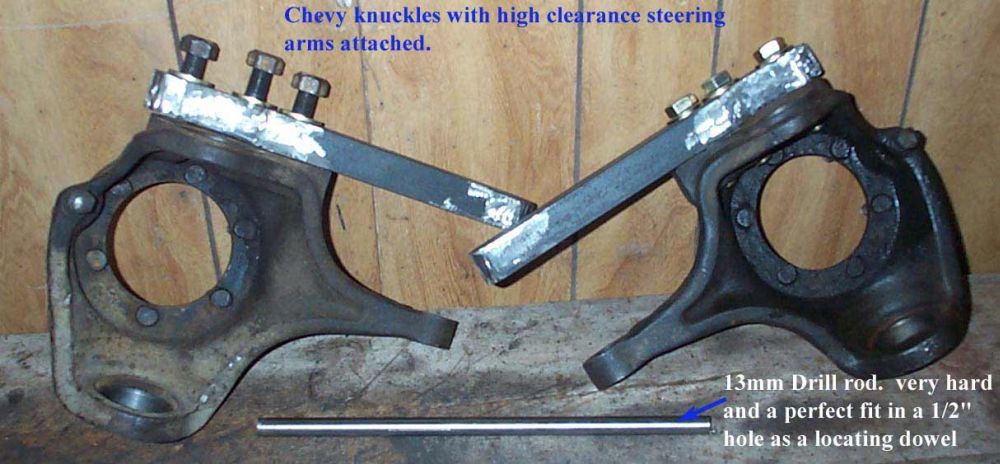
The first thing you need for a Hy Steer setup is a set of flat-top knuckles. Where do you find the Dana44 flat top knuckles?73-77 Chevy / GM 1/2 ton 4X4 with Dana44 passenger knuckles are flat tops. 73-87 Chevy / GM 1/2 ton 4X4 with Dana44driver's knuckle are flat tops. 74-77 Full Size Jeep (FSJ) (including Waggoneer, J series trucks, and narrowtrack Cherokee SJ) Driver and Passenger side. 69-77 early Ford Bronco Dana44 knuckles are different from the Gm and Jeep, but are machinable flat. Mid 70's Dodge's with Dana44 front axle (don't know details) The advantage to the GM driver's side knuckle is that it's already drilled and tapped. Some of these knuckles are flat and some have a peak in the center that is machinable. NOTE - as with all things truck, Jeep, and 4X4 - the years have to be taken with a grain of salt. I have heard of 77's that are flat top, and 76's that are not - the pictures provided below will help you check. OK - so which Dana44 front axles DON'T have flat top knuckles?78 and later FSJ 78 and later GM passenger side 78 and later Ford F150 / Bronco Scout II Dana 44. How do I tell the difference by looking? |
|||||||||||||||||||||||||||||||||||||||||||||
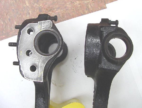 |
Flat top
knuckle on the left.
Non flat top knuckle on the right |
||||||||||||||||||||||||||||||||||||||||||||
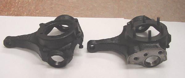 |
Non flat
top knuckle on the left
Flat top knuckle on the right. |
||||||||||||||||||||||||||||||||||||||||||||
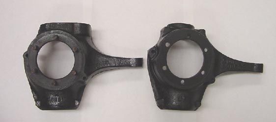 |
Flat top
knuckle on the left.
Non flat top knuckle on the right |
||||||||||||||||||||||||||||||||||||||||||||
 |
This is an early Bronco D44 flat top knuckle | ||||||||||||||||||||||||||||||||||||||||||||
 |
Non flat top knuckle, upper right. Flat top knuckle with steering arm attached, lower left. |
||||||||||||||||||||||||||||||||||||||||||||
What parts do I need to run a flat top knuckle Dana44 with a 5x5.5" bolt pattern?Essentially you run the Chevy or FSJ knuckle out, but you use a '76-'92 Ford F-150 Hub, rotor, and Inner Wheel bearing seal. (Except the '87-early '88 model Fords with the weird flange mount hub). The manual lockout is the same part for both. Timken Bearing Numbers76 Chevy / 85 F-150 inner wheel bearing: Set 37 76 Chevy / 85 F-150 outer wheel bearing: Set 45 76 Chevy / 85 F-150 Front Axle Spindle Outer oil seal 722109 76 Chevy / 85 F-150 Front Axle Spindle Inner oil seal 722108 76 Chevy / 85 F-150 Spindle bearing B2110 Inner wheel bearing seal (fits in back of hub) Chevy 24898 Ford 24917 Warn premium locking hub applications that workPart # 20990 Locking hub applications that work:Chevrolet/GMCBlazer, Jimmy, Suburban '69-91 1/2 Ton Pickup '69-87 3/4 Ton Pickup '77-87 DODGE1/2 Ton Pickup & Ramcharger '69-74 1/2, 3/4 Ton Pickup & Ramcharger '80-93 FORDBronco '66-96 1/2 Ton Pickup '59-96 3/4 Ton Pickup '59-75 3/4 Ton Pickup, Light Duty '77.5-97 JEEPFull Size Wagoneer, Cherokee, J-10 Pickup, Commander '74-91 J-20 Pickup '77-87 F150 hub and rotor part #s
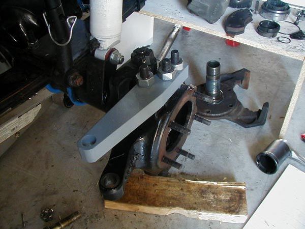
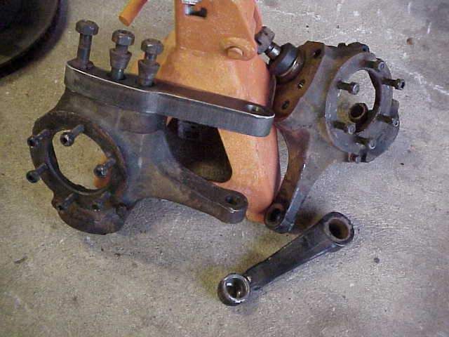
Great, so I've got the knuckles what next?The heart of a Hy Steer system is the steering arms, these are the custom pieces that are attached to the top of the flat top knuckles, and to which the steering linkage (drag link and tie rod) are attached. They are available from many sources (see links at the bottom of the page), or can be custom made if you have the tools and skill. When making or buying, things to consider are:
Here are some pics of some arms to give you an idea of what's available: |
|||||||||||||||||||||||||||||||||||||||||||||
 |
Arms from Extreme Gear Offroad. | ||||||||||||||||||||||||||||||||||||||||||||
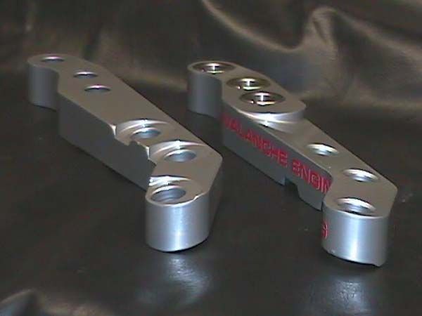 |
Avalanche's new arms. | ||||||||||||||||||||||||||||||||||||||||||||
 |
Avalanche arm mounted. | ||||||||||||||||||||||||||||||||||||||||||||
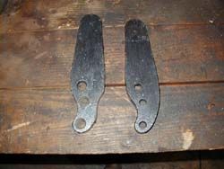 |
Basic undrilled arms. | ||||||||||||||||||||||||||||||||||||||||||||
 |
Arms and mounting hardware from Tri County Gear. | ||||||||||||||||||||||||||||||||||||||||||||
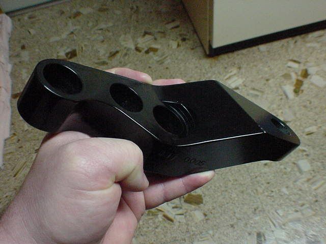 |
Super trick step-up billet arms from OTT Industries. | ||||||||||||||||||||||||||||||||||||||||||||
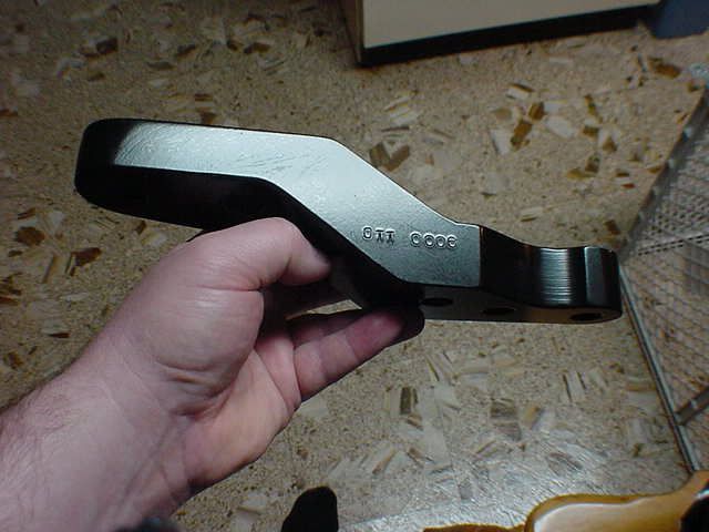 |
Super trick step-up billet arms from OTT Industries. | ||||||||||||||||||||||||||||||||||||||||||||
 |
A homemade arm attached with tapered lug nuts by Steve Meyers. | ||||||||||||||||||||||||||||||||||||||||||||
 |
Basic Arms from BR Fabworks (Bob Roggy). | ||||||||||||||||||||||||||||||||||||||||||||
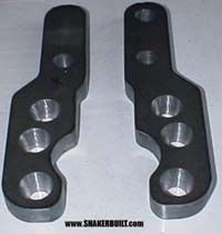 |
Nice "step in" arms from Shakerbuilt with good clearance from the tire built in. | ||||||||||||||||||||||||||||||||||||||||||||
 |
Cool "step-up" arms from BR Fabworks. | ||||||||||||||||||||||||||||||||||||||||||||
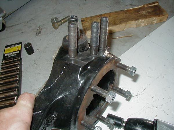
Alright - but what's all the fuss about how you attach the arms to the knuckle - why can't I just bolt them on?I'll let the text below explain, comments from knowledgeable folks (well, for the most part - some of the comments are mine ! :-)
The steering arm obviously experiences continued cyclical loads that place the mounting devices (bolts or studs) in shear load. ( I realize the strength of the joint is primarily achieved by the friction between the mating surfaces - none-the-less the fasteners still experience these loads - as evidenced by them loosening) SAE bolts are not designed to be loaded in shear, not to mention are not manufactured to close enough specs to allow a tight enough fit so that play will not develop and they will not begin to oval out the hole. Not to mention, drilling holes is not the proper way to achieve an exact dimension hole - it should be rough drilled and then reamed to final size. So if bolts are used, holes should be reamed, and proper shear bolts (like AN - can't quote a number off the top of my head) should be used. This is expensive and rare and more difficult, so GM came up with the ingenious solution of using a stud with a split cone washer, so that as the nut tightens, the cone cinches down and provides the required zero clearance fit while still allowing use of SAE grade/spec hardware. You can use bolts, but you have to use the right kind, or do something else to compensate (like using interference fit locating dowels). |
|||||||||||||||||||||||||||||||||||||||||||||
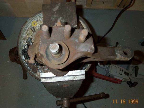 |
Here are the stock studs in a GM knuckle. | ||||||||||||||||||||||||||||||||||||||||||||
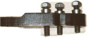 |
This
shows the studs, cone washers, and locking nuts.
And here are the studs and cone washers part numbers. GM calls the cone washers "adapters". Stud Adapter (cone washer) Each of these were about $3.50 a piece. So it cost me under $24 for the studs and washers per side. And GM does not sell the nuts (or at least my local dealer said they were not available). It is a 9/16-18 that's needed. TriCounty Gear also sells the hardware separately. $20 for the 3 9/16-NF studs, 3 conical "washers" and the 3 9/16 aircraft "stover" nuts. |
||||||||||||||||||||||||||||||||||||||||||||
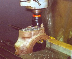 |
Knuckle being machined flat. | ||||||||||||||||||||||||||||||||||||||||||||
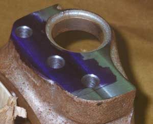 |
Knuckle machined flat and drilled. | ||||||||||||||||||||||||||||||||||||||||||||
OK - you've got the knuckles and the arms all sorted out - time to build / buy the linkage.Since you've come this far, it only makes sense to me to do a "true" Hy Steer setup and mount the draglink and the tie rod above the springs. You basically have 2 choices 1) A crossover design, where draglink and tie rod are independent. The advantage being that toe and steering wheel center are easily adjusted independently without having to disconnect anything, and that there is no chance of the draglink "rolling" the tie rod before steering the wheels. the disadvantage being the crowded linkage mounting on the passenger side steering arm, and the possibility for bind between tie rod and draglink. 2) An inverted T setup, where draglink mounts to tie rod. The advantage being simpler mounting on passenger side steering arm, and potentially less bind. The disadvantage being the draglink has to be detached from the tie rod in order to adjust toe. In either case, exactly how you lay out the linkage will depend on things like spring height, location of steering box, type of steering arm used etc. You can read about my crossover steering and the parts I used in parts 2 - 5 later in this article. A very popular Inverted T setup is to use '85 Chevy Blazer steering joints and custom tubes. The part numbers required are: Tie Rod: Drag Link: The ES2027L and ES2026R are stock 85 Blazer drag link ends. The ES2233L and ES2234R are stock 85 Blazer tre's. the ES2233L is the tie rod end (not on the drag link) that has the steering stabilizer hole that is re-tapered to the GM spec (1.5"/ft, but Drag link end has same taper, but larger hole). And all of these are 7/8-18" on the threaded ends GM P/N's for the jam nuts (discontinued) 14024806 Below are some pics of this setup from Steve Meyers excellent page. His article is linked below. |
|||||||||||||||||||||||||||||||||||||||||||||
 |
ES2027L at Pitman arm. Photo: Steve Meyers |
||||||||||||||||||||||||||||||||||||||||||||
 |
ES2233L mounted to steering arm, with stock steering stabilizer hole re-tapered so that ES2234R on end of draglink will fit to it. Photo: Steve Meyers |
||||||||||||||||||||||||||||||||||||||||||||
 |
ES2234R of tie rod attached to drivers side steering arm. Photo: Steve Meyers |
||||||||||||||||||||||||||||||||||||||||||||
 |
Top pic
is ES2233 which has a stock hole for steering stabilizer. This hole
has to be drilled and re-tapered from the other side for the TRE on the
draglink.
Bottom pic is of an ES2010 Photo: Steve Meyers |
||||||||||||||||||||||||||||||||||||||||||||
 |
H8Mondays has a unique and trick setup. he made his tie rod from solid chromoly stock, and had an area on the rod machined flat, drilled, and tapered to accept the end of his draglink. I really like this setup for the clearance and no bind it gives between draglink and tie rod. Very cool! |
||||||||||||||||||||||||||||||||||||||||||||
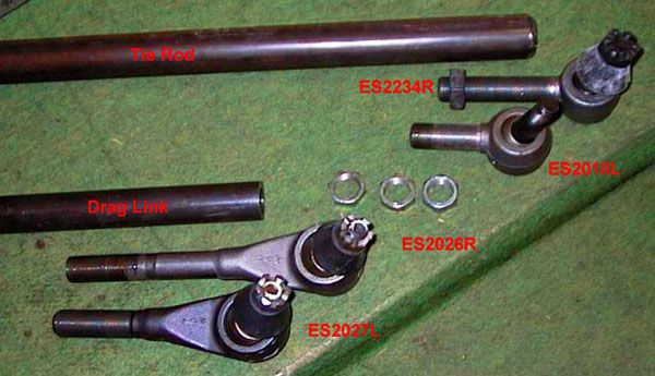 |
Some more TRE part numbers and pics for your info. | ||||||||||||||||||||||||||||||||||||||||||||
Part 2 - Design #1Dana 44 Hy Clearance crossover steering Ver. 1 After building my Hybrid front axle with D44 outers, including flat-top knuckles, it was time to design the steering. This was my first attempt at the "Hy Steer crossover steering" setup on my Jeep. In the end, some parts worked, some needed redesign. I eventually went through 3 more setups before being satisfied. I have included all 4 setups so as to show what I learned along the way. This is the first setup, the next 3 are linked at the bottom of the page. Each successive page just shows the parts that were redesigned, so all 4 contain useful info. |
|||||||||||||||||||||||||||||||||||||||||||||
 |
One of the first decisions is whether to use rod ends (Heim joints) or TRE's (standard automotive tie rod ends). I chose rod ends because they are reasonably cheap, even for very good quality, available in many different size bearings with 3/4-16 threaded shanks (the weld in threaded bungs for the ends of the tubing are only available up to 3/4-16), and since they do not require a tapered mounting hole, it is far easier and cheaper to R&D different setups with rod ends. | ||||||||||||||||||||||||||||||||||||||||||||
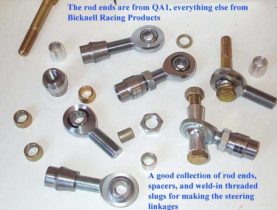 |
The Rod
Ends I chose are from QA1, | 21730 Hanover Avenue | Lakeville, Minnesota
55044 | Toll-Free: 800.721.7761.
I ordered them direct from the manufacturer.
All the other hardware is from the Bicknell Racing Products catologue, ordered from my local race car supplier, R&D Performance center, RR#5, Truro, N.S. 1-800-565-3795. |
||||||||||||||||||||||||||||||||||||||||||||
These are the reasons I chose to use weld in threaded slugs (or bungs) instead of just buying the correct ID tube and having it tapped: Using the threaded slugs might give you superior
threads than having the local shop cut the threads in the end of the
tubing, particularly if the The rod ends and radius slugs I use are designed to work together. However, Im probably overcomplicating the thread form concern (as usual) and theyre all probably some sort of SAE standard, so this is likely not a big concern (other than the previously mentioned bit about SAE not allowing cut threads I guess in the past some SAE bolts used to have cut, rather than rolled threads, and they were not as good.) One more thought about slugs vs. tapping tube. Obviously tapping the tube you are limited to the alloy the tube is made from, and I'm not sure your standard low carbon 1020 DOM mild steel is the best thing for thread forms. On the other hand, the slugs can be made from an alloy better suited to thread forms, as long as it is weldable to the tube. |
|||||||||||||||||||||||||||||||||||||||||||||
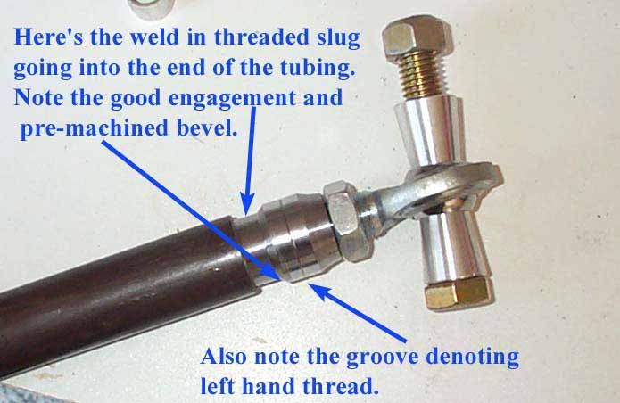 |
Essentially they are a tight slip in fit inside the tube about an inch, and the edge is beveled for the weld. | ||||||||||||||||||||||||||||||||||||||||||||
 |
Also, note the "radius" after the main body and before the end, where the jam nut is. In terms of flow of stress and therefore fatigue life, this is a superior feature over just having the threaded tube end abruptly at the point where the threaded shank of the TRE or rod end enters. The abrupt change in diameter causes a concentration of stress and forms a weak point at this area, as the stress flowing along the tube has to "bunch up and get around the sharp 90° corner" formed at the abrupt change in radius. That's why I keep calling them "radius" slugs. | ||||||||||||||||||||||||||||||||||||||||||||
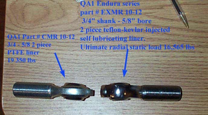 |
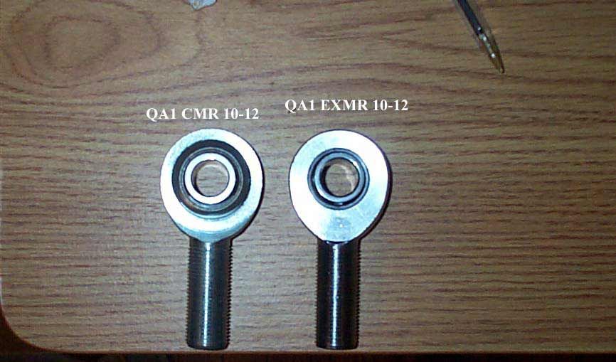
No matter
how much research you do before hand, sometimes you just need to handle
the parts. So I ordered 2 different styles of rod end from
QA1. Thes are them and their specs. I paid $16.29
for EXMR 10-12 and $12.14 for CMR 10-12.
The actual part numbers are: CMR10-12T - Right hand thread CML10-12T - Left hand thread EXMR10-12 - Right hand thread EXML10-12 - Left hand thread |
||||||||||||||||||||||||||||||||||||||||||||
 |
|||||||||||||||||||||||||||||||||||||||||||||
 |
After handling the, in my opinion, the EXMR are the superior part. And incidentally the same ones Rubicon Express use in their products. | ||||||||||||||||||||||||||||||||||||||||||||
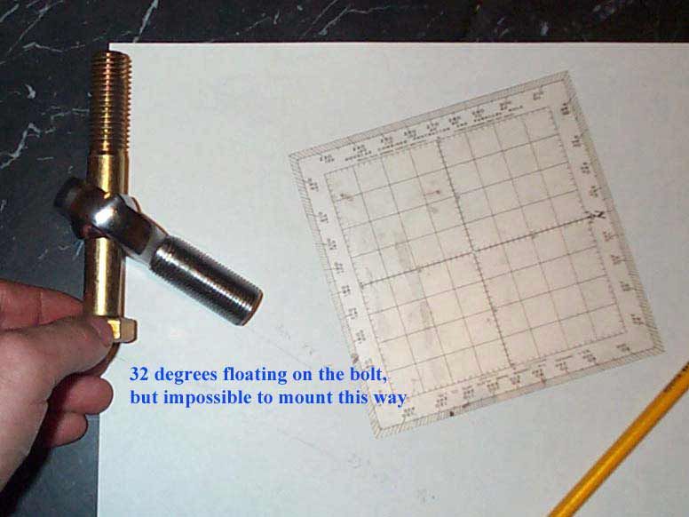 |
I have read many a good debate online about whether rod ends or TREs offered better "misalignment angle". Since I had already decided on TREs for the reasons stated, I decided to do some first hand testing. | ||||||||||||||||||||||||||||||||||||||||||||
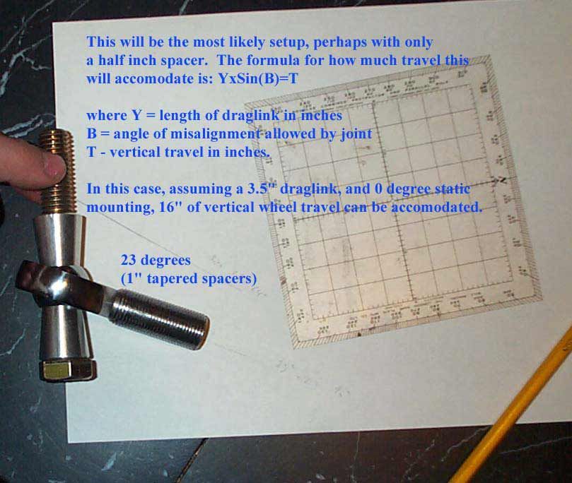 |
Slight typo on the pic label, it should read: "assuming a 3.5 FOOT draglink" | ||||||||||||||||||||||||||||||||||||||||||||
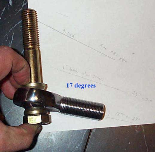 |
Misalignment of 17 degrees with the minimum 1/4" spacers. | ||||||||||||||||||||||||||||||||||||||||||||
 |
Here are the "on the Jeep" testing shots. | ||||||||||||||||||||||||||||||||||||||||||||
 |
|||||||||||||||||||||||||||||||||||||||||||||
 |
|||||||||||||||||||||||||||||||||||||||||||||
 |
|||||||||||||||||||||||||||||||||||||||||||||
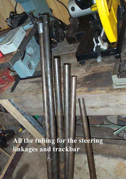 |
Here's the pile of tubing I ordered for the linkages. | ||||||||||||||||||||||||||||||||||||||||||||
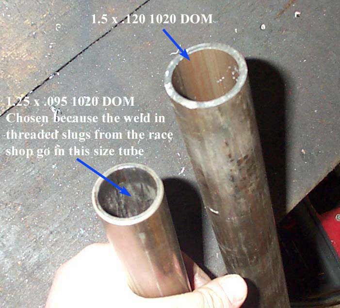 |
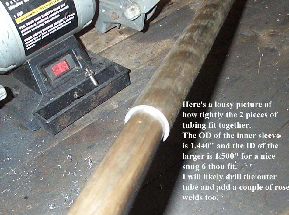
The weld in threaded slugs are made to fit in 1.25" x .095 wall tubing - light and strong for the race car builders. I wanted something a little beefier for trail use, so I ordered some 1.5" x .120 tube so sleeve over the other. That's a total of .215" thick - almost 1/4"!! | ||||||||||||||||||||||||||||||||||||||||||||
 |
|||||||||||||||||||||||||||||||||||||||||||||
 |
|||||||||||||||||||||||||||||||||||||||||||||
 |
There's a ton of info on the research page about D44 steering arms, who makes them, how, why, etc. These are my home-made arms. | ||||||||||||||||||||||||||||||||||||||||||||
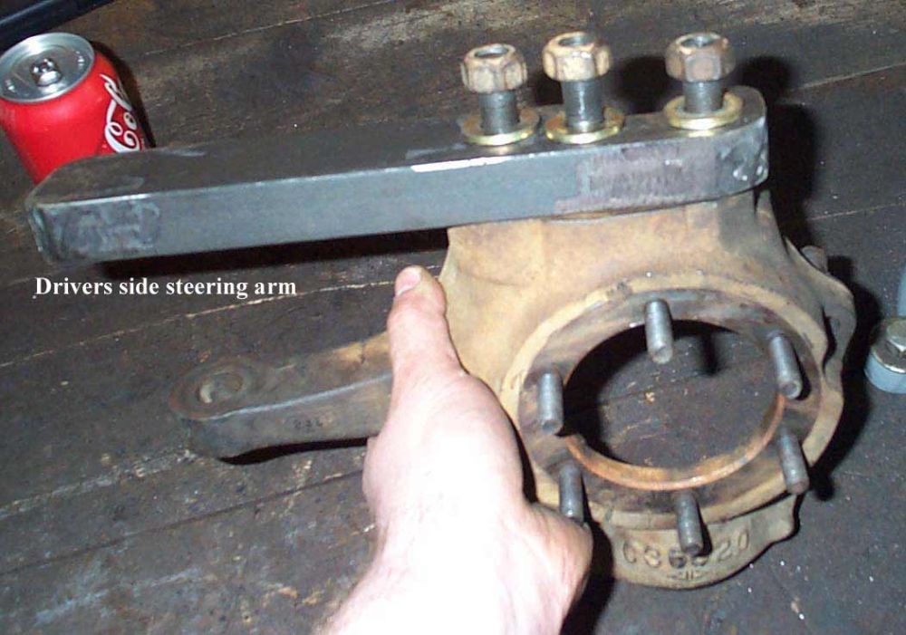 |
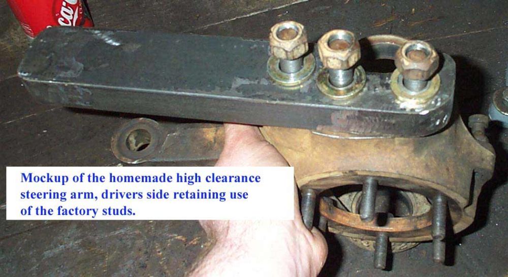
To make them I cut the shape from 1" thick steel. For the drivers side, I tacked the stock Chevy steering arm to the blank, and drilled the 3 holes. That was all that was required since the stock drivers side Chevy steering knuckle is already drilled and tapped. I retained the use of the 3 9/16 studs and added new hardened washers and ovalated locking nuts. | ||||||||||||||||||||||||||||||||||||||||||||
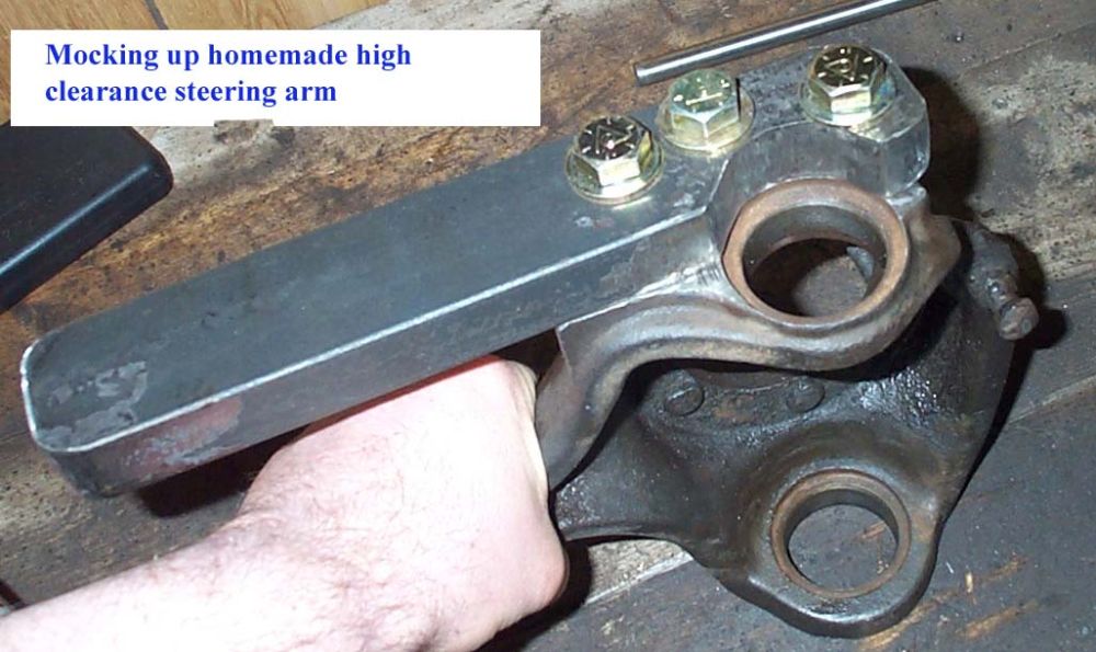 |
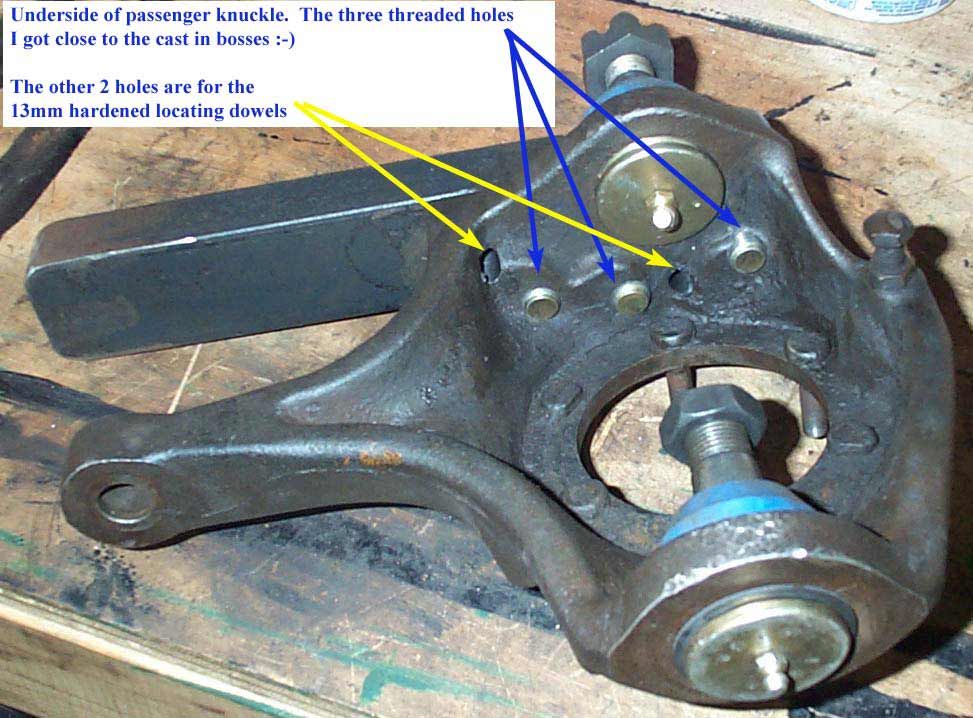
The passenger side was a bit more work. First the "flat" surface of the knuckle has to be machined flat. Then I tacked the arm on the knuckle, and drilled through both together with a 33/64 drill bit (the size required for tapping the knuckle). Then I knocked the arm off the knuckle, tapped the 3 holes in the knuckle with 9/16-NF tap, and drilled the holes in the arm out to 9/16" for the bolts. On this side I used Grade 8 SAE 9/16-NF bolts and hardened washers from Bowman. | ||||||||||||||||||||||||||||||||||||||||||||
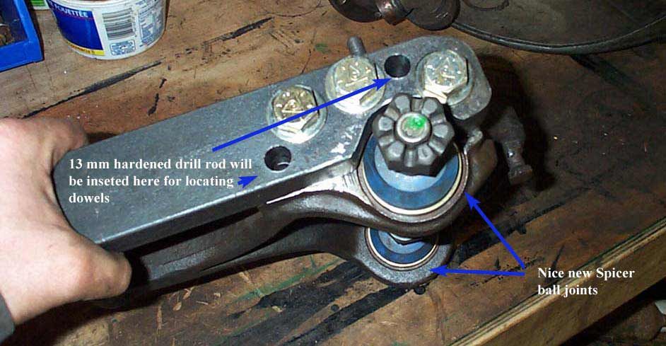 |
Because I was not re-using the stock Chevy tapered hole and split conical washer system for positive zero tolerance location of the steering arm (an excellent design, but requiring more expensive machining and the rob-you-blind Chevy hardware [see research page]), I needed another method for assuring a tight positive fit that won't loosen, develop play, and place dangerous shear loads on the bolts. The bolts alone are not sufficient since, in order to be able to fit the bolt in and out of the hole, there is too great a clearance between the OD of the bolt and the ID of the hole. remeber, the bolts are not for locating, just clamping. | ||||||||||||||||||||||||||||||||||||||||||||
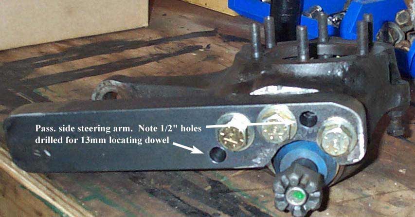 |
I decided on using locating dowels of hardened steel, pressed (pounded!) into slightly undersize holes for a tight fit. | ||||||||||||||||||||||||||||||||||||||||||||
 |
|||||||||||||||||||||||||||||||||||||||||||||
 |
|||||||||||||||||||||||||||||||||||||||||||||
| The next pics show how the linkage all went together, and some of the things I wasn't happy with. | |||||||||||||||||||||||||||||||||||||||||||||
 |
This is
the drivers side. The hole for the tie rod was drilled the same
distance from the center of the balljoint as the stock Chevy hole was. I
used 2 tapered 1/2" steel spacers on either sides of the rod end, and
a 5/8" Grade 8 bolt with oval locking nut.
It's not a good design since the bolt is too long, and really the rod end should only be mounted in double-shear, especially with spacers on either side. As it is, the bolt is not a precise fit in the arm (no SAE bolt and drilled hole assembly is - precision fit for an assembly such as this can only be accomplished by drilling the hole undersize and reaming to final size, then using an appropriate precision bolt like an AN spec bolt), and the rod end will place bending loads on the bolt, which will fatigue and / or begin to wear the hole, leading to looseness and more wear in a vicious cycle until something fails. A proper "double shear" assembly would have the arm forming a "bracket" on either side of the rod end. |
||||||||||||||||||||||||||||||||||||||||||||
 |
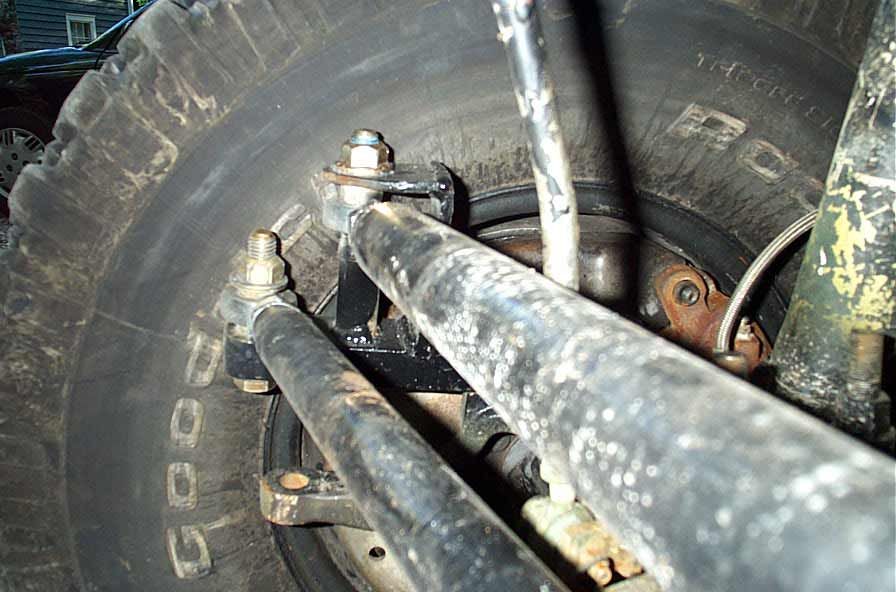
On the
drivers side, I used the same two 1/2" steel spacers for the tie rod,
and a 1.5" spacer underneath the drag link rod end and 1/2"
spacer on top. This was required to space the drag link up enough to
clear the tie rod (notice too that I could only build the tie rod out of
the single thinner tube, or it would have been too large and interfered
with the drag link).
The result is an ungodly mess of spacers and improperly loaded bolts and just plain sucks from an engineering standpoint. |
||||||||||||||||||||||||||||||||||||||||||||
 |
This is
almost too embarrassing to show, but hopefully you can learn from my
mistakes. I had to stack 2 spacers under the drag link to get the
1.5", one of which was aluminum and began to deform when the 5/8" bolt was torqued. Yeuch !!
The drag link hole in the steering arm was drilled the same distance from the center of the balljoint as the end of the pitman arm is from the steering box output shaft - namely 6" in my case. |
||||||||||||||||||||||||||||||||||||||||||||
 |
I had to bend the swaybar disconnect to clear the drag link, and the track bar axle mount used the old drivers upper control arm bracket on the axle. In the end, I removed the swaybar and trackbar altogether and do not regret it. | ||||||||||||||||||||||||||||||||||||||||||||
 |
Another
pretty gross setup. A 1" aluminum spacer on one side of the
pitman arm rod end, and a 1/2" steel on the other.
The automotive industry designed and uses TREs for a reason !! |
||||||||||||||||||||||||||||||||||||||||||||
 |
The frame side trackbar bracket was the only bit that was sort of OK, nut I ended up junking it anyway. | ||||||||||||||||||||||||||||||||||||||||||||
 |
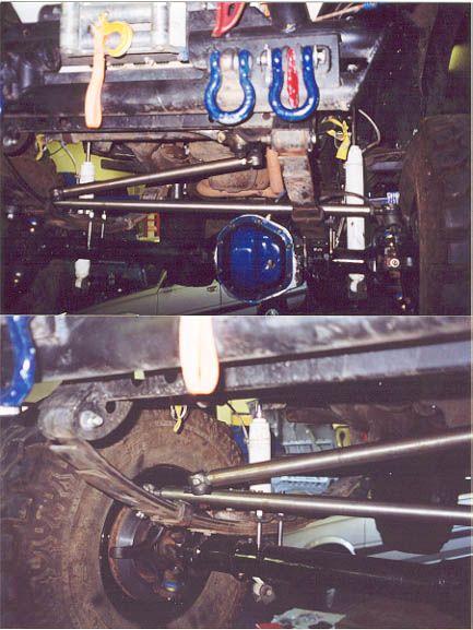
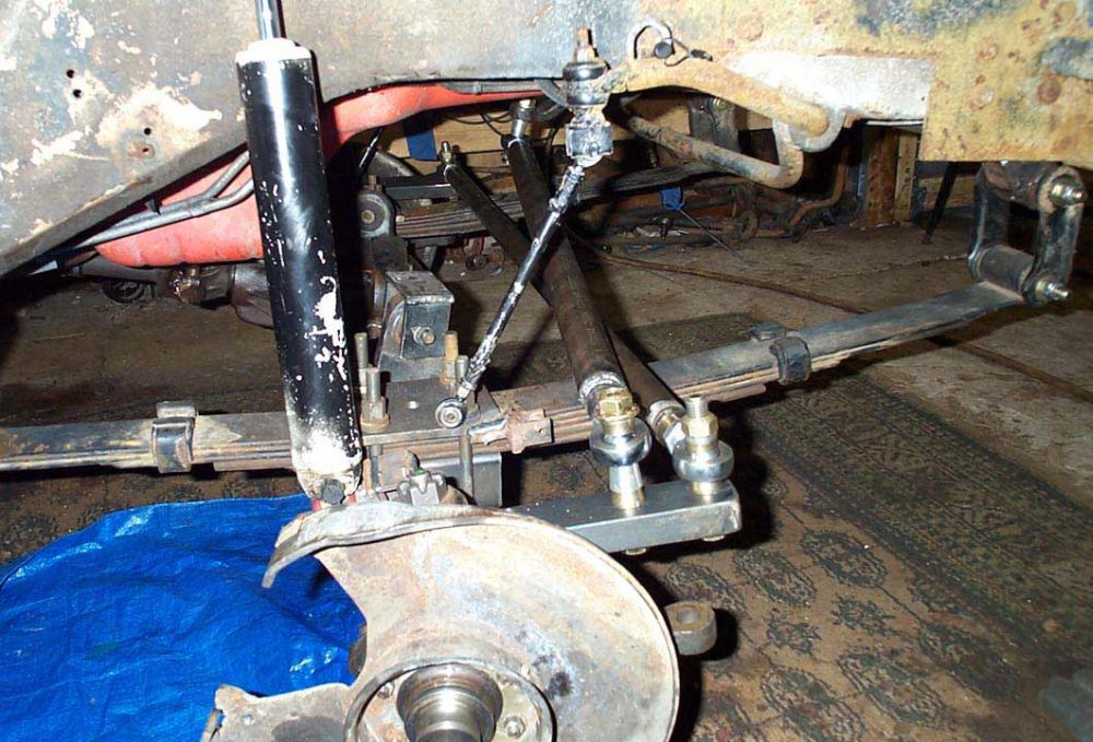
Looks good if you didn't know any better !! | ||||||||||||||||||||||||||||||||||||||||||||
 |
At least it was all up out of the way. | ||||||||||||||||||||||||||||||||||||||||||||
 |
Well, it was all tucked up nice and safe, so that was something. | ||||||||||||||||||||||||||||||||||||||||||||
 |
The problem was, even with the awful mess of spacers the drag link and tie rod still intefered | ||||||||||||||||||||||||||||||||||||||||||||
 |
This shows the problem | ||||||||||||||||||||||||||||||||||||||||||||
Part Numbers Used:
Summary: A good start, but definitely not the complete solution. The use of rod ends is not the best, and the draglink and tie rod bind with any suspension movement. On to Version 2. Part 3 - Design #2Version 1 didn't work perfectly so I made it worse. A lesson in what NOT to do!This was pretty much a disaster - it's sole purpose is now to serve as a warning to others. The main issue to be resolved was addressing the binding between the drag link and tie rod. I accomplished this by raising the draglink attachment at the knuckle, and reducing the spacers under the tie rod rod ends. Since I was still doing R&D, i kept the rod ends for now -no point reaming a bunch of tapered holes for TREs and then having to re do them. The nice thing about the rod ends was the ease of changing spacers and moving stuff around. It worked as far as eliminating contact between the linkages, but using that great big spacer under the drag link is not a good design, and even with the weenie little 1/4" extra bracket, this was not a proper "double shear" arrangement. I ran and wheeled this setup for a while, but just wasn't comfortable with it, so it went in the bin, and version 3 was born. Anyway - here's a look at the ill fated version 2. |
|||||||||||||||||||||||||||||||||||||||||||||
 |
Much better clearance between the linkages. | ||||||||||||||||||||||||||||||||||||||||||||
 |
Much better clearance between the linkages. | ||||||||||||||||||||||||||||||||||||||||||||
 |
But that drag link attachment is just ugly! | ||||||||||||||||||||||||||||||||||||||||||||
 |
It might work with proper bracing / brackets | ||||||||||||||||||||||||||||||||||||||||||||
 |
|||||||||||||||||||||||||||||||||||||||||||||
 |
The drag link was nice and flat for no bump steer | ||||||||||||||||||||||||||||||||||||||||||||
 |
|||||||||||||||||||||||||||||||||||||||||||||
 |
But that bolt is potentially under tremendous force. | ||||||||||||||||||||||||||||||||||||||||||||
 |
I didn't bend or break it, but that "warm fuzzy" feeling just wasn't there. | ||||||||||||||||||||||||||||||||||||||||||||
 |
|||||||||||||||||||||||||||||||||||||||||||||
 |
|||||||||||||||||||||||||||||||||||||||||||||
 |
With the tie rod sitting on 1/4" vice 1/2" spacers, it did get a little close to the springs. | ||||||||||||||||||||||||||||||||||||||||||||
 |
The clearance was ok, much improved | ||||||||||||||||||||||||||||||||||||||||||||
 |
|||||||||||||||||||||||||||||||||||||||||||||
 |
But still a little close with the right side drooping. | ||||||||||||||||||||||||||||||||||||||||||||
Summary: A learning experience......which led to the even more ill fated Version 3 !!! Part 4 - Design #3From bad to worse - see me bend and brake this poor design. More of what didn't work.Not happy with the setup of version 2, I tried something else. I attached the drag link to the steering arm with the rod ends and only a 1/2" spacer. I then moved the tie rod down to the stock location in the Chevy knuckles using TREs |
|||||||||||||||||||||||||||||||||||||||||||||
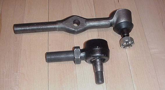
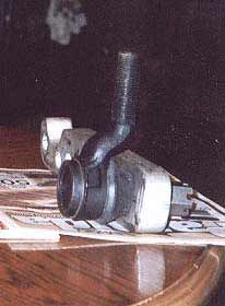 Photo courtesy Jeff Ayers |
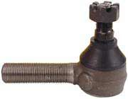
This is
the ES375 TRE that I used.
The is the only one choice for a 3/4-16 TRE is with the "big" taper, that is from .776"to .667" (same as the TRE taper in stock Chevy and FSJ Dana44 knuckles) The part numbers are: Moog ES375L - Right hand thread, drivers side "outer" tie rod end (left hand side) for '67-'72 1/2ton & 3/4ton GMC trucks Moog ES375R - Left hand thread, Passenger side "outer" tie rod end (left hand side) for '67-'72 1/2ton & 3/4ton GMC trucks The catch with these is that they have a "dog leg" in them, that can either really help or really hurt your design, depending on application. This helped me as it helped the tie rod clear the underside of the springs. There is no "straight" TRE with 3/4-16 threads and the "big" taper. |
||||||||||||||||||||||||||||||||||||||||||||
 |
As you can see, the tie rod is left much more vulnerable down here, and I bashed the daylights out of it in just one trip. So much for driving finesse! | ||||||||||||||||||||||||||||||||||||||||||||
 |
Nice bend ! | ||||||||||||||||||||||||||||||||||||||||||||
 |
The final
really bad idea of version 3 was to make the tie rod double wall ( 1.25" x .095 wall tubing sleeved with 1.5" x .120 tube ).
That's a total of .215" thick - almost 1/4"!!
This was TOO strong, as the first time I bashed it the $80 TRE snapped cleanly right where the threaded shank entered the rod (arrow). I was extremely lucky in that there were 3 threads left on the stub of a TRE and after painstakingly dressing them with a small file, I got the stub threaded back in enough to limp off the trail. |
||||||||||||||||||||||||||||||||||||||||||||
Summary: Back to the drawing board !!! On to version 4 Part 5 - Design #4:See me figure it all out, actually build something that works and return to using good old fashioned Tie Rod EndsOK - not happy with the rod ends of version 1 and 2, version 1 design caused binding, version 2 placed too much stress on the knuckle mount of the draglink, version 3 placed the tie rod in a vulnerable location - resulting in bending or TRE breakage. Time to put it all together in a system that will work. The major changes were the use of TREs at all 4 mounting points, and the use of a 2" spacer block of cold rolled steel placed between the knuckle and the steering arm. Due to the fact that the weld in radius slugs I used on my linkages have a 3/4-16 female thread, my choice of TREs was somewhat limited. There are only 2 TRE's available with 3/4-16 threaded shanks. They are 1) Moog ES-150L left hand thread and Moog ES-150R right hand thread These have the "medium" size taper that is from .714" to .636" The stock application include: FORD TRUCK F100/F250 61-65 They will be listed as "inner" and "outer" tie rod ends, with the inner being the left/drivers side (left hand thread, PN ES150L) and the outer being right/passenger side (right hand thread, PN ES150R) They are also available from: http://www.afcoracing.com/ and http://www.stockcarproducts.com/ 2) The other choice for a 3/4-16 TRE is with the "big" taper, that is from .776"to .667" (same as the TRE taper in stock Chevy and FSJ Dana44 knuckles) The part numbers are: Moog ES375L - left hand thread, drivers side "outer" tie rod end (left hand side) for '67-'72 1/2ton & 3/4ton GMC trucks Moog ES375R - right hand thread, Passenger side "outer" tie rod end (left hand side) for '67-'72 1/2ton & 3/4ton GMC trucks The catch with these is that they have a "dog leg" in them, that an either really help or really hurt your design, depending on application. There is no "straight" TRE with 3/4-16 threads and the "big" taper. |
|||||||||||||||||||||||||||||||||||||||||||||
 |
This is the Moog ES150. | ||||||||||||||||||||||||||||||||||||||||||||
Photo courtesy Jeff Ayers |
This is the Moog ES375. | ||||||||||||||||||||||||||||||||||||||||||||
 |
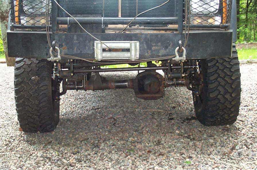
The "trick" that made the setup work for me was mounting the draglink to the top of the steering arm with an ES150 TRE, and mounting the tie rod underneath the steering arm using an ES375 TRE. The 2" spacer under the steering arm and the dog leg in the ES 375 allowed the tie rod to clear the springs, even mounted under the arm. | ||||||||||||||||||||||||||||||||||||||||||||
 |
Chad and
I bought a Tapered reamer for $200 Cdn from www.afcoracing.com
This expensive but cool tool allowed me to taper the original 5/8" straight holes drilled for the rod ends to be tapered for both the ES150 and ES375 Tie Rod Ends. The tie rod attachment points remain vertically above the stock Chevy knuckle locations. The draglink attaches to the steering arm 5.75" from the balljoint center. I moved it back 1/4" from the original 6" location to ensure no clearance issues between the linkages. |
||||||||||||||||||||||||||||||||||||||||||||
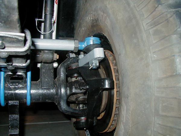
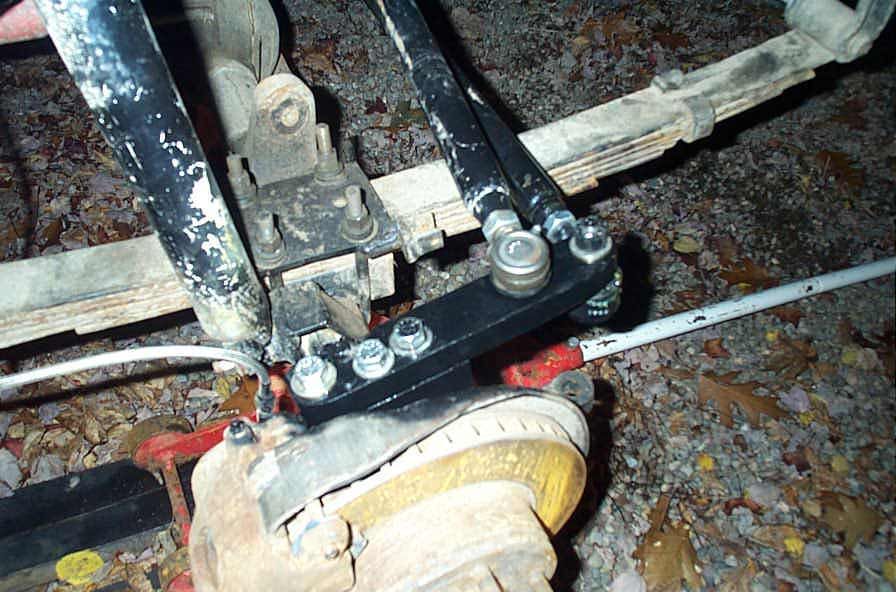
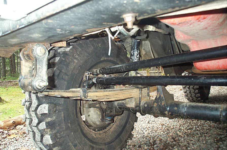
 |
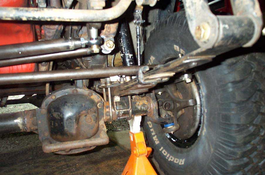
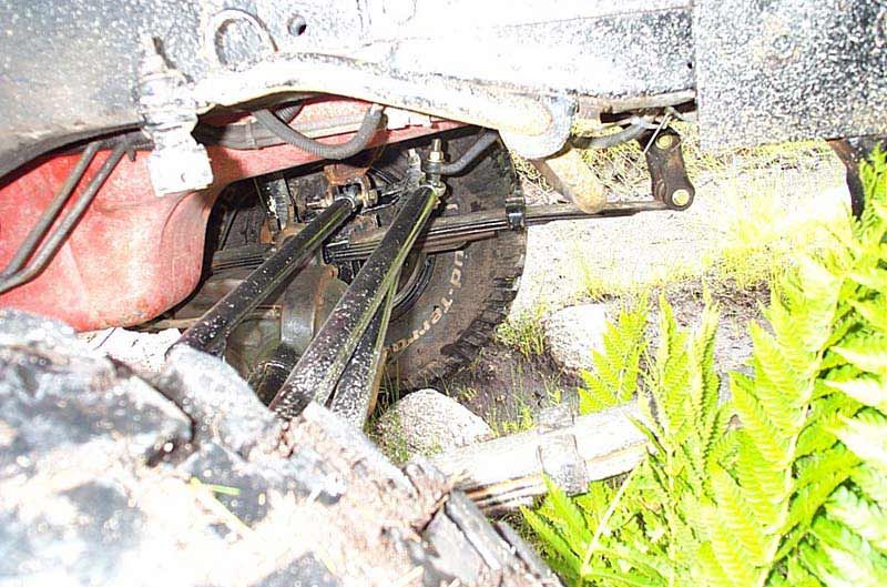
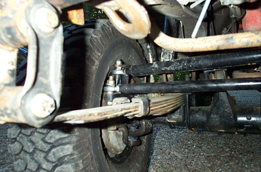
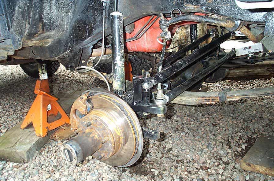
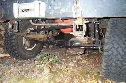
Drivers side, tie rod mounted under the steering arm with Moog ES375L. | ||||||||||||||||||||||||||||||||||||||||||||
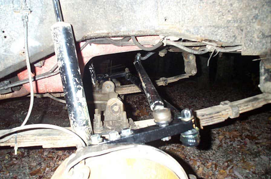
 |
In this pic you can see the drag link mounted to the (stock) pitman arm with a Moog ES150L. | ||||||||||||||||||||||||||||||||||||||||||||
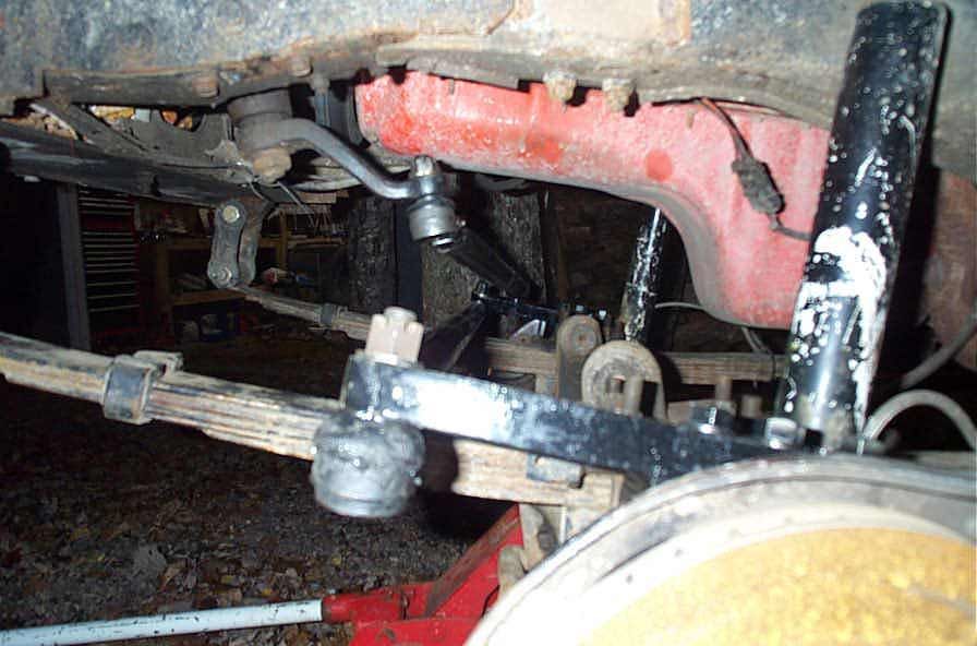
 |
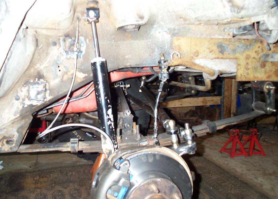
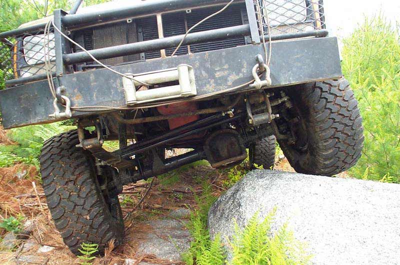
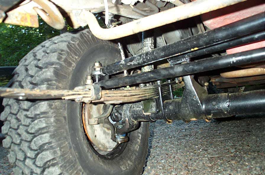
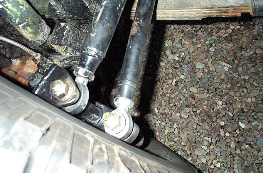
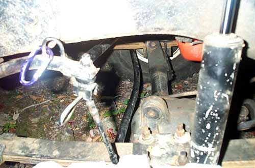
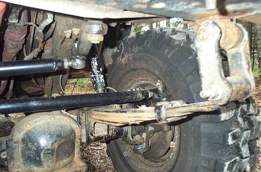
There is plenty of clearance between the tie rod and springs. | ||||||||||||||||||||||||||||||||||||||||||||
 |
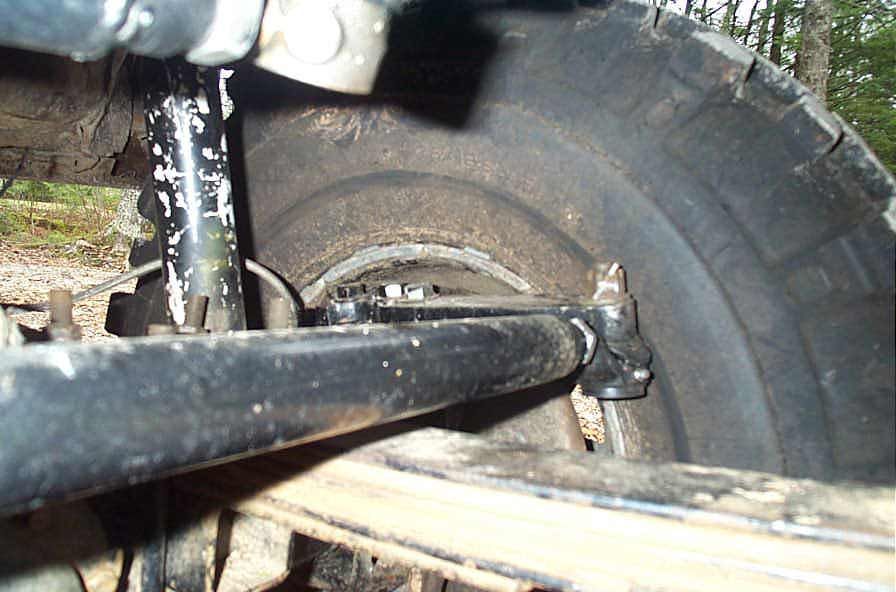
Up and out of the way again, perfect for my driving style :-) | ||||||||||||||||||||||||||||||||||||||||||||
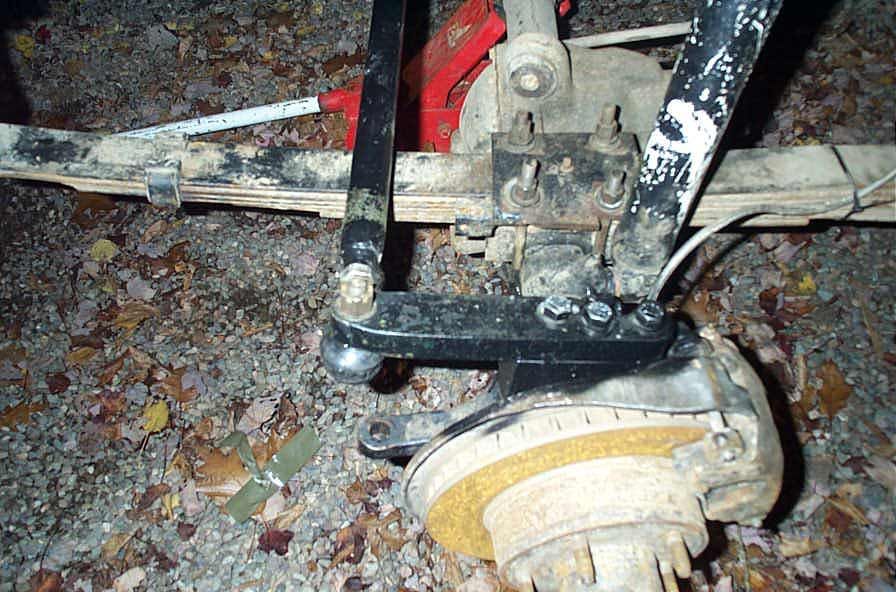
 |
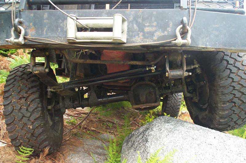
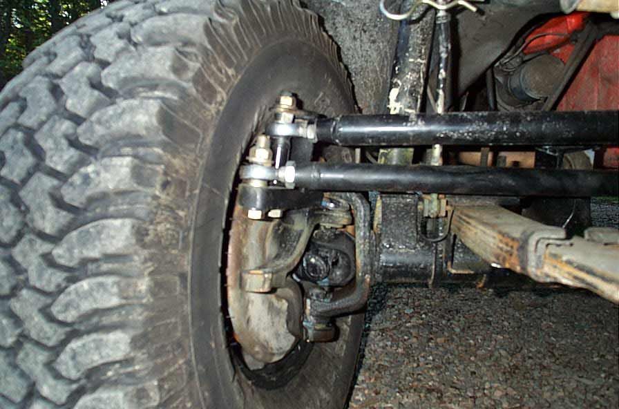
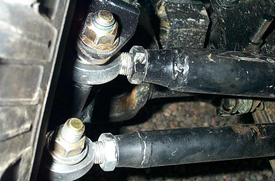
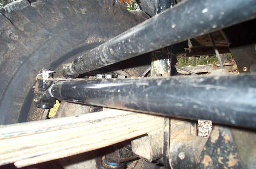
There is also plenty of clearance between the drag link and the tie rod, no more linkage bind. | ||||||||||||||||||||||||||||||||||||||||||||
 |
|||||||||||||||||||||||||||||||||||||||||||||
 |
|||||||||||||||||||||||||||||||||||||||||||||
 |
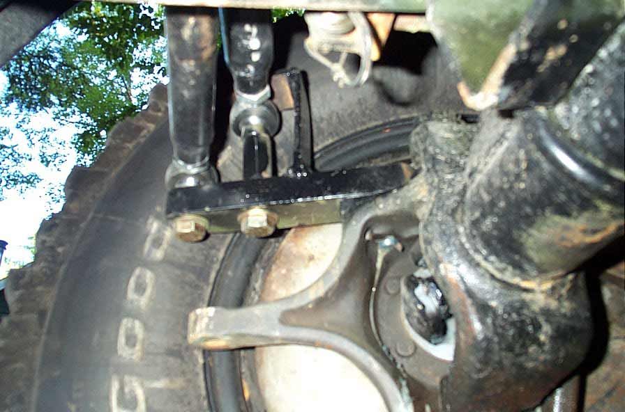
The 2" spacer, however, raises the steering arm to the point where is just rubs on the tire. No worries - custom beadlock wheels with less backspacing are on the way !! | ||||||||||||||||||||||||||||||||||||||||||||
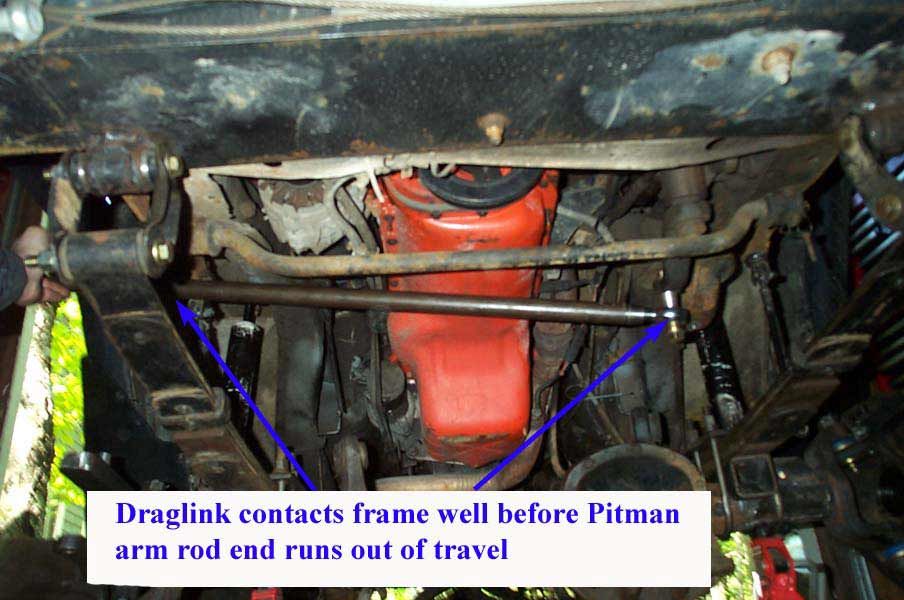
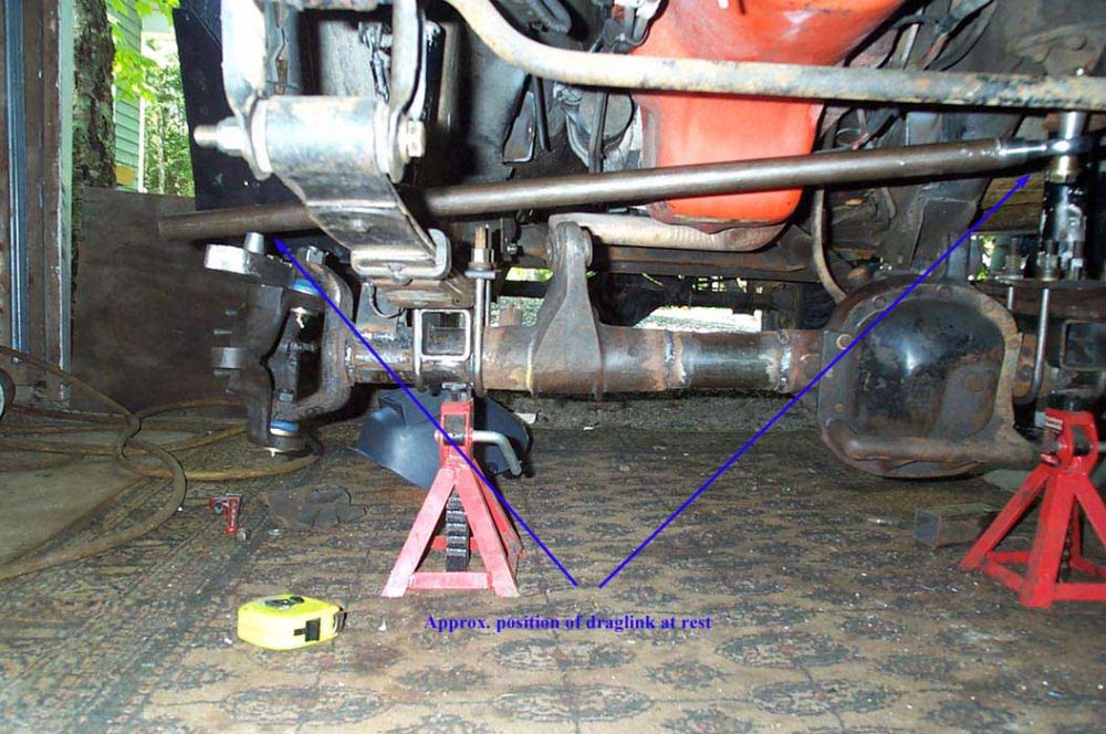
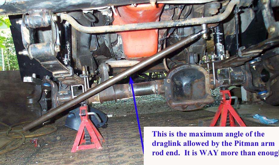
|
The 2" spacer also raises the draglink attachment enough for really nice angles on the draglink, resulting in no bumpsteer and plenty of allowable droop. | ||||||||||||||||||||||||||||||||||||||||||||
| Summary: Well, I think I have it now! In retrospect, if I were to start all over again. I would probably use an inverted T setup using '85 Chevy Blazer parts, where the drag link connects to the tie rod. Only trick would be either tapping the right size tube for the 7/8-18 threaded shanks of the Blazer TREs, or having the machine shop drill out and re-taper the weld in radius slugs (only issue is - try finding a local machine shop with a 7/8-18 Left hand tap, and even worse finding jam nuts in 7/8-18 (if they don't come with your TREs) is virtually impossible, and they too have to be custom made. See the RESEARCH page for details on this kind of setup. Right now, I'm very happy with my setup. | |||||||||||||||||||||||||||||||||||||||||||||
|