 |
The Cooling Bible By Bill "BillaVista" Ansell |
IntroductionThe cooling system – deceptively simple yet devilishly complicated. Like many things – your rig’s cooling systems is one of those things that seems simple, that most people think they understand, but which, behind the scenes, is actually a lot of fairly complicated stuff working together in a fine balance. Or not working together well – which is often the problem. |
|
In reality, “under the hood”, cooling systems contain a lot of pretty sophisticated engineering – laws of thermodynamics, pressure, turbulent and boundary-layer flow, aerodynamics, etc. As a result, because cooling seems simple, even though it isn’t, a LOT of misinformation and tenacious long-lasting myths exist surrounding it. So, let me get this out there – designing a complete cooling system is no easy task – especially if it’s for a high-performance rig that’s run hard. It takes a lot of know-how. So what are you to do? Well, the easy and obvious answer is to enlist the help of true professionals, like Griffin Thermal Products. You call them up, explain what kind of vehicle you have and what you want to do with it, and they will design, build, and supply what you need. These guys really know their stuff – they do everything from OEM, racing, off-road, & high performance, to industrial, locomotives, and aircraft. So if you have the means, and you just want results – skip to the end of this article, ogle the pretty pictures, then simply call them up and order your own. But – you don’t necessarily have to engineer your system to build something that works. As much as there is rumour and myth – there are also many tried and true approaches, many well-tested components, and many rules of thumb that DO work. The trick is – telling them apart. So, for those interested in a little more technical detail than just whom to call, that’s what this article will attempt to do – sort the myth from the truth and present some solid tech to help you down the road of putting your own high-performance cooling system together. At the very least, it will help you have a more productive and meaningful conversation with the experts at Griffin when you do call them to order what you need. Contents
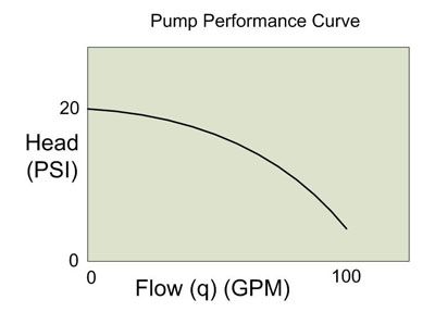
Physics and ChemistryIn this article I'm going to forgo too much detail in terms of physics, equations, and laws of thermodynamics - they get pretty complicated pretty quickly and will bog most of us down. Having said that, there are a few basic "laws" we should just remind ourselves of - because they crop up time and again and keeping them in mind will help keep us from making mistakes or falling prey to those ever-present myths that surround cooling systems. 1) Metal, engine components, fluids and gasses all expand when heated. 2) Heat rises - hot fluid will rise in a system and cooler fluid will descend. 3) Air or vapour is lighter (less dense) than liquid and will rise to the top of any closed system. 4) Liquids are incompressible. 5) Substances can change state between liquid and gas (vapour). Boiling water (a liquid) turning into steam (gas) is an example of this. When exactly this change of state occurs, depends on the temperature and pressure of the liquid. The greater the pressure a liquid is under, the higher the temperature it boils at (turns from liquid to vapour). 6) Heat spontaneously transfers from hotter objects to cooler objects. The rate at which this transfer occurs depends primarily on the difference in temperature between the two (the delta-T). When the difference is great, the transfer occurs extremely rapidly. As the temperature difference decreases - the rate of heat transfer decreases exponentially. This fact is an expression of Newton's Law of Cooling and understanding it is critical to dispelling one of the greatest and most-often quoted myths surrounding cooling systems. A good example of this law can be seen when quenching a red-hot piece of steel in a bucket of water. At first, the temperature difference (delta-T) between the red-hot steel and the water is huge - therefore the initial heat transfer occurs at a great rate - the steel initially cools very fast - almost instantaneously. However, after this initial cooling, the delta-T is much smaller, so the remaining cooling occurs much more slowly. If you removed the steel after a second or two - it has cooled a lot - but it will still be warm. To continue cooling the steel to the temp. of the water, you have to leave it in there quite a bit longer - because as it cools - the rate of cooling continually decreases as well. In short - initial cooling is fast, but subsequent cooling occurs more and more slowly until cooling that last little bit takes a long, long time. Remember this - we'll come back to it. Cooling System BasicsA vehicle's cooling system is designed to do one thing - maintain the engine at the proper operating temperature. Note that I didn't say the purpose is just to "cool the engine". This is one of the first and most often overlooked aspects of a cooling system (which isn't helped by the name). Yes, it's possible to "overcool" an engine, and doing so can be almost as damaging as allowing it to overheat. This is because all engines are designed to operate most effectively and reliably at a certain temperature. This normal operating temperature takes into account internal clearances, oil viscosity (which varies with temperature), and combustion efficiency (which affects power, economy, and emissions). Too hot, and critical clearances are lost, oil breaks down, pre-ignition occurs, metal composition is changed, parts start to weld together and severe damage occurs. Too cold and combustion is incomplete, power production is reduced, emissions are excessive, economy suffers, and oil never reaches the proper temperature and therefore viscosity and is therefore too thick to provide proper lubrication - especially between critical surfaces like main and rod bearings. To be fair - the majority of the work the cooling system must perform is to remove from the engine heat produced by combustion - but a good cooling system must also be designed to allow the engine to come up to proper operating temperature as quickly as possible and then keep it there. Power makes heat. The more power the engine creates, the more heat it creates. As wonderful as they are - spark-ignition internal combustion engines are actually pretty damn inefficient beasts. A typical engine will loose more than 30% of the power it produces to heat production. That's a LOT of heat! Peak combustion chamber surface temperatures can exceed 500°F and the temperature of the combustion itself can exceed 3000°F. In fact, if you were to run an engine without a cooling system, even for only a short time, the temperatures produced could quickly melt the piston and fuse it to the cylinder. Clearly then, cooling is very important in order to keep this and other component failures from happening. But that's not all - even in a working engine with a cooling system, well before total component melt down occurs, if the cooling system isn't up to scratch, excessive heat in and around the combustion chamber will cause pre-ignition and detonation - both of which have major negative affects on power production, efficiency, and longevity of the engine and can cause plenty of damage of their own. The reason I'm pointing this out is two-fold: First - so you have a good appreciation for how much the cooling system does (and therefore why it's worth investing the time and money into getting it right). Secondly, so you understand that, just because your engine isn't blowing steam out the rad cap or melting pistons - doesn't mean that it's working optimally and couldn't use some improvement. Same goes for the guy down the street (or on the internet)- who's advice you're considering taking - just because he says "I just plugged the steam ports and haven't had any problems" doesn't mean his cooling system works well or that it won't cause problems down the road. Pump Performance Curve and Total System Pressure DropFluid flows because of pressure. It naturally flows from regions of high pressure to regions of low pressure. This basic theory explains everything from how airplanes fly to weather patterns. When fluid flows through a pipe, like a garden hose, there is friction between the fluid and the inside walls of the pipe. This friction creates pressure drop. Pressure is what causes the fluid to flow. If the pressure drops to zero before the end of the pipe, the fluid will not come out the end - it will just stop as if a valve was closed. Therefore, in order for fluid to flow through the pipe, the pump must be able to generate enough pressure to overcome, or equal, the total pressure drop in the pipe. Take our garden hose as an example. Say we have it hooked up to a 10 PSI pump, it is 20' long, and has a sprinkler on the discharge end. When we open the tap, a certain flow will come out the sprinkler. The pump creates pressure, and that pressure causes the water to flow towards a region of low pressure - in this case ambient atmospheric pressure outside the sprinkler. If we add a 100' length to the hose we add a whole bunch of friction and therefore increase the pressure drop in the hose. If the pump still continues to produce only 10 PSI we will get reduced flow and therefore reduced output out the sprinkler. Ultimately, if we add enough hose, the pump's output pressure will no longer be able to overcome the total pressure drop and nothing will come out the end. If we connected a hose 5 miles long to the tap on our 10 PSI pump, nothing would come out the end. If it helps, we can think of the total system pressure drop as "backpressure" against the pump - backpressure against which the pump must pump in order to create flow. Now, these same rules apply equally to a complex series of pipes, tubes, passageways, manifolds, and restrictions as they do to a simple single pipe. Pump outlet pressure must equal total system pressure drop for flow to occur. Pump outlet pressure is referred to as "head". Therefore head must equal backpressure. Simple enough, right? In the case of our cooling system, it is just that - a complex series of pipes, tubes, passageways, manifolds, and restrictions. All the various components induce some pressure drop in the system - some large, some not so large, but they all add up and the pump must be able to overcome the total. In addition, the cooling circuit is a closed system, meaning the output from the pump returns to become the inlet to the pump - the fluid flows in a circular route so that if the pump's head cannot overcome the backpressure, flow stops and there is nothing returning to the pump for it to continue pumping. An automotive water pump is a centrifugal, non-fixed-displacement, vane-type pump. The pump creates the pressure and flow required to circulate the coolant. The pump must produce enough pressure at its outlet to overcome the restrictions in the cooling system. In other words, the coolant passages in the rad and engine create a certain amount of backpressure. The pump must be able to generate sufficient head in order to pump the coolant. Now, pressure and flow are directly related. Depending on its design, construction, and specifications a pump will produce a certain head for a given flow. Stated differently, a pump will be able to produce a certain flow rate for a given amount of backpressure (or resistance in the system). As we mentioned, in pump specification terms, the pressure a pump creates at its outlet is called "head". For centrifugal automotive water pumps, as head goes up, flow goes down. This makes sense - all we're saying is - the greater the resistance to flow in the system, the greater the head the pump must produce, and the less flow the pump will create. If you draw a graph of any particular pump's performance in this regard, it is called the "characteristic performance curve" of the pump, or sometimes just the "performance curve". Here is a completely hypothetical example curve, just to illustrate the point. The values are not intended to be representative of typical or actual pump performance.
As you can see, the pump creates maximum head at zero flow. This makes sense - if we block the pump outlet (zero flow) the pump will create its maximum pressure. Alternatively, we can say the the pump is able to flow the most when the head (or the backpressure of the plumbing system) is the least. The pump will always operate somewhere on its performance curve. Therefore, if backpressure due to restrictions in the cooling system goes up (total pressure drop increases), pump head must go up and therefore pump flow goes down. This is important to keep in mind as we generally want to maximize flow for the most efficient cooling (assuming we have the required airflow to match high coolant flow). True cooling system engineering would include mapping pressure drop throughout the system, because this pressure drop affects more than just flow. As we shall discuss momentarily, pressure is also important in determining the boiling point of the coolant and in maintaining consistent and complete contact in the block and cylinder head passageways between the coolant and the hot engine parts. In addition, since pressure drop is least at the pump outlet and increases through the system restriction to a maximum at the pump return, this means actual system pressure is greatest at the pump outlet and least at the pump inlet. Knowledge of system pressure at certain points is an important consideration in determining optimum location of certain components like the rad cap, steam vents, and surge tanks, as we shall soon see. Since measuring and mapping pressure drop throughout the system is beyond the capability of most enthusiasts, for design and plumbing consideration, generally the cooling system is simply divided into the "high pressure" side and the "low pressure" side. |
|
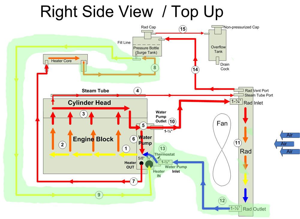 |
The areas where restriction are high are said to be the "high pressure" side of the system, and areas where restriction to flow are low are said to be the "low pressure" side of the system. Essentially, the low pressure side is the area after the heater and rad core up until the return (or inlet) side of the water pump. In this pic the low-pressure side is shaded in green, everywhere else is considered the high pressure side. In general, the radiator tank after the core and the return line to the pump, along with the return line from the heater are the low pressure side. Don't worry about all the other details in this pic at this time, we'll cover them in good time. |
||||||||||||||||||||||||||||||||||||||||
Cooling System ComponentsThe following are the basic components of any cooling system and so this section applies to any vehicle or any engine. Following this we'll have a look at some more specific GM Gen III/IV V8 ("LS") cooling system tech. |
|||||||||||||||||||||||||||||||||||||||||
 |
Water Pump The water pump is a centrifugal-type non-fixed-displacement pump that circulates the coolant through the block and heads where it collects heat from the engine, and then through the radiator where it is cooled by air flowing through the rad. The simple rule with water pumps is - the higher the flow the better. The reason for this will become clear later (and don't ever listen to anyone who says a water pump can flow too much and not let the coolant cool down in the radiator - pure myth. But I'm getting ahead of myself). |
||||||||||||||||||||||||||||||||||||||||
 |
Coolant The coolant is the liquid lifeblood of the system. Its job is to absorb the heat from the engine, and then give-up this heat in the radiator as air flows over the vanes attached to the tubes that carry the coolant. Coolant must also condition and lubricate the seals in the water pump and, in all but the most rigorously maintained race vehicles, inhibit corrosion in the many passages of the cooling system. Finally, in vehicles run in colder climates, the coolant must not freeze. An entire separate article could be written around the debate over coolant types and brands. Rather than get into all that here, let's just stick to the basics. |
||||||||||||||||||||||||||||||||||||||||
Heat (or heat energy) is measure in units called British Thermal Units (or BTUs). A BTU is the amount of energy required to raise 1 pound of water 1°F. Without knowing anything about thermodynamics, it's obvious that the best coolant is one that can absorb and give off the most heat energy per degree of temperature change it experiences - in other words it should be able to absorb and carry away a lot of heat energy without getting too hot itself. This property is called "specific heat". A liquid's specific heat is the number of BTUs it takes to raise the temperature of one pound of that liquid 1° F. In other words, the higher a liquid's specific heat, the more heat energy it can absorb per degree of temperature rise. We want the coolant to absorb a lot of heat energy while suffering the lowest temperature rise possible - that way the coolant can carry away the most heat without getting too hot itself and boiling. If the coolant boils it becomes a vapour (gas) and is now useless to us. It turns out that plain old distilled water has the highest specific heat of all liquids commonly used for coolant. Water has a specific heat of 1 - meaning one pound of water can absorb 1 BTU for a temperature increase of 1° F. A 50/50 Ethylene Glycol / water mix has a specific heat of 0.5, meaning it takes only 0.5 BTUs to raise the temperature of 1 pound Ethylene Glycol / water mix 1° F. A 50/50 Propylene Glycol / water mix has a specific heat of only 0.3. Therefore, it takes twice as much heat to raise a pound of water 1° F than a 50/50 Ethylene Glycol mix; and over three times as much heat to raise a pound of water 1° F than a 50/50 Propylene Glycol mix. Ultimately, what this means is that straight water can carry away 50% more heat than 50/50 Ethylene Glycol mix and 70% more heat than 50/50 Propylene Glycol mix per degree per unit volume. Of course, how much heat a liquid can absorb without boiling is also a function of the pressure acting on that that liquid. The boiling point, also called "vapour point" is that temperature where a particular liquid turns to vapour - which we don't want. Now - the more pressure a liquid is under, the higher its boiling point. This is precisely why cooling systems are pressurized. In the case of water, our most efficient coolant, we all know that at atmospheric pressure it boils at 100°C or 212° F. However, if we pressurize the water, its boiling point increases as follows:
We can see from the chart that, if we were running straight water, un-pressurized, it would boil at 212° F - which is no good as this is perilously close to the designed normal operating temperature of many modern engines. However, if we pressurized that water to even only 10 PSI, it wouldn't boil until 239° F. Many modern vehicle cooling systems are pressurized to 14-18 PSI, high performance systems to 22-24 PSI, and racing systems to 29-31 PSI. At the extreme end of the scale, Formula 1 race cars pressurize the coolant to as much as 50psi and have engine operating temps of about 265° F. Now, at atmospheric pressure, both Ethylene Glycol and Propylene Glycol have higher vapour points than water, and this trend continues at higher pressures. That means they will not boil until they reach higher temperatures which in turn means a) that they can continue absorbing and transferring heat at temperatures higher than water is capable of and b) that they provide a greater safety margin against coolant boiling. Commercial coolant mixtures also have a lower freezing point than water and contain additive and conditioning packages to lubricate and inhibit corrosion in the cooling system. Ultimately, which coolant to use will depend on your circumstances. For most, the benefits of an Ethylene Glycol mix or perhaps even a Propylene Glycol mix outweigh its lower efficiency. Of course, rather than run the normal OEM-recommended 50/50 mix, one can always custom tailor a mix to gain some of the advantages of a coolant mix while retaining as much of the efficiency of straight water as possible (e.g. a 75% water / 25% Ethylene Glycol mix). If you do - be sure to check that the vapour point and freezing point of the custom mix meets your system's needs. This is normally indicated in a little table on the bottle. However, for those running vehicles at the top edge of performance that see rigorous regular maintenance and are never subject to freezing temperatures - straight distilled water is undoubtedly the most effective liquid to use for coolant. Many folks who do run straight water will also add a small bottle of seal conditioner / corrosion inhibitor, such as Prestone Super Anti-Rust, to keep the water pump happy. |
|||||||||||||||||||||||||||||||||||||||||
 |
Radiator The heart of the system, a high-quality, appropriately-sized radiator is the single most important component in the cooling system. We'll look at how to spec a radiator, who makes the best, and what the best features are, in great detail later in the article. The short story is: Get the biggest aluminum radiator from Griffin Thermal Products that you can possibly fit!
|
||||||||||||||||||||||||||||||||||||||||
 |
Fan(s) and Shrouds Of course, a radiator is no use without a fan or two to pull air through it. By far the best fans are electrical "puller" fans - and the best of those are made by SPAL. Electric fans offer superior control, flow, mounting flexibility, and a host of other options not available from mechanically driven fans. In recent years, the popularity of front-wheel-drive cars with their transversely mounted engines that obviously must use an electric fan has led to major advances in electric fan performance and computer control that older mechanical fans can't match. |
||||||||||||||||||||||||||||||||||||||||
The only real choice for a performance cooling system is a "puller" fan - one that is mounted behind the radiator (in relation to the airflow) and sucks the air through the radiator. They are far more efficient than "pusher" style fans that mount in front of the radiator and push air through it. All fans should be shrouded. Without a shroud your valuable airflow is dramatically reduced and all manner of complicated aerodynamics can go on, essentially leaving your expensive performance rad and fan combo stifled and unable to do its job before it had a chance. |
|||||||||||||||||||||||||||||||||||||||||
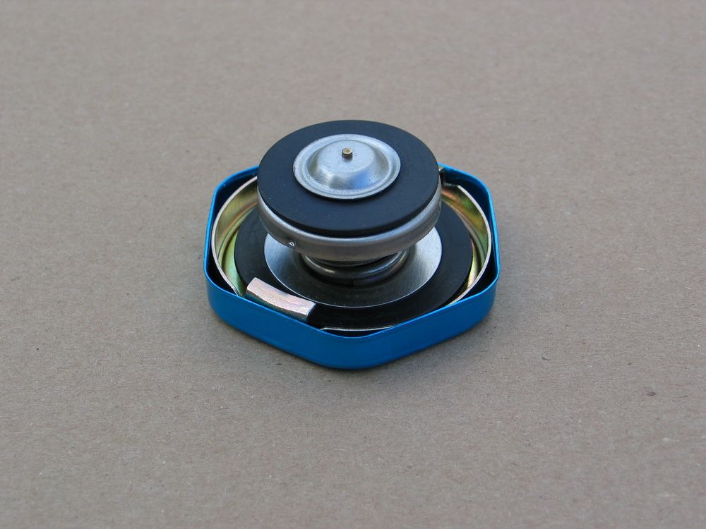 |
Radiator Cap The radiator cap is the "pressure relief valve" of the cooling system. It consists of a pressure-sensitive spring-loaded seal assembly that seals the cooling system from the atmosphere and thereby allows it to build the all-important pressure we were just talking about. In addition to raising the vapour point of whatever coolant is used, system pressure is vital for keeping coolant in contact with the metal surfaces of the cylinder heads and block. Consistent contact between the coolant and the engine passageways, particularly in the block and heads, is vital to prevent localized boiling or steam pockets in the combustion chamber areas of the cylinder heads. |
||||||||||||||||||||||||||||||||||||||||
Also, block pressure must be adequate to ensure uniform coolant distribution from the front to the rear of the engine. Low pressure can often result in insufficient cooling around the rear cylinders - which is why certain engine problems always show up first in the rear cylinders. Steam pockets or localized coolant boiling can occur when excessive heat is generated (because of a lean condition, excessive ignition advance, or faulty cooling system) causing the coolant to reach its vapour point and spontaneously change state from liquid to gas - in other words - boil. This is sometimes referred to as "flashing to steam". The problem usually occurs first in the combustion chamber area because it is the hottest region. When this happens - a vicious cycle begins - cylinder head hot spots cause steam pockets - steam pockets tend to "stick" in the highest area (the head) - steam cannot contribute to cooling and displaces much needed coolant - the excessively hot cylinder head experiences detonation and/or pre-ignition - which in turn creates excessive heat which causes hot spots and localized coolant boiling and steam pockets to form and so on. Adequate system pressure (along with a properly functioning cooling system and properly tuned engine) helps ensure that the coolant's boiling point is sufficiently high that the formation of steam does not occur and the cycle cannot begin. Keeping the coolant under pressure also helps to prevent cavitation in the water pump. The pressure in the cooling system comes from two sources. The first is from the action of the water pump pumping the coolant through the restricted passageways and plumbing of the cooling system. Secondly, since the cooling system is a closed and sealed system and liquids are both incompressible and expand when heated, pressure in the system results from the normal expansion of the coolant in the system as it heats up. Normally 12-17 PSI pressure is created when the coolant expands as a result of going from ambient temperature to normal engine operating temperature. The radiator cap serves to regulate maximum system pressure. A properly functioning cooling system in good working order will not normally generate excessive pressure. But under certain conditions like excessive heat generation or component degradation/failure system pressure can build well beyond normal. If this pressure were allowed to build unchecked, eventually component damage would occur - including hoses blowing off, seals being blown, and damage to the pump and radiator and any other component not able to withstand the elevated internal pressure. To avoid this, a radiator cap (safety valve) is installed that is designed to open at a certain pressure. A calibrated spring normally holds a seal in place that keeps the system sealed and pressurized. However, if system pressure builds beyond the opening pressure of the cap, the spring force is overcome, the seal retracts from its seat, and the system is opened to atmosphere. When this happens, excess pressure and fluid volume is allowed to bleed off in a controlled manner to a recovery tank, through a small fitting located just above the seal seat. The rad cap also serves as the point of entry for filling the system with coolant and for bleeding the air out. The rad cap must be installed at the highest point of the system. Often this is on the radiator itself, but when this is not possible due to the position of the radiator (i.e. the top of the rad is not the highest point in the system), the rad cap may instead be installed on a pressurized surge tank, as we shall soon see. As we previously discussed, because pressure drop increases as the coolant flows from the pump, through the system, and back to the pump, system pressure is not equal everywhere. This is an important consideration in rad cap location. The rad cap operates on the system pressure at its location. If it were located in the highest pressure portion of the system (the pump outlet or radiator inlet), it would regulate system pressure based on that highest pressure, meaning pressure elsewhere (for example, in the back of the cylinder heads) would be something less than the rating on the rad cap. This could mean pressure in the critical engine passageways could be as much as 10 PSI or more lower than the rad cap pressure rating - which is not good for cooling performance. It's also difficult to accurately measure system pressure at all locations, so you probably wouldn't even know how low the pressure was in the cylinder heads with the rad cap installed in the high pressure side of the system. In other words, with this arrangement, you may install a 20 PSI rad cap and expect coolant boiling point to be 259° F, but actual pressure in the heads, where boiling would occur first, would be less - perhaps only 10 PSI, and therefore actual coolant boiling point would only be 239° F - some 20° F less than you think! For this reason, the rad cap must be located on the low-pressure side of the system - either on the appropriate rad tank or on a remote-mounted surge tank. Regardless of the location, the best advice is to run the highest rated cap the design and construction of the system will allow. For the dedicated seeking ultimate cooling performance, this may take some messy and risky trial and error - most often the result of a cap rated too high is a blown hose, but it could also lead to a cracked radiator. Some common values are: Stock: 14-18PSI The rad cap also has a spring-loaded valve that can open to allow coolant entry back into the engine - described below in the section on "overflow tanks". |
|||||||||||||||||||||||||||||||||||||||||
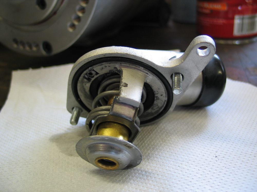 |
Thermostat The thermostat is the "brains" of the cooling system. Recall how we said that the job of the "cooling" system was actually to regulate or control the temperature of the engine to keep it as close as possible to the designed normal operating temperature at all times? It is the thermostat that accomplishes this.
|
||||||||||||||||||||||||||||||||||||||||
The thermostat is located in an area between the engine and the radiator. The classic small-block Chevy V8 located the thermostat on the "outlet" side of the motor, in the intake manifold. When cold, the thermostat was closed, and this prevented flow of coolant to the radiator. When the engine warmed up, the thermostat opened and coolant was allowed to flow to the radiator and back to the engine. The newer third- and fourth-gen GM V8's locate the thermostat on the "inlet" side of the motor - specifically in the inlet housing of the water pump. With this design, when cold, coolant is pumped through the rad, but is prevented from returning to the engine until the temperature of the thermostat has been reached, at which point the thermostat opens and the cooled coolant returns to the engine. Similar to a rad cap, a thermostat contains a spring-loaded sealing mechanism - but instead of reacting to pressure, it reacts to heat. Most thermostats do this with what is called a "wax motor". The wax motor is a cylinder containing a wax pellet that acts directly on the thermostat piston. As the wax heats up, and expands, it forces the piston to open the seal and allow coolant to pass. The Gen III/IV inlet thermostat location is designed to eliminate the following conditions / problems:
|
|||||||||||||||||||||||||||||||||||||||||
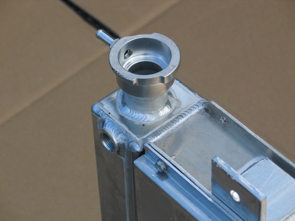 |
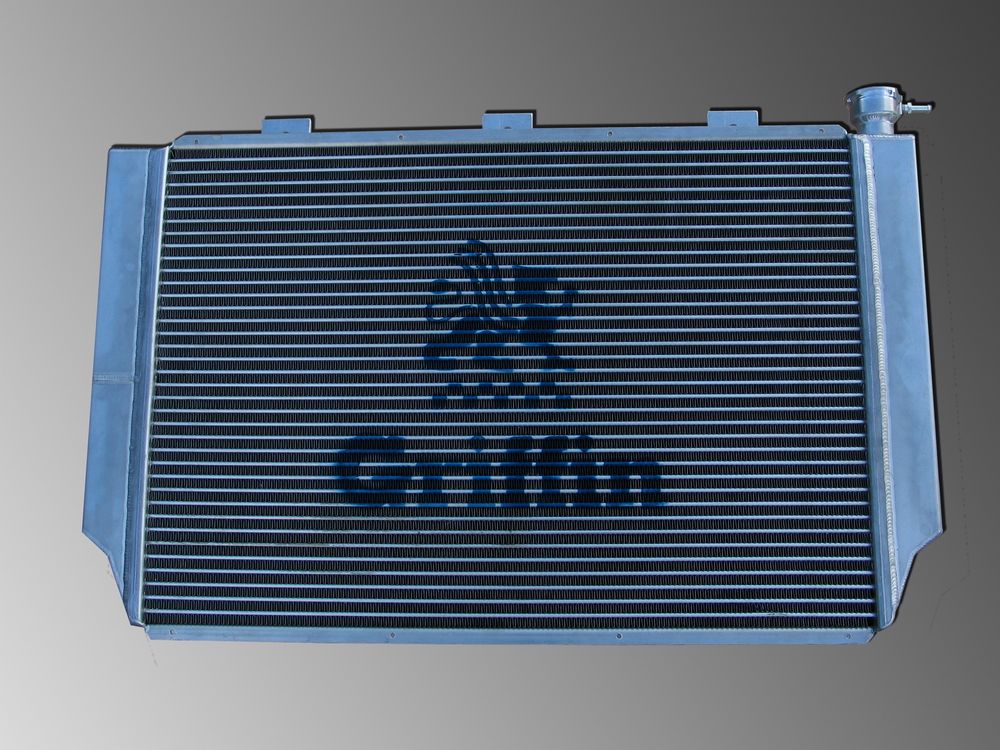
Overflow Tank All systems, regardless of whether they also use a pressurized "surge tank" or not, must use an overflow tank. Also known as an overflow catch tank, overflow bottle, catch can, expansion tank, or recovery tank the overflow tank has a simple installation and job. It merely connects to the "dry", outside, non pressurized area immediately below the rad cap but above the rad cap seal, so that in the event the rad cap opens due to overtemp/overpressurization, the hot coolant and gas that is expelled is collected safely. This pic illustrates the filler neck on my Griffin rad, where you can clearly see the outlet to the overflow tank above (or "on the dry side") of the rad cap seal seat. |
||||||||||||||||||||||||||||||||||||||||
 |
The overflow tank is not to be confused with a surge tank or coolant recirculation tank - though they do appear similar. The overflow tank serves no function in the normal operation of the coolant system. It only comes into play if there is an overpressurization and the rad cap opens, and then it only serves as a safe, environmentally responsible collection point for expelled coolant. If the system pressure reaches the cap’s pressure rating, the cap’s spring is compressed, forcing the valve open and allowing coolant to escape through the overflow tube to the overflow tank. After such an event, as the system cools it contracts, creating vacuum that opens the other spring- loaded valve, in the rad cap, allowing coolant in the overflow tank to be sucked back into the radiator. |
||||||||||||||||||||||||||||||||||||||||
The overflow bottle can be distinguished from the surge tank / recirculation tank in that:
The differences between the two will also become more clear once we get to the section on plumbing. |
|||||||||||||||||||||||||||||||||||||||||
 |
Surge Tank The surge tank is a completely different animal from the overflow tank. It is an integral part of the cooling system through which coolant continually flows. The surge tank also goes by many other names, adding to the common confusion between it and the overflow tank. You may see it referred to as a recirculating expansion tank, pressure tank, recirculation tank, coolant expansion fill tank, de-aeration tank, and others. A surge tank serves two purposes. First it allows for "remote mounting" of the rad cap in situations where the top of the radiator is not the highest point in the system. Secondly, it serves as a de-aeration chamber, allowing for continual and effective removal of any vapour (air or vaporized coolant / steam) in the system. |
||||||||||||||||||||||||||||||||||||||||
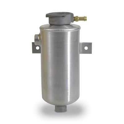 |
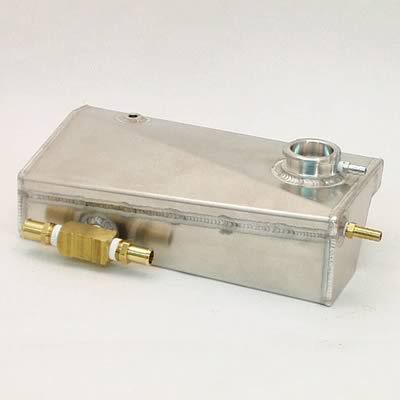
How it does this we will examine in detail in the section on plumbing. For now, understand that, unlike the overflow tank, the surge tank is plumbed "inline" in the cooling system and therefore has coolant continually circulating through it, and is therefore a pressurized component of the system. Surge tanks may come in many different forms. The one pictured above is a "Corvette style" tank, and the one pictured to the left is a generic aftermarket one. |
||||||||||||||||||||||||||||||||||||||||
Regardless of its exact form, a surge tank can be distinguished from an overflow tank by the fact that:
It is also important to note that the surge tank does not take the place of the overflow tank - it is used in addition to the overflow tank. This can be seen in both the examples above where you can clearly see the fitting in the filler neck (the overflow tube) that connects to the overflow tank - exactly the same way it does when the filler neck / rad cap are mounted directly to the radiator. |
|||||||||||||||||||||||||||||||||||||||||
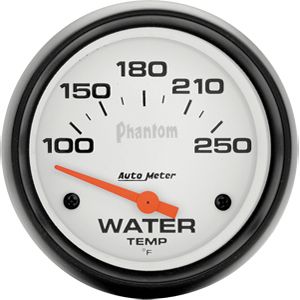 |
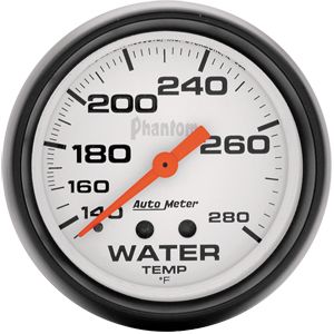
Temperature Gauge Of course, it's important that you be able to monitor the performance of your cooling system, so a high quality gauge is a must. Not being an article on gauges and instrumentation, I won't go into all the details of selecting gauges here, except the following important considerations. From my aviation experience, it is a good idea to have the normal operating condition of all gauges appear at a consistent location on the gauge, normally at the 12 o' clock position. This way, a quick glance is all that is required to verify that all "temperatures and pressures are in the green" (meaning all OK). |
||||||||||||||||||||||||||||||||||||||||
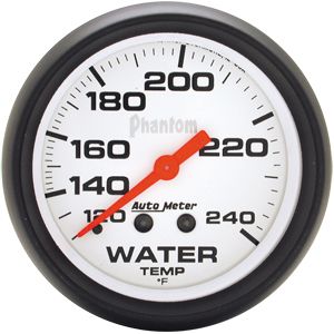 |
Different gauges have different temperatures at the 12 o' clock position, as can be seen from the accompanying photographs. Depending on the designed operating temperature of your engine, when selecting a gauge, along with other considerations you should consider selecting a gauge that displays the correct operating temperature at the 12 o' clock position. The gauges pictured here appear in order from coolest to warmest in terms of the temp indicated at the 12 o' clock position; in order 180° F, 200° F, and 230° F. |
||||||||||||||||||||||||||||||||||||||||
 |
This leads me to the other point. We often talk, as I have done here, as if the temperature on the gauge were the temperature of the engine, but this isn't entirely accurate. What the gauge reads is the temperature of the water, or coolant, at the position of the sensor or sending unit - it's even marked right there on the gauge "WATER TEMP". This can be an important consideration when selecting where to mount the sensor or sending unit. We must also understand the distinction between this water temp and the actual temp of the engine. |
||||||||||||||||||||||||||||||||||||||||
| Coolant temperatures do not accurately reflect actual metal temperatures in the engine. The metal can be several hundred degrees hotter than the adjacent coolant.
This means, depending on the gauge sending unit location, coolant temperatures may read "normal" while the actual temp of the cylinder heads, for example, may be excessive. Therefore, the location of the gauge's sending unit or sensor must be chosen carefully
- somewhere in the cylinder head is often a good choice.
Assuming the gauge sending unit is properly located, an engine typically runs most efficiently when the coolant temperature is kept around 200° F. This comes back to maintaining the proper operating temperature again. At this temperature, the combustion chamber is warm enough to completely vaporize the fuel mixture for improved combustion, and the oil’s viscosity is at the right point so that it can properly lubricate the engine and present minimal parasitic drag. An engine that is too cold is no good! Do not try to design your cooling system so that your engine runs all day at 160°F! For most "normal" engines, 250°F is about the greatest water temp indication you should tolerate. Beyond this and the engine should be shut down or allowed to idle until it cools down. Incidentally, this is another advantage to electric fans. Because an electric fan can continue to run when the engine is not running, and because hot coolant will rise and be replaced by cooler coolant, and because the rad inlet is at the top and the engine inlet at the bottom - coolant will circulate and you can actually cool the engine even when it isn't running. | |||||||||||||||||||||||||||||||||||||||||
LS Cooling SystemsWhile the previous information is applicable to virtually any cooling system, this section will deal with the specifics of the cooling systems on third and fourth generation GM V8 engines, and in particular my Turnkey Engine Supply LS2. The following illustration is a diagrammatic representation of a generic "LS" cooling system, complete with heater.
Starting at the water pump and following the numbers in sequence, here's the flow of the system:
As can be seen, the surge tank is an important and very useful component of the system. Following are a few more details on the use of a surge tank: One of the prime reasons for mounting a pressurized surge tank in the cooling system is the flexibility it gives in the mounting location of the rad cap. Because it is the pressure relief valve of the system, the rad cap:
The surge tank provides the ideal environment for satisfying all three of these requirements, and provides a low velocity, low-pressure environment for de-aeration of the coolant. When plumbing a surge tank:
The continual de-aeration that a surge tank provides can be a huge benefit to your overall cooling system. We already discussed all the bad things that happen when steam or air are trapped in the cooling system. In addition to those, consider that 2% air in the system results in 8% less heat transfer, but 4% air results in a whopping 38% less!! The continual de-aeration of the coolant may be enough advantage to allow you to run a smaller, easier-to-fit radiator with a surge tank than the size you would have to run with only an overflow tank, for instance. If your engine doesn't have steam ports, and the rad is lower than the top of the engine, the bleed line to the surge tank must come from the highest point on the engine because this is where steam and air will naturally gravitate and get trapped. A fitting on the water pump in the same passage as the outlet to the radiator can be a reasonable compromise. If you add a surge tank to a system that already has a rad cap on the radiator, you need to permanently seal the radiator rad cap location, or at least install on the rad a cap with a rating significantly higher than the surge tank cap will have, so that the radiator mounted cap will not open before the surge tank cap. Now, here's a close look at some of the other components in the "LS" cooling system: |
|||||||||||||||||||||||||||||||||||||||||
|
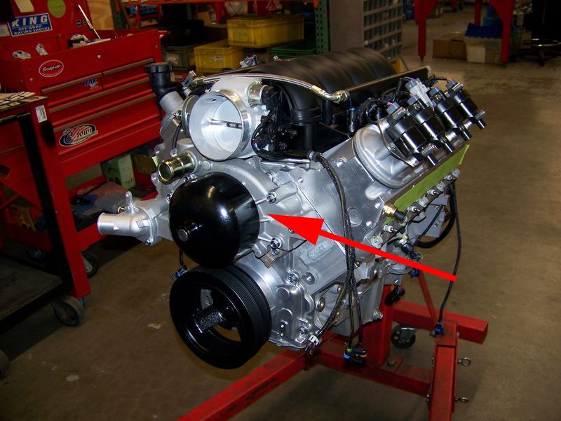
Here's the water pump mounted to the front of the engine. This particular example is a 2002 Camaro LS1 water pump mounted to my Turn Key Engine Supply LS2. The pump is a belt-driven, cast aluminum unit of centrifugal non-fixed-displacement design with a double-shrouded impeller to improve pumping efficiency and total pump output. The pump incorporates a crossover / bypass circuit as described above, 1.25" outlet, 1.5" inlet, and integrated thermostat housing with heater outlet (5/8") and inlet (3/4") ports, located on the engine side of the thermostat just inside the radiator inlet. |
||||||||||||||||||||||||||||||||||||||||
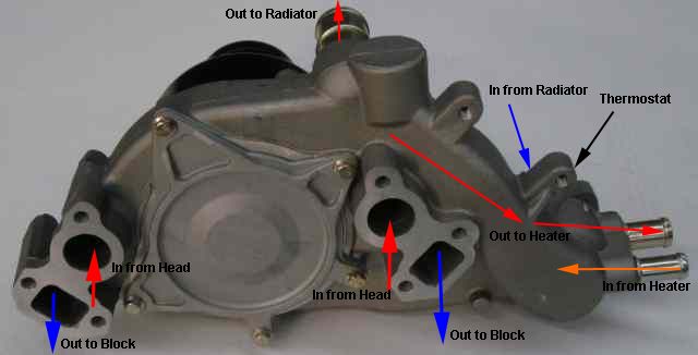 |
Back side of the water pump showing coolant flow path. | ||||||||||||||||||||||||||||||||||||||||
 |
A = Water pump outlet to heater core, 5/8". B = Water pump inlet from heater core, 3/4". C = Water pump inlet / thermostat housing (in to engine from radiator), 1-1/2". N = Water pump outlet (out to radiator, from engine), 1-1/4". |
||||||||||||||||||||||||||||||||||||||||
 |
Coolant passages in the block. Note the block has siamesed bores. This means there are no water passages between the cylinder bores. A lot of development went into the design of the Gen IV water jacket to get good heat rejection without the need for water between the bores. |
||||||||||||||||||||||||||||||||||||||||
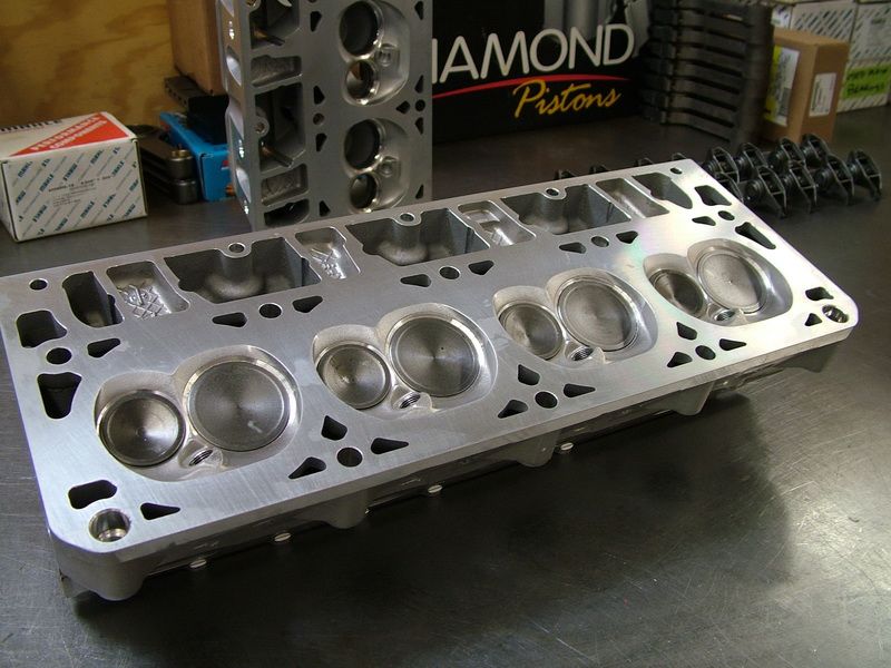 |
Coolant passages in the cylinder head. | ||||||||||||||||||||||||||||||||||||||||
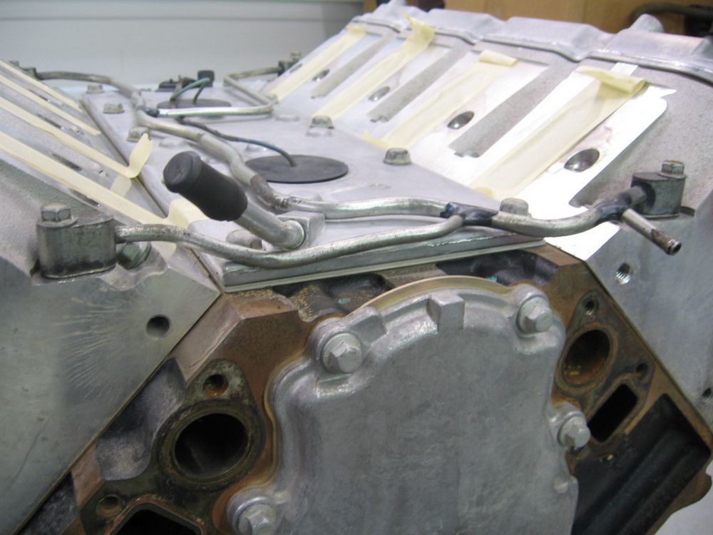 |
This picture illustrates the LS "steam tubes", also known as "coolant vent lines" or "engine bleed lines". You can see that the lines originate at ports in the front and rear of the left and right cylinder heads. This picture is of a car engine, the truck engines had steam tubes originating only from the front of both heads. Most stock "LS" engines had these steam lines routed to the top low pressure side of the rad, although some applications ran them directly to the surge tank. |
||||||||||||||||||||||||||||||||||||||||
I hope by now that you can see why simply capping the steam ports at the cylinder heads is a really bad idea as this will allow steam to get trapped exactly where it can do the most damage. You may also read where folks run the steam lines back into the low pressure side of the cooling system - sometimes by putting a fitting on the thermostat housing, and sometimes by plumbing them directly back into the heater core return port. I imagine that the hope is that any steam pockets will then go back into the general cooling system flow with the hope that they would eventually migrate back to the area below the rad cap, wherever it may be. I have to be honest - this strategy makes no sense to me at all and is not supported by the laws of thermodynamics. It seems to me that doing this is asking for the steam to just re-circulate until it gets trapped somewhere at the highest point of the system - possibly in the steam line itself before it turns down to go to the low water pump inlet. Regardless, the best strategy is to plumb the LS steam tubes either to the high point of the low pressure side of the rad or directly to a surge tank. |
|||||||||||||||||||||||||||||||||||||||||
 |
P = steam tube outlet at front of my LS2 right cylinder head. This must be plumbed either directly to a surge tank, or to a port at the top low-pressure side of the radiator tank (not the side with the radiator inlet). | ||||||||||||||||||||||||||||||||||||||||
|
LS1 thermostat located in the integral thermostat / pump inlet housing. This particular thermostat is rated at 180°F.
|
||||||||||||||||||||||||||||||||||||||||
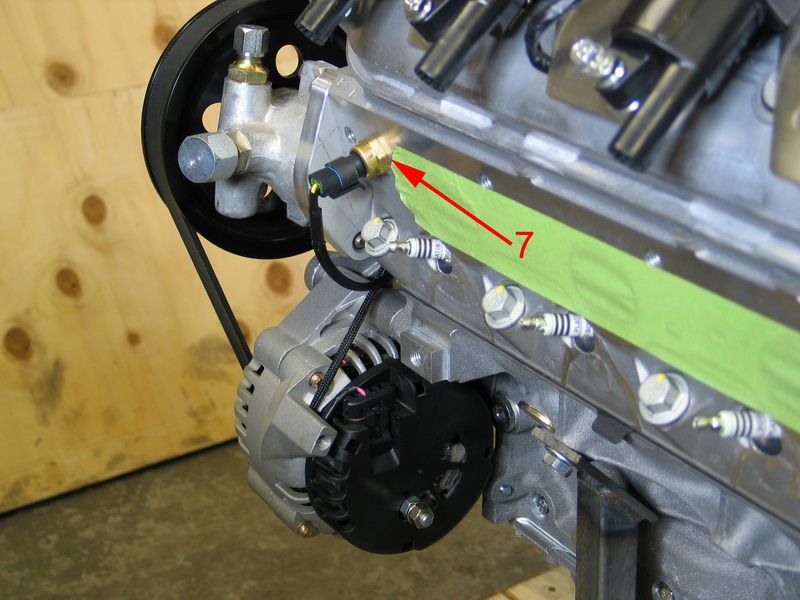 |
7 = Coolant Temperature Sensor (CTS). The CTS monitors engine temperature and tells the Engine Control Module (ECM) when the engine has reached or exceeded normal operating temperature. CTS data is used in a wide range of functions, from telling the ECM when to use cold start-up enrichment mode to turning on the electric radiator cooling fans to fuel/spark adjustments and engine over-temp protection. |
||||||||||||||||||||||||||||||||||||||||
The coolant temperature sensor provides important fueling information to the ECM when the engine is below its normal operating temperature. Cold engines require more fuel to operate so the ECM uses the CTS information to enrich the air/fuel mixture in much the same way an automatic choke did on carbureted engines. Depending upon how cold the engine is, the ECM will increase the base pulse width values obtained from its main fuel table and then gradually taper off the increase as the engine warms up. The CTS is also used for several other temperature-dependent functions including: the modification of idle speed, IAC motor position, and spark advance as well as detecting engine overheat situations. |
|||||||||||||||||||||||||||||||||||||||||
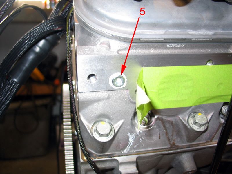 |
5 = 1/4" NPT port for electrical water temperature gauge. This port is a 12mm x 1.5mm metric fitting on the stock LS2, but on the Turn Key engine it is 1/4" NPT to match 99.9% of the gauges out there. This means that you don't have to try and make adapters or take the head off just to drill and tap for a gauge sender. |
||||||||||||||||||||||||||||||||||||||||
Recall what we were saying about the difference between the temp sensed by and indicated on the gauge, and the actual operating temperature of the engine. Combine this with the information above on the role of the CTS, and we see that it makes good sense to locate the gauge sensor (rear of right cylinder head) where it will get similar readings as the CTS (front of left cylinder head) so that we can see essentially the same data as the ECM does. Then, with some knowledge of the ECM's programming (which will be based on the designed operating temp of the engine) we can easily make informed decisions about the data displayed on the gauge. For example, on my engine, when engine temperature (as read by the CTS) reaches 235°F, the ECM goes into "limp home" mode where it limits rpm to 2000. |
|||||||||||||||||||||||||||||||||||||||||
 |
Overall shot of my LS2 showing all the coolant inlets and outlets. | ||||||||||||||||||||||||||||||||||||||||
LS Cooling System Plumbing VariationsNow that we've seen the design and components of the standard "LS" cooling system, let's have a look at a few possible variations based on swapping an "LS" motor into a non-oem vehicle. No HeaterMany engine-swap applications, be they hot-rods or off-road rigs, delete the heater core. The following diagram illustrates a cooling system where the heater has been deleted but a stock-like surge tank setup is maintained.
The system flow is as follows:
Aftermarket Surge TankUnlike the above system, this setup not only deletes the heater, but also uses an aftermarket surge tank. |
|||||||||||||||||||||||||||||||||||||||||
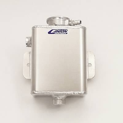 |
The "Corvette style" surge tanks that we have pictured so far are not very common. Much more common are aftermarket type surge tanks that have a single large lower return port (usually 1/2" NPT or AN -10) and one or more smaller (1/4" or 3/8") upper inlet ports, such as this one from Canton... |
||||||||||||||||||||||||||||||||||||||||
|
... or this one from Afco. | ||||||||||||||||||||||||||||||||||||||||
The following diagram assumes an aftermarket surge tank with two inlet ports. If a dual-inlet surge tank were not available, a similar system could be run but the engine steam tubes would have to be run to the rad, and the rad vent port run to the single surge tank inlet.
In this system:
Old School - Overflow Tank OnlyThough it eliminates the advantages of the surge tank, depending on the capabilities of the rest of your cooling system, it is possible to run a system with just an old-school overflow tank. Of course, this requires that the rad cap be mounted on the rad and that the rad be the highest point in the system. It also demands that the rest of the cooling system be capable enough that the advantages of the surge tank design can be safely done away with. However, with a good enough system, and especially a big enough rad and good enough airflow, eliminating the surge tank can save you some space (as their is no need to find a place to mount the surge tank), save a little plumbing, save a little weight, and simplify the system a little. |
|||||||||||||||||||||||||||||||||||||||||
 |
There are a huge number of overflow tanks available from the aftermarket. This one from Canton incorporates a sight-tube for checking the coolant level in the tank, as well as a non-pressurized cap. |
||||||||||||||||||||||||||||||||||||||||
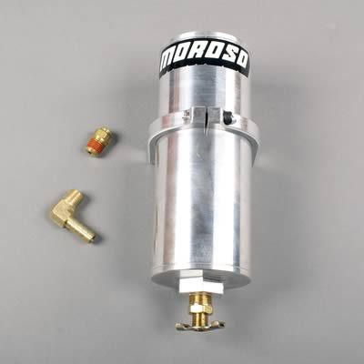 |
This one from Moroso has neither a sight-tube, nor a cap. | ||||||||||||||||||||||||||||||||||||||||
The following is the simplest of all systems we shall look at, and there is a certain beauty in simplicity. It deletes the heater and the surge tank. However, it forgoes the continual de-aeration capabilities of the surge tank and requires that the rad-mounted rad cap be the highest point in the system. Note however, that the steam tubes are still correctly plumbed to the radiator. Of course, never plumb the steam tubes directly to an overflow tank!!
In this system:
Blocking the LS Heater PortsIn many of the systems I've illustrated, as in many custom engine transplants, the heater is deleted and the heater ports blocked off. Here's how to block off the LS heater ports. |
|||||||||||||||||||||||||||||||||||||||||
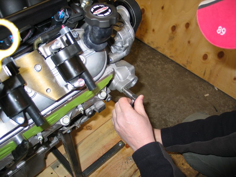
 |
Unbolt and remove the engine inlet/thermostat housing and thermostat. Firmly grasp the heater hose fittings with vise grips, twist, and remove from the housing. They are only pressed in and this will cause no damage. |
||||||||||||||||||||||||||||||||||||||||
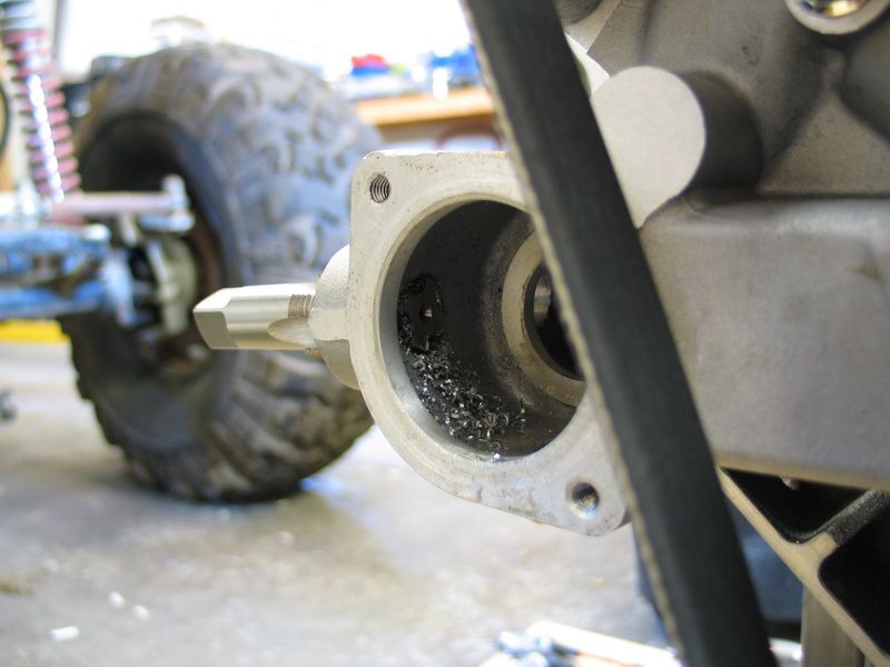
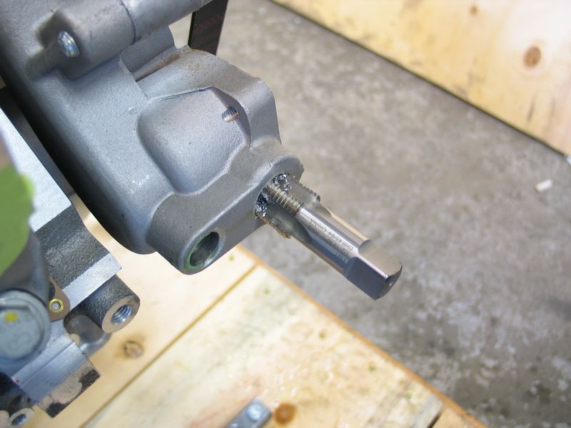 |
Using a 1/2" NPT tap for the larger "in" port (shown) and a 3/8" NPT tap for the smaller "out" port, carefully tap the ports. You do not need to drill the ports to size prior to tapping. |
||||||||||||||||||||||||||||||||||||||||
 |
Be sure to follow all the normal good practices of tapping a hole - lubrication, back out the tap to clear the chips, etc. You don't want to screw it up and have to buy a whole new water pump! |
||||||||||||||||||||||||||||||||||||||||
 |
The chips will collect in the pump housing. | ||||||||||||||||||||||||||||||||||||||||
 |
And can easily be vacuumed out when you're finished. | ||||||||||||||||||||||||||||||||||||||||
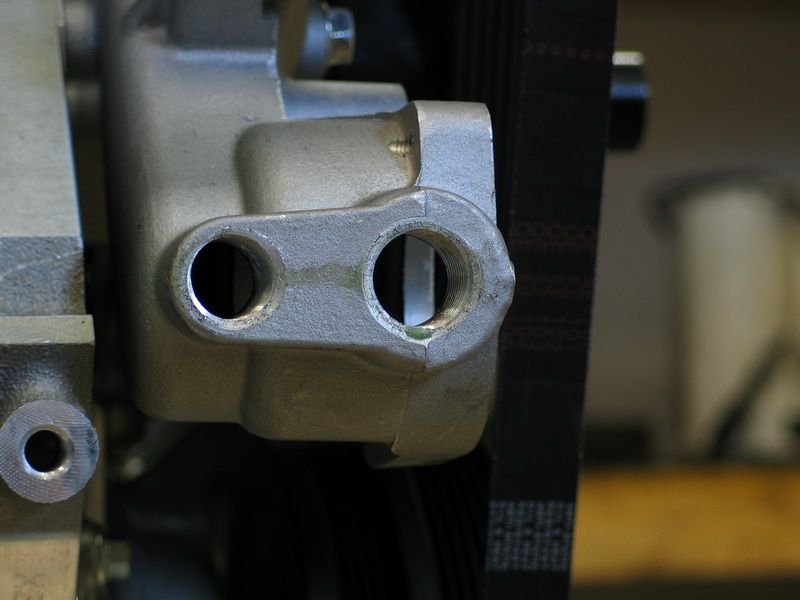 |
Threads cut. | ||||||||||||||||||||||||||||||||||||||||
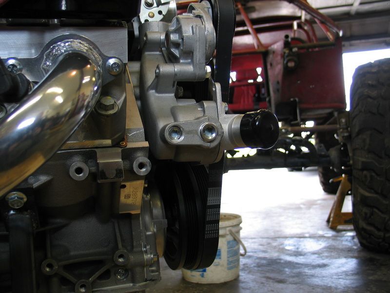 |
NPT plugs installed with PTFE sealing tape. | ||||||||||||||||||||||||||||||||||||||||
How to Build a Killer Cooling SystemOK, so now we know all the basics - what the parts are, what they do, how the system flows and is plumbed, what pressure does for us, etc. Now - what distinguishes a good, capable cooling system from a lousy, inadequate one? How do you begin to design or build a cooling system for your rig? The quick answer is, you should maximize:
Here are Griffin's "10 Commandments for Maximum Cooling". I agree with them all (I'm sure they'd be relieved to hear that ;-) as they apply to most normal, street-driven vehicles. For race or other high-performance vehicles the only exceptions I would take are with regards to the the pressure of the rad cap and the percentage of Ethylene Glycol or Propylene Glycol in the coolant, as we have discussed. Now we will cover some tech details and advice on selecting the main components for any cooling system, but focusing especially on a cooling system for an offroad rig powered by a Gen III or IV GM V8 The RadiatorFirst - let's just go over the main parts of the radiator, because, as usual, some folks insist on using terms loosely or incorrectly which can lead to confusion.
The tanks are connected by the tubes. Coolant enters the tank with the inlet port, and flows between the tanks via the hollow tubes (which are actually very wide and thin in cross section, not round). Sandwiched between the tubes are the fins. The part that forms the actual joint between the rows of tubes and the tanks is called the header - you can't distinguish it in this pic, but you will see a pic of the header later when I show you a Griffin Rad being built. The combination of all the tubes and fins together is called the core. Thus, the two major components are the core and the tanks. The core will always have many rows of tubes between the top and bottom of the rad, but it may also have one or more rows of tubes (from front to back) for each "row" between the tanks. You can't easily tell this, because the rows of tubes would all be one behind the other. Some folks interchange the word "core" for "tubes" so that you may hear them say they have a "3-core rad". What they mean is that the core of their rad uses 3 rows of tubes, one in front of the other, for each "row" between the tanks - not that the rad has 3 complete cores!
There is no one magic formula to spec'ing, buying, or building a top quality radiator. There are many complicated inter-related factors at play and designing and building a great radiator is both art and science. Fortunately, this is something Griffin Thermal Products are very, very good at. Keep in mind, as you read the following considerations that a radiator is only as good as the sum of its parts, that there is a lot more to a quality radiator than meets the eye, and that there are few hard-and fast rules, despite what some would have you believe (for example, you can't say that a 3-row rad is always better then a single-row rad.) As you read this section, keep in mind that the job of the radiator is to expose as much hot coolant as possible to the inside surfaces of the rows of tubes that connect the radiator tanks. Heat is thus transferred from the coolant to the tubes. From the tubes, the heat is transferred to the fins. Airflow passing over the fins then dissipates the heat into the air. That said, here are some of the factors to keep in mind when selecting or spec'ing a radiator: MaterialThere is only one choice of material for a top-quality radiator today - aluminum. Not only does it have a very efficient rate of heat transfer - it also has far superior structural strength compared to an older copper core radiator. This means the radiator will be able to withstand higher system pressures. The greater strength of aluminum also means the aluminum radiator can be built with wider tubes which allow more direct contact between the coolant and the tube surface as well as more contact between the fins and tube, both of which increase the radiator’s capacity to dissipate heat. Because of these wider, more efficient tubes, an aluminum radiator with 2 rows of 1" tubes is equivalent to a copper radiator with 5 rows of 1/2" tubes! The greater structural strength of aluminum also means that radiators can be built with very wide cores without risk of collapse, which provides greater coolant capacity and greater cooling surface area. All things considered, an aluminum radiator will be more efficient, longer lasting, stronger, and lighter than a traditional copper radiator. Surface AreaSurface area is king. Get the biggest rad you can fit (length x width). In fact, if maximum cooling performance is your goal - consider getting a bigger rad than you can fit and then building the chassis around the rad. This is exactly what I did when building the cooling system for my 525HP LS2. I knew it made a lot of power. I knew power = heat. So I chopped off the whole front of the truck and built a new front end specifically around my Griffin rad. Surface area - yes, it's that important! There used to be an old-school rule that stated that a rad should be 1 square inch for every cubic inch of engine displacement. This was an old rule from back in the days when making 1hp per cu. in. was considered pretty high performance. These days engines are routinely making more than 1hp per cu. in. so the rule needs revising since cooling capacity is related to power and not just engine size. For high performance use - like offroad racing, my rule of thumb is to size a rad based on 1.1 sq. in. per hp produced. This is a fairly conservative rule of thumb, which works well for aluminum motors. Here are some common rad sizes and their areas in square inches:
TurbulenceIt is very important that the coolant flowing through the radiator's tubes does so in a turbulent or "rough and tumbling" fashion. This is so that the maximum amount of hot coolant can come into contact with the surface of the tubes so maximum cooling can occur. If the flow is not turbulent, but instead is smooth or "laminar" in nature, a thin boundary layer of fluid will tend to "stick" to the inside walls of the tube, insulating the rest of the fluid from the cooling surfaces of the tube. The result is, the outer boundary layer cools, but the hot inner core never gets cooled. The following diagram illustrates the difference between laminar (bad!) and turbulent (good!) flow.
There are a number of ways a radiator or cooling system designer can achieve turbulent flow. They include:
ThicknessIf you have maximized the surface area and there's absolutely no way to go any bigger, then there may be some advantage to using a thicker rad. Adding thickness to a radiator does not increase its efficiency to the same extent as increasing its surface area does, but as long as there is sufficient airflow it will not decrease the efficiency. Thicker radiators do have slightly more airflow resistance than thinner radiators but the difference is minimal at speed when there is good airflow through the radiator. Where issues can crop up is at idle when the fan(s) alone must supply the needed airflow. Use of a quality, properly shrouded fan or fans is a must to produce the required airflow at idle and slow-speed conditions. Of course, this is true to some extent in all case, but especially so with particularly thick radiators. RowsOne row? Two rows? Three rows? (Or erroneously, single-core? Double core? Triple core?) Which is the best? There is no hard and fast rule here. The number of tubes in each row (from front to back) is only a part of a radiator's overall design. One cannot say that two rows are always better than one. It all depends on the size and profile of the tubes, as well as all the other design features of the radiator - not the least of which is the overall size. The best bet is to choose or spec a radiator using the other criteria for which there are firm guidelines (aluminum, largest area possible, etc.) and then leave the other design elements, such as the number of rows, to a trusted expert such as Griffin. Fin DensityNormally, the greater the density of fins between the tubes, the more surface area there is to be subjected to cooling airflow. However, there is a limit - more is not always better and too much of a good thing becomes a bad thing. Imagine a fin density so high it was almost a solid - obviously that would not be optimal for cooling as no airflow could pass. Another factor involved in the optimal fin density calculation is the operating conditions to which the radiator will be subjected. Dirty, clogged fins are inefficient and even useless, and extremely dense fins are very difficult to keep clean. Not only that, but the fins are fairly delicate and cleaning them can sometimes cause damage that again reduces their efficiency or renders them useless. For these reasons, often the best choice for an off-road rig is a slightly less dense fin count compared to a street or track car - and the overall result will be better real-world, in-service cooling. Griffin understands this and, unlike some others, will not just sell you the product that sounds best on paper (highest fin density). Rather, they will take the time to understand your application and will either design a custom product for you or sell you an off-the-shelf product best suited to your actual needs. Flow - cross and downAlmost all radiators today are "cross-flow". This simply means that the tanks are on the sides of the core, and that the coolant flows horizontally through the tubes from one tank to the other. |
|||||||||||||||||||||||||||||||||||||||||
 |
A cross-flow radiator with tanks on the sides of the core. | ||||||||||||||||||||||||||||||||||||||||
| Years ago, most radiators were "down-flow" design where one tank was on top of the core and one was below so that the coolant flowed down, vertically, from the top tank to the bottom. This style is still popular today in some circles such as the hot-rod scene. | |||||||||||||||||||||||||||||||||||||||||
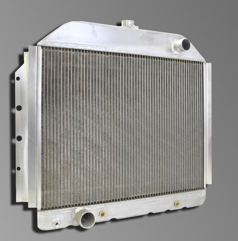 |
A down-flow radiator with tanks above and below the core. | ||||||||||||||||||||||||||||||||||||||||
Many, many myths and old wives' tales can be traced back to the old down-flow style radiators and their design and construction. We will deal with them in a separate section. For now, unless you are trying to reproduce a classic hot-rod look or are intent on replicating the factory setup in a rig that originally used a down-flow radiator, know that a cross-flow radiator is the better design because:
Flow - single-, dual-, triple-pass |
|||||||||||||||||||||||||||||||||||||||||
 |
The diagram at left depicts the flow in a single-pass cross-flow radiator. The tanks are completely open inside and coolant flows horizontally, in one direction only, from the inlet (high pressure) side to the outlet (low pressure) side. This results in the inlet and outlet being on opposite sides of the radiator. If a rad cap is mounted on a single-pass rad, it is located on the low pressure (outlet) side. |
||||||||||||||||||||||||||||||||||||||||
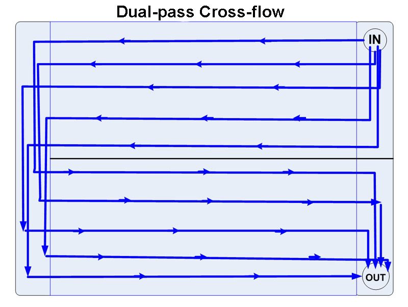 |
Pictured at left is a dual-pass cross-flow radiator. In this configuration, the inlet and outlet are located on the same side of the radiator, and the tank to which they attach is separated in half vertically. This forces the coolant to flow from the inlet to the opposite side tank, then back through the rad to the outlet, as pictured. This essentially doubles the length of the tubes between inlet and outlet, halves the cross-sectional area for flow, and results in:
|
||||||||||||||||||||||||||||||||||||||||
| Let's take a closer look at why all this is so and what it means to our cooling system performance.
Many people mistakenly believe that a dual-pass radiator cools better because the coolant "goes through the rad twice" and therefore "spends longer in the rad and cools more". We know that this is not the case, because "time spent in the rad" is not a defining factor of how well a rad cools, and that flow, turbulence, and delta-T have a far greater effect on cooling efficiency than time. In addition, there are a great many aspects of radiator design, including tube width, tube height, number of tubes, tube construction, and fin count that, in addition to flow pattern, all combine to determine the cooling efficiency of a radiator. So, the question is - does a dual-pass rad cool better or worse than a single cross-flow rad? The answer is "it depends". To understand why this is the case, we need to recall the principles of Pump Performance Curve and Total System Pressure Drop and apply them to the dual-pass rad to see what is happening. We already know that pressure and flow are related, and therefore how increasing the effective length of the cooling tubes with a dual-pass rad increases pressure drop (backpressure). If we examine the pump performance curve, we can also see how the increased head required by the increased backpressure of the dual-pass rad also causes a reduction in flow because the pump always performs somewhere on its curve, and since its head has increased, the flow it produces will be less. The following diagram illustrates the concept, but once again the values are not intended to be representative of any real-world conditions (I just made them up to illustrate the concept).
How large an effect on pump flow the increased head required for a dual-pass rad has, depends on the specific pump's performance curve and how large a part of the overall system pressure drop the rad is. Now, to understand the dual-pass rad's effect on coolant velocity, we need to introduce one last equation that relates flow, area, and velocity. Flow in a pipe (or radiator tube) is equal to the cross-sectional area of the pipe multiplied by the velocity of the fluid. If that concept is difficult to grasp, it may help to think of the units involved, as in: Flow (q) = Area (A) x Velocity (V); or cubic feet per minute = square feet x feet per minute
(note: 1 cu ft = 7.48 US gallons) This makes sense - the larger the pipe and/or the faster the fluid is moving - the greater the flow (the more fluid will pass through the pipe in a given time). Now, since q=AxV, this means that if you decrease the area or the velocity, the flow decreases; and by the same token, if flow remains constant and area is reduced, the velocity or speed of the fluid must increase. In a dual-pass rad like the one pictured above, the coolant only has half the number of tubes to flow through at a time - that is, the cross sectional area is halved. And because q=AxV, since the area has halved, for a given flow produced by the pump, the velocity of the coolant doubles. Because velocity increases, so does turbulence. Velocity also has a beneficial effect on the heat-transfer coefficient (how well the radiator sheds the heat in the coolant). Lastly, in a dual-pass radiator, the delta-T (temperature difference) between the coolant and the airflow will be less on the second pass than it is on the first pass - which means heat transfer from the coolant to the air will be less on the second pass than the first. So again, in general, when compared to a single-pass rad, the dual-pass rad has some degree of:
Of course, all this is also a circular process. Area is reduced -> velocity goes up -> pressure drop goes up -> head goes up -> flow goes down -> velocity goes down (remember q=AxV at all times) -> pressure drop goes down -> head goes down -> flow goes up -> and so on (the system quickly reaches a point of balance or equilibrium, it just isn't easy to calculate with a simple equation). There are two final considerations with regards to a dual-pass radiator compared to a single-pass:
How all these factors balance out and therefore the overall effect on cooling system performance of replacing a single-pass rad with a dual-pass rad depends on which, if any, of these factors is the limiting factor on that system's performance. Attempting to calculate and quantify this is a complex problem requiring advanced knowledge of fluid dynamics and thermodynamics and advanced modelling techniques. It is likely well beyond the ability of any enthusiast. The best we can do is understand the general principles at play, and then consult the experts as to whether or not a dual- or even triple-pass rad can or will be beneficial to your cooling system. One cannot definitively say that a dual-pass rad always cools better than a single-pass rad or vice-versa, but there are certainly cases where a dual-pass radiator can be very beneficial if applied to a properly engineered cooling system. The best advice I can offer is: before considering a dual-pass or triple-pass radiator for your vehicle be sure to consult cooling system professionals like those at Griffin Thermal Products. Inlets and OutletsInlets and outlets should be chosen to match the diameter of the water pump inlet and outlet. In the case of the "LS" motors the water pump outlet is 1.25" and the inlet is 1.5". They can be placed on either side of the rad, either together (as in a dual-pass radiator) or on opposite sides (as in a single-pass or triple-pass radiator). For older conventional V8's, Chevy engines normally had the rad inlet on the left and the outlet on the right. In Fords they were reversed with the inlet on the right and the outlet on the left. On the older gen I GM V8's the water pump outlet was usually 1.5" and the inlet 1.75". Filler Neck / Rad Cap LocationAs has been covered, if you are going to use a radiator with a filler neck and mount the rad cap to the radiator, the filler neck should always be placed on the low-pressure tank - i.e. the one that doesn't have the radiator inlet. Additional Ports & PlugsDue consideration should be given to the location and size of steam ports and surge-tank vent ports. Remember they should be located on the low pressure side, just below the rad cap. Most high performance rads do not incorporate a built-in drain plug at the bottom since this can create an unnecessary potential leak point and most racers wouldn't use a drain port for maintenance since the whole system usually comes apart for inspection and replacement as necessary when maintenance is scheduled. Griffin does not normally install a drain in their race radiators since most racers don’t use a drain, and, given the wide variety of chassis a race radiator can be used in, it would be impossible to find a location for the drain that would suit every possible application. AirflowThe best radiator does no good without adequate airflow. Airflow is measured in cubic feet per minute, or CFM. In your design, be sure to allow for adequate airflow at both high and low vehicle speeds. Airflow design for low speeds is fairly easy - you need one or more good quality, powerful fans and a good, complete shroud. Without a shroud you can loose as much as 50% of the CFM you would otherwise have. Ensuring good airflow at higher speeds is more difficult, because high-speed airflow can do weird and wonderful things and you need to account for aerodynamic flow and different air pressure zones. Rather than teach a class on aerodynamics, here are some basic tips:
FansAs previously mentioned, electric fans offer superior flow, mounting flexibility, and computer control compared to mechanical fans. Years ago, it used to be that mechanical fans offered the best performance, but today that isn't so. Mechanical fans are subject to problems with vibration due to air turbulence when run at high RPM. This can lead to premature wear on the water pump. Mechanical fans can also consume up to 20 or more horsepower. Viscous thermo-clutches used to control mechanical fans can be inconsistent and unreliable and offer no computer control. Mechanical fans are limited in the airflow they can provide at idle and slow speeds because they are turning at low RPM. Because the mechanical fan attaches to the engine and not the radiator, clearance must be maintained so that any chassis or engine-mounting flex doesn't cause the fan to eat the radiator (which is bad for cooling!). This makes shrouding a mechanical fan a more difficult and cumbersome affair that consumes valuable under-hood space. |
|||||||||||||||||||||||||||||||||||||||||
|
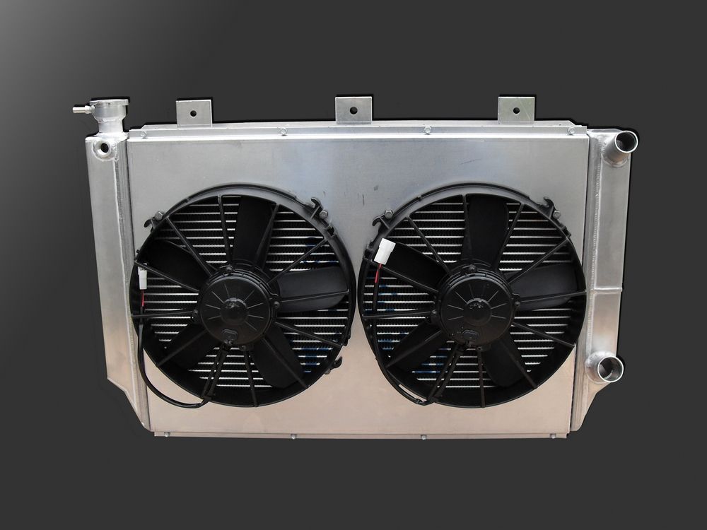
By contrast, electric fans can be very neatly packaged and integrated with the radiator and shroud. Because they aren't coupled to engine speed, electric fans can produce full airflow all the way down to idle. Quality fans like those from SPAL are rugged and reliable with sealed waterproof motors and tough plastic housings. Because they are electrically powered, electric fans can be computer controlled by the engine`s ECM or thermostatically controlled via a thermistor (a temperature sensitive switch installed in the coolant flow). Electric fans are available in a large variety of styles and sizes to fit any size or shape radiator. I like to run two smaller fans in an offroad rig simply for redundancy`s sake - that way, if one quits, you still have one operational. You don't get this choice with a mechanical fan. "Puller" style electric fans that mount behind the radiator and pull air through the radiator, as shown here, are the best choice because they are both more efficient (move more air for given fan RPM) than pusher fans, and they obviously don't block airflow from the front of the rad like a "pusher" style fan does.
|
||||||||||||||||||||||||||||||||||||||||
A fan's capability is measured in CFM, as we have noted. However, the consumer needs to be careful when shopping for a fan by rated specs. Any given measurement for a fan's CFM must be taken (and therefore should be quoted) at a given air pressure (hey - that sounds familiar - pressure and flow being related! Man - physics rocks!). Too often this information is not quoted, and you can bet that the CFM spec is therefore rated at 0PSI which is not representative of actual operating conditions. Just as important, a fan's flow spec should also include the voltage provided and amount of current drawn for each pressure/CFM rating. This is a good sober second-check of a fan's claimed capabilities. Be extremely wary of a fan that claims it pulls 3000CFM while drawing only 10amps - it's just not realistic. My Griffin radiator uses twin 305mm (12") SPAL VA01 - AP70/LL - 36A electric axial motor paddle-blade high-performance individually balanced fans with sealed waterproof motors. From the spec sheet of the fans, the pressure / flow / amps specs are as follows (note that the units in the table are metric - the fans are Italian dontcha know!):
And here is the graph, taken from this document.
Water PumpBecause cooling efficiency is directly related to coolant flow, the more flow the better, the higher the water pump's output the better. Typical small-block water pumps flow anywhere from 35-50 gallons per minute (GPM) which is sufficient for stock-like power in the 200+hp range. The "LS" series of water pumps flow about 100 GPM which is equivalent to a high-flow SBC water pump and sufficient for 5-600+ horsepower. Aftermarket pumps for many different engines are available for the harshest racing conditions that can flow up to 180+ GPM. If I were spending money on a high-performance aftermarket pump, I would make sure it came supplied with a characteristic performance curve, if only to make sure that the supplier really knows his stuff, and isn't simply marketing something with a label of "high flow" or "high performance". Because flow is king, it is not generally advisable to use an underdrive pulley (larger pulley) to slow down the water pump. The rare exception would be if you regularly run a race motor at 7000RPM or more, as this is about the max RPM that a water pump is effective at. Because of the centrifugal design, at very high speeds the water pump can cavitate and pump more air than coolant, so in this case the pump would need to be slowed down - but remember, this is only true for those running consistent high RPMs. Of course, by slowing down the pump, what you gain on the top end you loose on the bottom so at low RPM the pump will be too slow and the cooling system will suffer from inadequate flow - which isn't normally a concern for race cars that are always run at near max RPM. For everyone else, some claim that by under-driving the water pump some horsepower can be saved, and while this may be true, the small gain is usually more than offset by power loss due to higher temperatures that result from the reduced coolant flow. On the other hand, if you suspect that you are not getting all the performance you need from your cooling system you can usually safely overdrive (speed up) the water pump by 20-30% to increase flow and this can make a noticeable difference in cooling performance. The first indication of a weak or failing water pump may often be observed as a problem with the rear-most cylinders - such as a lean condition (evident in plug readings or exhaust temperatures or a pre-ignition condition). This is because the engine block and cylinder head water jackets form a manifold through which the water pump must pump the coolant. If the pump is unable to produce the required pressure or flow, the farthest point from the pump (the rear cylinders) will experience the problem first. ThermostatMy recommendation is to always use a thermostat. The reason is simple - its job is to regulate operating temperatures so that the engine warms up as quickly as possible, and then remains at the designed operating temperature. Without a thermostat, the engine may take far too long to warm up, and in some conditions may not warm up properly at all. When the engine is below operating temperature the oil's viscosity is too high to properly lubricate the engine, particularly the critical bearing clearances. Combustion efficiency (and therefore power production), emissions, and component wear also suffer. One thing to be careful of though, when designing your system and using a thermostat, is to ensure your water pump has an internal bypass circuit (refer back to #6 in the flow diagrams above). Most do, but some aftermarket high-flow racing pumps do not. For these pumps, a special thermostat with a bypass hole is used, or the user drills their own bypass holes in the thermostat (typically one to three 3/16" holes) so that the system can flow when the thermostat is closed. If you choose to run without a thermostat, do not use a restrictor. The restrictor will do nothing for you except reduce coolant flow which ultimately reduces cooling. Years ago restrictors were popular for two reasons that do not hold true today. First, as we have discussed, older radiator designs (large cross-sectional area copper tubes) were poor at promoting the necessary coolant turbulence in the radiator, so a restrictor was used to cause the coolant to begin tumbling as it exited the engine and entered the radiator. Secondly, with engines that had the thermostat located in the outlet of the engine combined with down-flow radiators that had a fairly low pressure radiator cap on the high pressure inlet side, if the thermostat was removed the increased pressure seen by the cap from the water pump could cause the cap's rating to be exceeded and the valve to open and purge coolant. Since this opening of the rad cap is what regulates system pressure, it meant that the overall system pressure would now be lower - the cap would open sooner than if the thermostat were in place holding backpressure in the cylinder head. Since system pressure was now lower, coolant vapour point was lower, and therefore the coolant's ability to effectively carry-off heat from the engine at higher temps reduced. This in turn would result in eventual overheating. Many folks erroneously assumed that the overheating was due to the coolant flowing through the radiator too quickly with the thermostat removed, that it didn't have time to cool in the rad. As a result, restrictors were used to "slow the flow of the coolant" and the car stopped overheating. Unfortunately, these folks didn't understand the real cause and effect of the overheating that they experienced after removing the thermostat, and this led to two enduring myths that persist today. What was really happening was that the removal of the thermostat didn't cause the coolant to flow too fast to cool (we know this is an impossibility), but rather caused a condition where either system pressure (and therefore coolant vapour point) was lowered or where the rad purged coolant which caused the car to overheat. The end result was the same - the car overheated - but the cause and effect were confused and so the myths that a) removing a thermostat can cause a car to overheat and b) coolant can be pumped too fast through a radiator to cool properly began. Neither of these are true. Of course, today's cross-flow radiators that locate the rad cap on the low-pressure side, do not subject the rad cap to the maximum pressure created by the water pump and so are not susceptible to the pump forcing coolant past the rad cap. We also know now that all systems benefit from maximum flow - never from reducing flow. Ultimately, reducers reduce the flow of coolant which actually hurts system cooling efficiency, not improves it. Plumbing & BleedingCoolant hoses should be as large as possible consistent with the diameter of the water pump inlet and outlets. radiator inlets and outlets should be spec'd to match. Small Block Chevys typically use a 1.5" engine outlet and a 1.75" water pump inlet. "LS" motors typically use a 1.25" water pump outlet and a 1.5" water pump inlet. Where bends are necessary, they should be large radius bends. It is a good idea to use some sort of internal support inside a hose bend to prevent the hose from collapsing and reducing or shutting off coolant flow. High quality hoses and periodic hose checks and replacement are a must. If a fairly high pressure rad cap is used, consideration should be given to double-clamping all hose connections. The higher the system pressure, the more critical hose inspection and replacement become. The use of stainless-steel braided hoses in the coolant system is actually a detriment to cooling as the outer metal braid serves to insulate the hose and trap heat inside. The use of all-metal pipe or hose is ok, as it will actually help to dissipate heat. So, all-rubber, or all-silicone, or all-metal hoses (with rubber connectors) are ok, but metal coated or sleeved rubber hoses should be avoided. In addition, stainless-steel braided hoses with AN style fittings are often sold in kits with smaller ID than the standard hoses they replace. There's nothing wrong with AN style fittings per-se, but they should only be used with careful knowledge of the ID of the fittings and hose so as to avoid unnecessarily reducing the ID of the plumbing and thereby restricting coolant flow. When filling a coolant system, either after maintenance or for the first time, there will always be some air trapped inside and it is important to bleed the system of this air. Here are some tips:
ElectrolysisElectrolysis is the name given to chemical changes that are caused by passing an electric current through an electrolyte. An electrolyte is a nonmetallic electrical conductor in which current is carried by the movement of ions. Coolant is an electrolyte. In a cooling system, the chemical change caused by electrolysis results in the stripping away of metal (aluminum ions) from the inside of the radiator. This damages and can eventually weaken and destroy the radiator. The use of dissimilar metals, particularly brass or steel with aluminum, as well as contaminates and corrosion in the coolant and the use of water with high trace elements all contribute to or compound the harmful effects of electrolysis. To prevent electrolysis and corrosion from damaging your cooling system you must:
The source of harmful electrical current passing through the coolant can either be from the circuits of poorly grounded vehicle electrical components seeking ground (in which case the current will be DC) or from static electricity developed in the drivetrain components (transmission, transfer case, and axle differentials) seeking ground (in which case the current will be AC). Both are harmful. Methods to eliminate current in the coolant and therefore electrolysis include:
In order to test for electrolysis, it is necessary to use a multi-meter to check for voltage in the coolant. The procedure is as follows: To test for DC voltage:
If you detect DC voltage in the coolant using the above test, you will need to repeat the test as you systematically switch off electrical systems one by one in order to isolate the circuit that is at fault. Once the circuit is isolated, you must correct the improper grounding situation in that circuit. There is no real practical way to test for AC voltage generated by static electricity, unless you have access to a chassis dyno. Grounding each of the drivetrain components is a good preventative step. Finally, if you detected current in the coolant, after correcting the electrical problem, always change the coolant as it will have been damaged by the current. MythsIf we're going to tackle persistant myths, there's no better place to start than the following piece, written by Bob Weber of Ebb's Speed Shop. It's a well written piece and absolutely hits the mark. Reproduced here with permission...thanks Bob!
To understand fully, we have to put our rad back into the whole system where coolant is flowing and consider the effects of flow rate on the system as a whole. Slowing the coolant in the rad may allow that coolant (the coolant in the rad) to dissipate a little more heat (but not much), and at an ever decreasing rate (exponentially decreasing) BUT since the cooling system is a closed-loop system, you also have to consider what’s happening outside the radiator if you slow the flow - especially to the coolant in the engine. If you slow the coolant through the rad, you slow the coolant through the engine too. And this coolant is subject to the same laws - the greater the initial temperature difference between the engine and the coolant, the greater the rate at which the coolant absorbs the heat from the engine. BUT - if we leave the coolant in contact with the engine for longer by slowing the flow through the rad, the delta-T between engine and coolant decreases and with it the rate at which the coolant in the engine absorbs the heat from the engine. Meanwhile the engine is banging away producing heat, but the coolant is absorbing it at a slower and slower rate - that heat has to go somewhere, and since the slow coolant is becoming less efficient at absorbing it - it stays in the metal - and the metal overheats! Meanwhile, back at the rad, you're wasting time trying to shed the last little bit of heat when the delta is small instead of carrying away the “big chunks” of heat. And the situation just gets worse and worse in a downward spiral. Imagine emptying a truckload of sand using a small wide-mouth container vs. a larger narrow-mouth container. The job will get done quicker by making more trips with the smaller container that takes less time to fill and empty, rather than taking the time to fill the larger narrow-mouth container and then taking the time to empty it – that extra in the larger narrow-mouth container isn’t worth it – better to dump the load and go back for more. Or, how about this for those who are fans of elaborate metaphorsImagine a circular train track with two stations opposite each other and rail cars that fill the whole track. One station has an endless supply of passengers trying to get on and the other is where they get off and disperse. Your job as the train driver is to move as many people as possible to keep them from accumulating at the embarkation station and crushing each other. Now imagine the passenger cars are funnel-shaped on the inside. This means the first big batch of people can get on and off quickly, but completely filling the car takes a lot longer as people have to squeeze into the narrower portion.
You could drive the train fast, quickly loading and unloading the big, easy-to-fill, portion of each car, forget about the smaller portion, and keep picking up and dumping off a large group of passengers as fast as you can. In fact – the faster you go, the better…the more efficient at moving large numbers of people the system will be. Screw the last stragglers – they’re insignificant and won’t help you – just move the big chunk and move on, going back for more, more often. So – you want high flow / high (turbulent) speed so it picks up and dumps off the most heat quickly – it’s inefficient to try and shed the last little bit of heat when the delta is small, and can lead to overheating because you’re wasting time not carrying away the “big chunks” of heat. Griffin Thermal Products "King of the Hammers" Rad ReviewNow that you are all cooling system experts - you are finally ready to see and appreciate the awesomeness of the best offroad radiator money can buy - the: Griffin Thermal Products "King of the Hammers" Radiator For those that may be unfamiliar, the name is taken from the name of the toughest, most gruelling one-day off-road race in the world - the King of the Hammers (KOH). You can learn more about the race at the official KOH website. Suffice to say, the race is absolutely brutal on equipment, notably cooling systems, and the Griffin KOH rad was specifically designed and developed to cool offroad race rigs under the brutal onslaught of hour after hour of combined desert racing and tortuous rock crawling! In short - it is one hell of a radiator built for the toughest job a radiator can be asked to do - here's a look: The first thing you need to know is that Griffin is a true manufacturer. Almost anyone can buy components and assemble a radiator, and the truth is that a lot of so-called "manufacturers" do just that. Griffin is an integrated manufacturer. They make the tubes, fins, headers, side bands, mounting brackets and tanks. By controlling every step of the manufacturing process, they produce a radiator with components that are performance matched for optimum cooling capability. A Griffin is more than some off-the-shelf, one-size-fits-all, cookie cutter product. It is a performance radiator made to meet the customer's specific application. The other thing you need to know is that Griffin manufacture a huge range of radiators to suit many needs and applications - from budget replacement models to custom race radiators like the one I'm about to show you. As such, after reading and digesting this article, the first thing you need to do is call and speak to the appropriate expert about your needs and application. To talk off-road applications and about the KOH rad, call Vice President Tom Beebe and / or Off-Road Sales Tech Benji Durham who are both reachable at 1-800-RACERAD and 1-864-845-5000. Tell them I sent you and they will take care of your questions and needs. After speaking to them, if you decide to have a KOH off-road race radiator custom built for you like I did, the first thing you need to do is provide them with a diagram of what you need. They told me they accept everything from full CAD drawings to doodles on the back of a bar napkin - but obviously the better your diagram the more quickly they will be able to produce your radiator. That's because, after deciphering your diagram, the first thing they will do is send you a proper engineering diagram of what you have requested for your approval. Only after you have approved, signed, and returned the diagram will they build your custom unit. I ended up humming and hawing over options and what I wanted and we sent the diagram back and forth a few times as they made the changes I requested each time I changed my mind or thought of something else. Never once did they loose patience with me. |
|||||||||||||||||||||||||||||||||||||||||
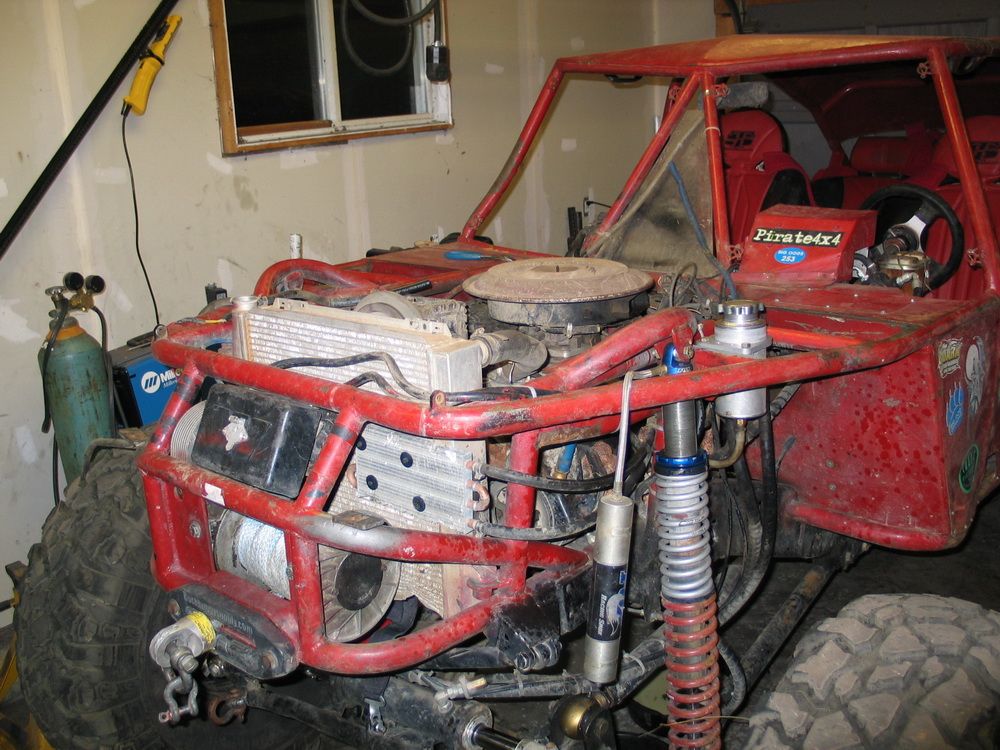 |
This was my old setup with a puny 28x16 rad. Not only was it not going to cool the new LS2, but looking back it wasn't really the prettiest looking front end either. As I mentioned earlier, after some head scratching I decided that, instead of fitting the biggest rad I could, I would re-do the front end to fit the rad I wanted - which was approx. 31"x19". |
||||||||||||||||||||||||||||||||||||||||
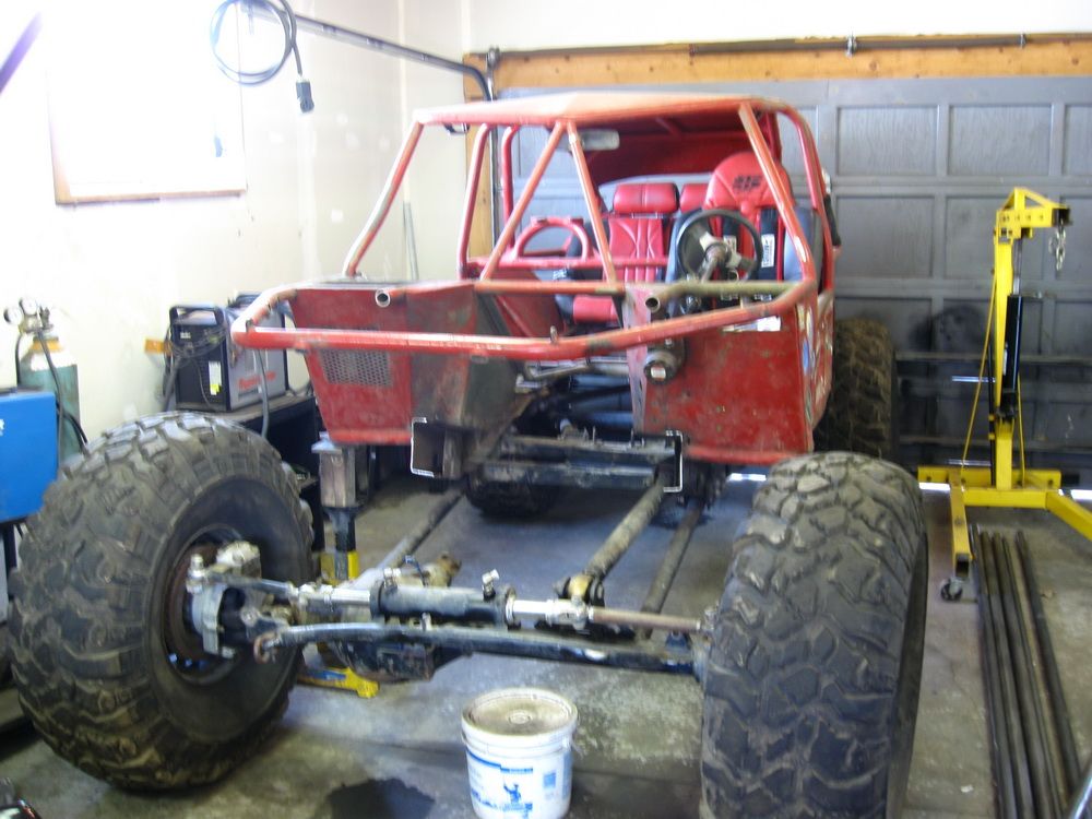 |
I wasn't kidding when I said I cut the whole front end off... | ||||||||||||||||||||||||||||||||||||||||
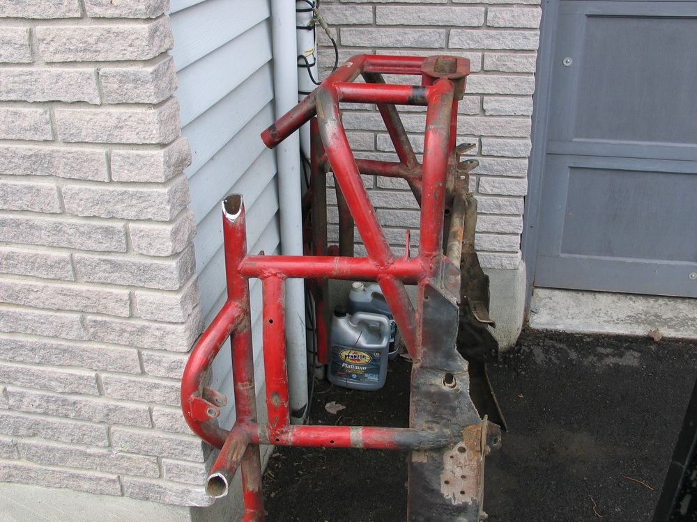 |
... not kidding at all! | ||||||||||||||||||||||||||||||||||||||||
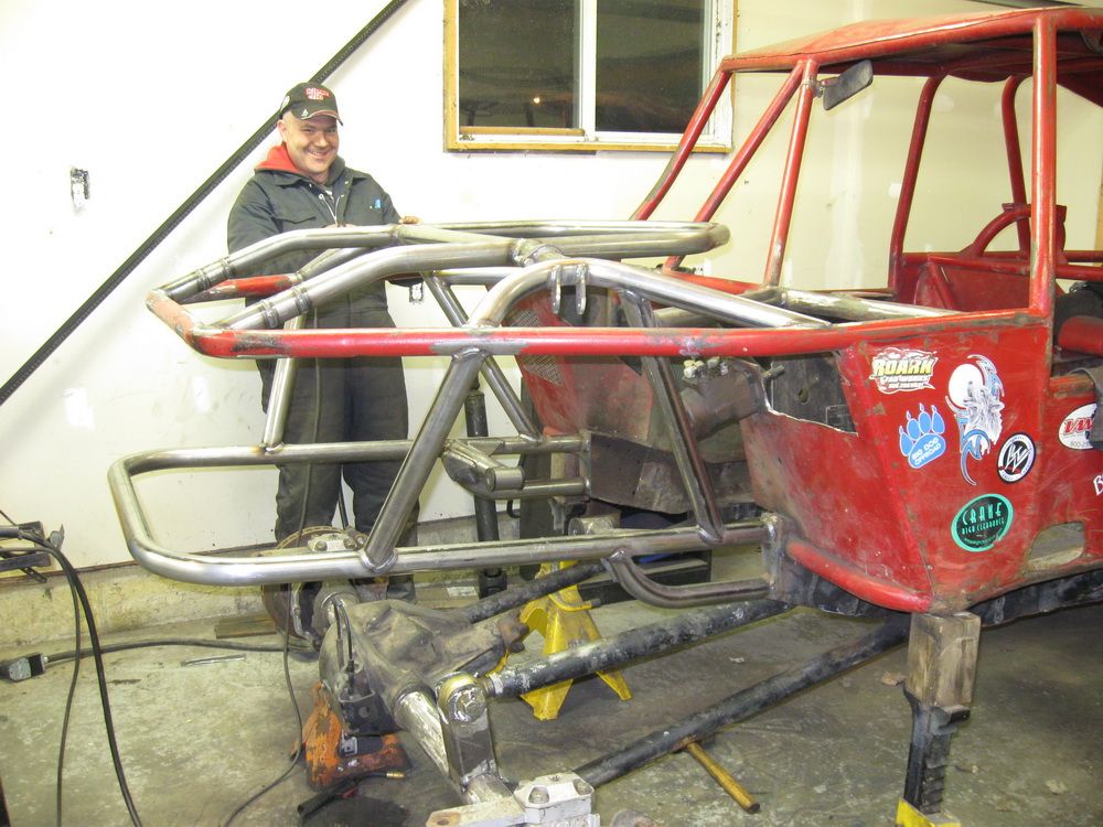 |
First came the basic re-design to fit the size I wanted. And it looks like I was enjoying myself back then - you know - the way you do at the beginning of a project! |
||||||||||||||||||||||||||||||||||||||||
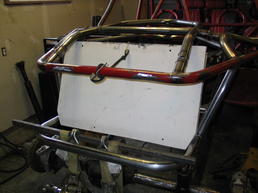 |
Then, before making and sending my initial drawing to Griffin, I did a bunch of test fitting with a drywall-and-2x4 mock up to get the exact dimensions I wanted so that the rad would tuck nicely into the chassis. | ||||||||||||||||||||||||||||||||||||||||
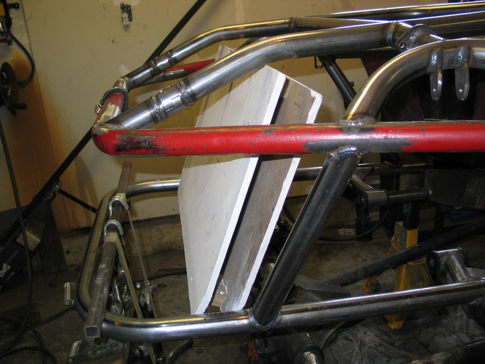 |
A couple of 2x4 blocks were used to hold two pieces of drywall apart at the right distance to simulate a 3" thick radiator. | ||||||||||||||||||||||||||||||||||||||||
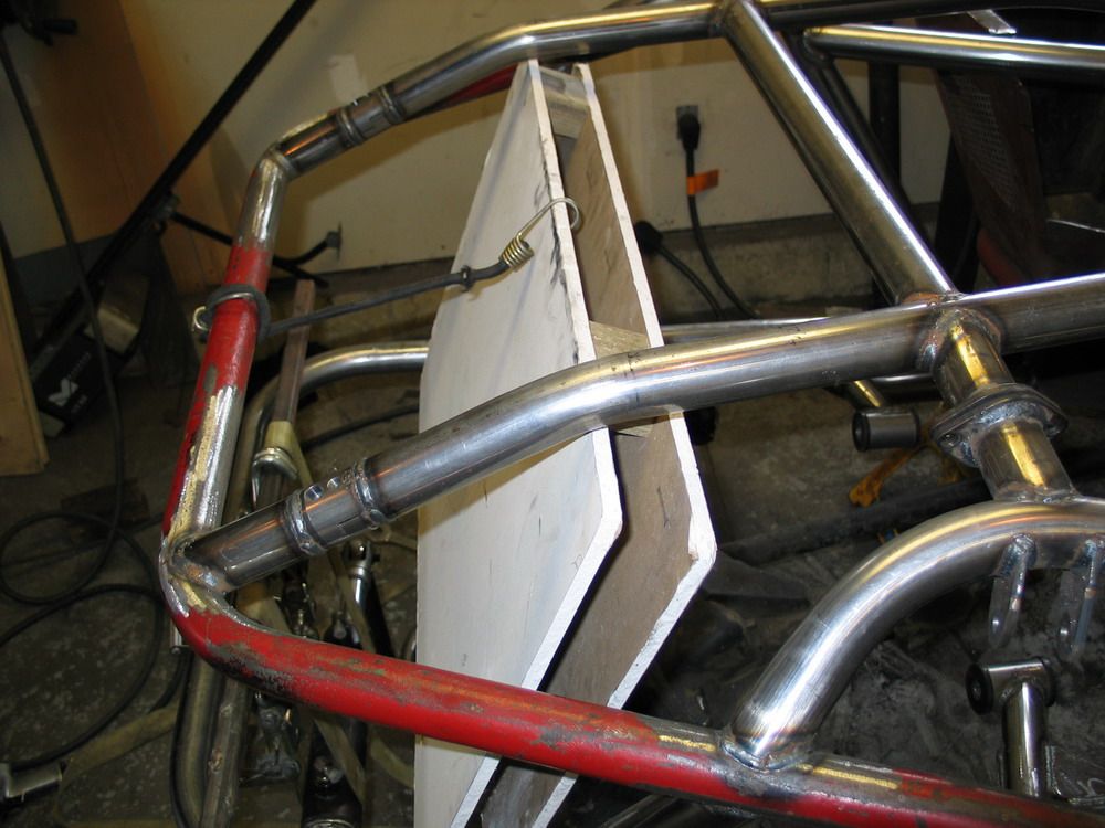 |
I knew I wanted to lay the rad back a little, to prevent it from sticking way up in front. But not so much as to induce flow problems. I settled on about 20°, and the top engine cover cradle was bent to clear the mock-up rad at the right angle. Now I was committed! |
||||||||||||||||||||||||||||||||||||||||
 |
To get the height and angle exactly where I wanted them while maintaining as large a surface area as possible... | ||||||||||||||||||||||||||||||||||||||||
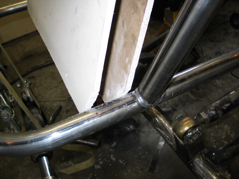 |
... the lower end of the tanks would have to be notched to fit between the frame rails. At this point I was sure hoping that Griffin hadn't overstated it when they said they could build anything I could draw! |
||||||||||||||||||||||||||||||||||||||||
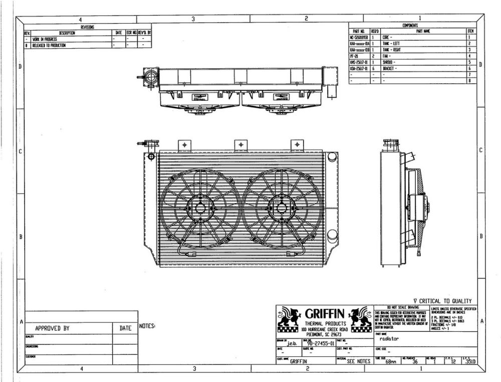 |
After sending them my chicken-scratch drawing, they produced the engineering diagram and we sent it back and forth a few times as the details were finalized. Here is my final approved diagram. And they hadn't overstated anything - sure enough they were going to build me my rad exactly as I had wanted! Note: Some detail and the dimensions have been removed from the diagram at left to prevent unscrupulous entities from knocking-off Griffin's products. The actual diagram you get is full-blown engineering diagram with all the dimensions. |
||||||||||||||||||||||||||||||||||||||||
With the diagram approved - Griffin set about building my rad. Here's a look behind the scenes: |
|||||||||||||||||||||||||||||||||||||||||
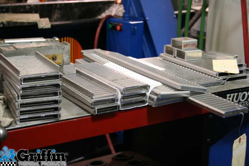 |
Here are the CNC'd headers. | ||||||||||||||||||||||||||||||||||||||||
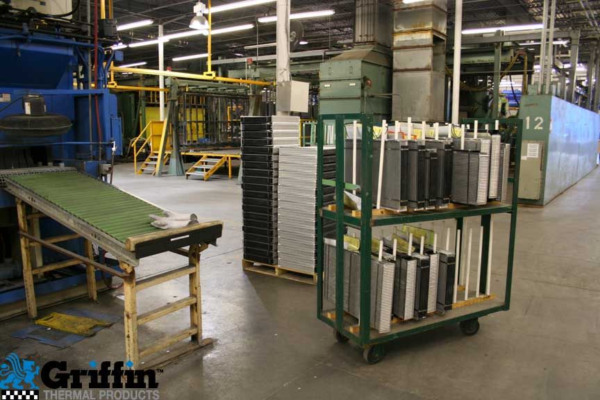 |
Here is the core assembled, post washer, and just before going into the braze oven where it will be vacuum brazed with a magnesium based cladding. | ||||||||||||||||||||||||||||||||||||||||
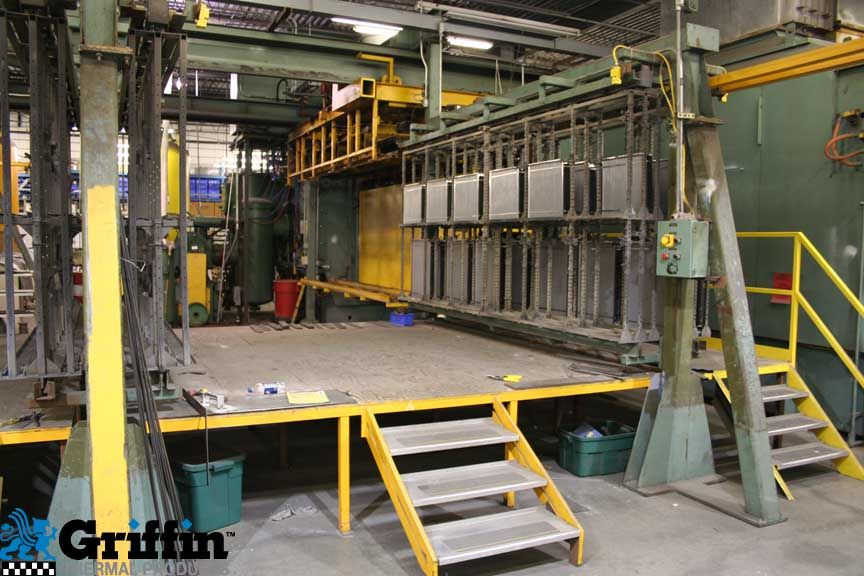 |
Here's the core heading into the 1200°F braze oven. | ||||||||||||||||||||||||||||||||||||||||
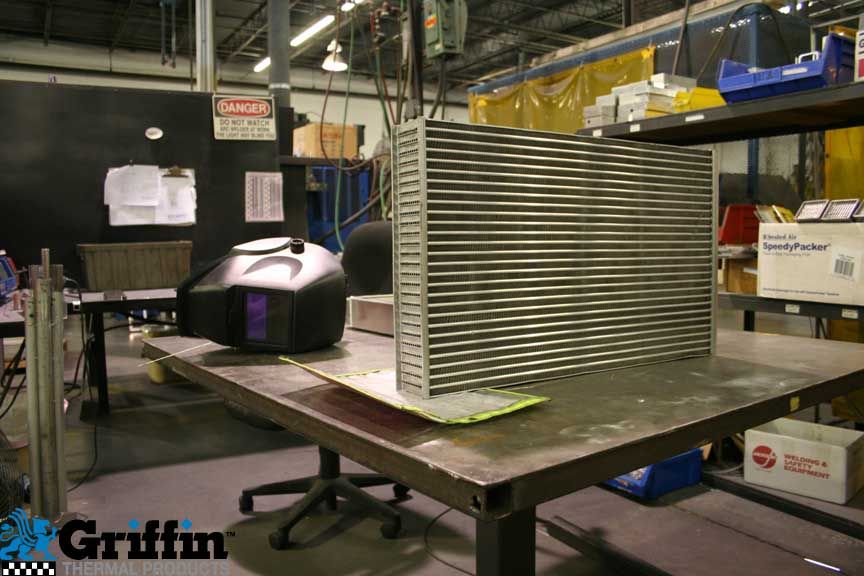 |
Here's the core after the braze oven, completed and ready to have the tanks TIG welded on. | ||||||||||||||||||||||||||||||||||||||||
 |
Here are the raw materials used for the C-channel tanks. | ||||||||||||||||||||||||||||||||||||||||
 |
Here the radiator is being TIG welded together. The radiator tank material for the KOH radiator is 0.125" thick. |
||||||||||||||||||||||||||||||||||||||||
Here's an interesting tech tidbit that you wouldn't know from reading most other manufacturers marketing material. A lot of so-called manufacturers (most of whom are actually just "assemblers") like to make a big deal about not using any epoxy in their construction. The thinly-veiled insinuation is that those who do are somehow using an inferior process to "glue" the radiator together. If you don't know any better, they make it sound as if the mere mention of epoxy signals some cheap throw-away product. What they don't bother explaining is what epoxy use is really about. So here's a little useful tech on the subject. First, Griffin’s core is always welded to the tank. Griffin does not use any glue in the manufacturing process. Second, at Griffin, epoxy is a secondary process applied to some radiators to increase durability. All Griffin radiators are vacuum brazed with a magnesium based cladding. The purpose of the epoxy is to relieve the shear stress on the tube-to-header braze joint to ensure a long leak free life for radiators used in extreme conditions. The common misconception is that epoxy is used to “glue” radiators together. Some manufacturer's may do this, but Griffin does not. And remember, because they make so many different types of radiators for so many different applications from race cars to locomotives to aircraft, and because they manufacture everything from scratch in-house, they use many different designs and techniques, depending on the product in question, and not all use epoxy. In fact, my KOH radiator does not use any epoxy at all in its construction - I'm just making a meal out of this issue because it's a perfect example of the type of misinformation contained in marketing hype passed off as "tech" by so many companies that ticks me off so much it's one of the reasons I got started in writing tech articles in the first place many years ago. Phew - I feel better now! |
|||||||||||||||||||||||||||||||||||||||||
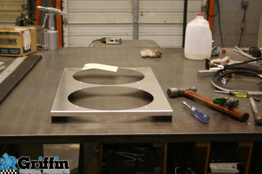 |
And here is the shroud that has been punched and formed and is waiting for the the addition of fans, followed by installation on the radiator. |
||||||||||||||||||||||||||||||||||||||||
 |
A short time later, this giant box arrived in my driveway. | ||||||||||||||||||||||||||||||||||||||||
 |
Inside was a very carefully packed radiator, some instruction sheets, and a rad cap taped to the inside of the box. | ||||||||||||||||||||||||||||||||||||||||
 |
Rad cap. | ||||||||||||||||||||||||||||||||||||||||
 |
The rad cap is a cool blue colour stamped with the Griffin logo. | ||||||||||||||||||||||||||||||||||||||||
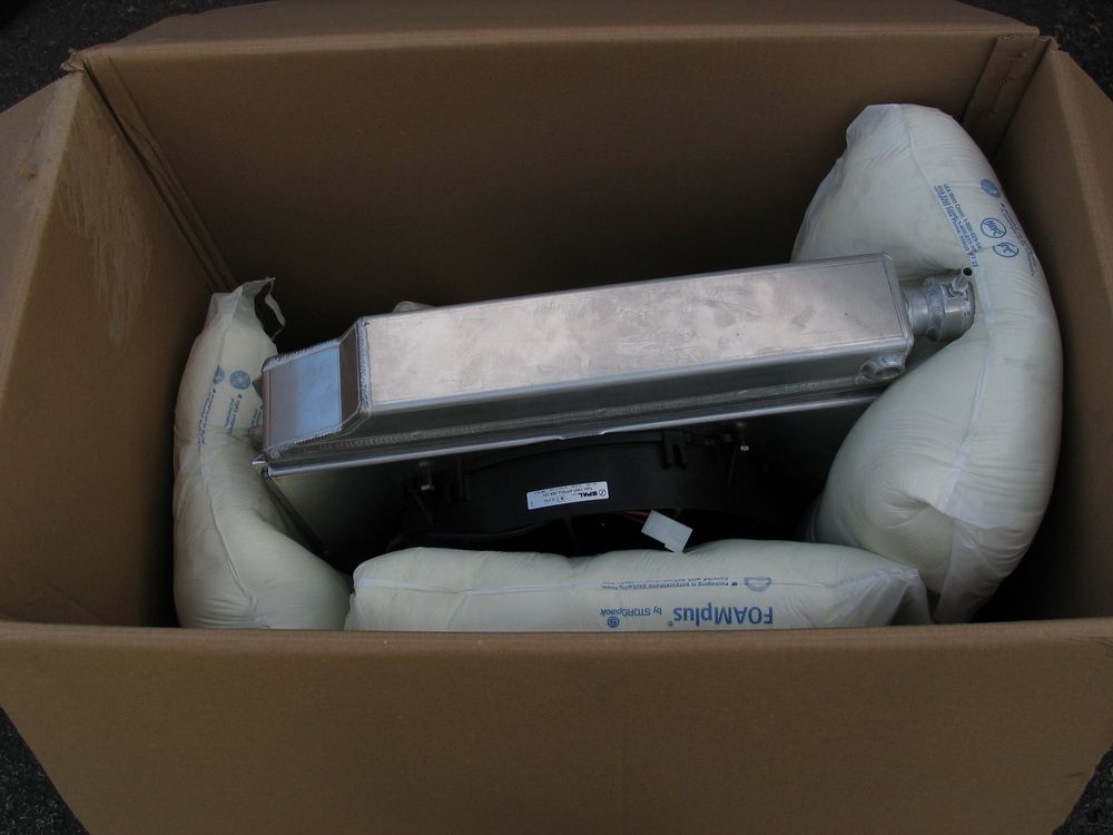 |
The radiator was well protected for its journey. | ||||||||||||||||||||||||||||||||||||||||
 |
Before I even got it out of the box I started snapping pictures of the awesome build quality. This is the notch in the tanks I requested to clear the lower frame rails. |
||||||||||||||||||||||||||||||||||||||||
 |
The quality was evident immediately. | ||||||||||||||||||||||||||||||||||||||||
 |
And everything, including the location of the filler neck and the orientation of the overflow tube was exactly as I has spec'd. | ||||||||||||||||||||||||||||||||||||||||
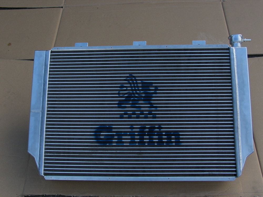 |
Out of the box at last, it was an awesome piece. Here are the details:
|
||||||||||||||||||||||||||||||||||||||||
Here's a detailed look: |
|||||||||||||||||||||||||||||||||||||||||
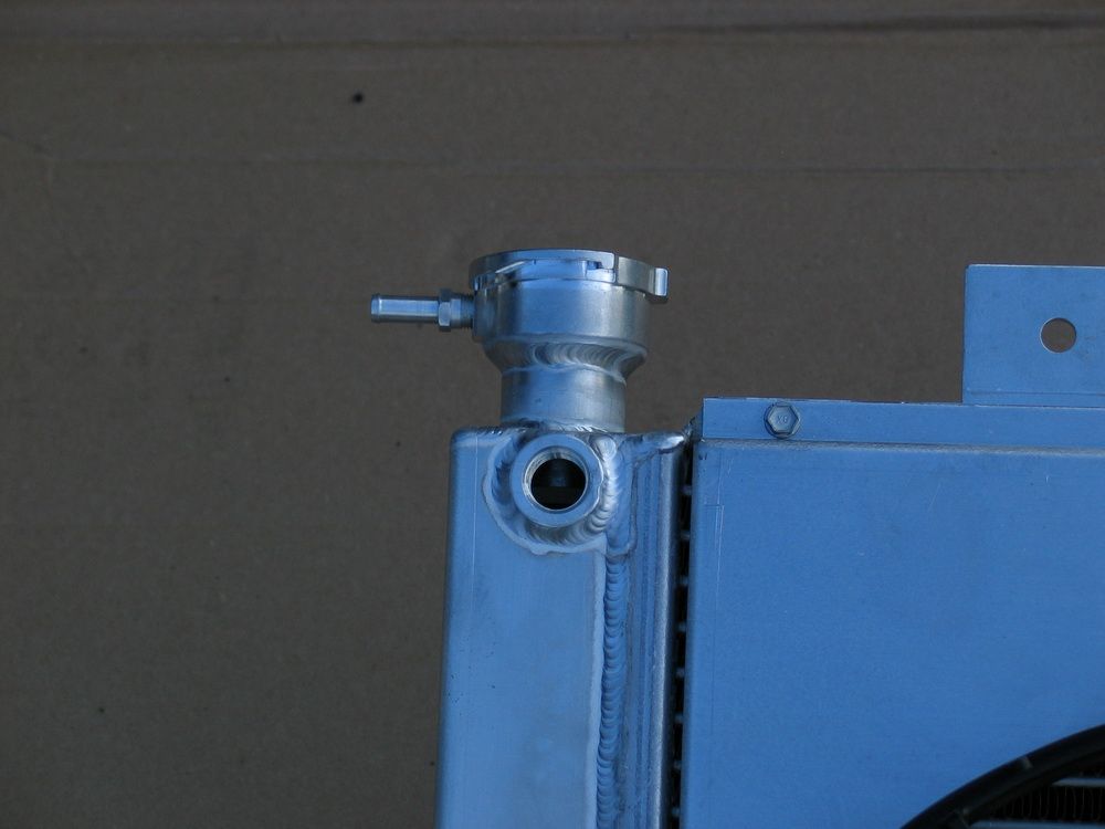 |
Filler neck on left-side tank. 3/8" NPT port to which I will connect my LS2 steam tubes. The port is larger than needed for connecting the steam tubes, but I chose this size so that I can convert from an overflow tank-only setup to a surge tank setup later if I need to. The 3/8" port is large enough to be plumbed to the surge tank. Of course, I would need to cap off the filler neck too. I'll be honest - the only reason I didn't plan on a surge-tank setup from the outset is that my front-end re-design didn't make allowances for the room needed to mount a surge tank, and that only because, at the time I did the design, I didn't yet fully understand all the benefits of a surge-tank setup. If I were to start over, I would plan a surge tank from the outset - but at least I had the foresight to order a large enough port to support a surge tank in the future. |
||||||||||||||||||||||||||||||||||||||||
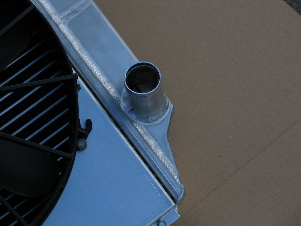 |
1.5" radiator outlet on lower right tank. | ||||||||||||||||||||||||||||||||||||||||
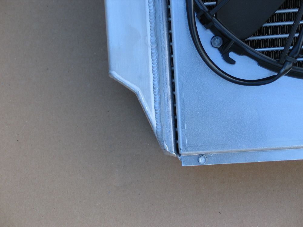 |
Custom notch to clear tubular frame rails. | ||||||||||||||||||||||||||||||||||||||||
 |
1.25" radiator inlet on upper right tank. | ||||||||||||||||||||||||||||||||||||||||
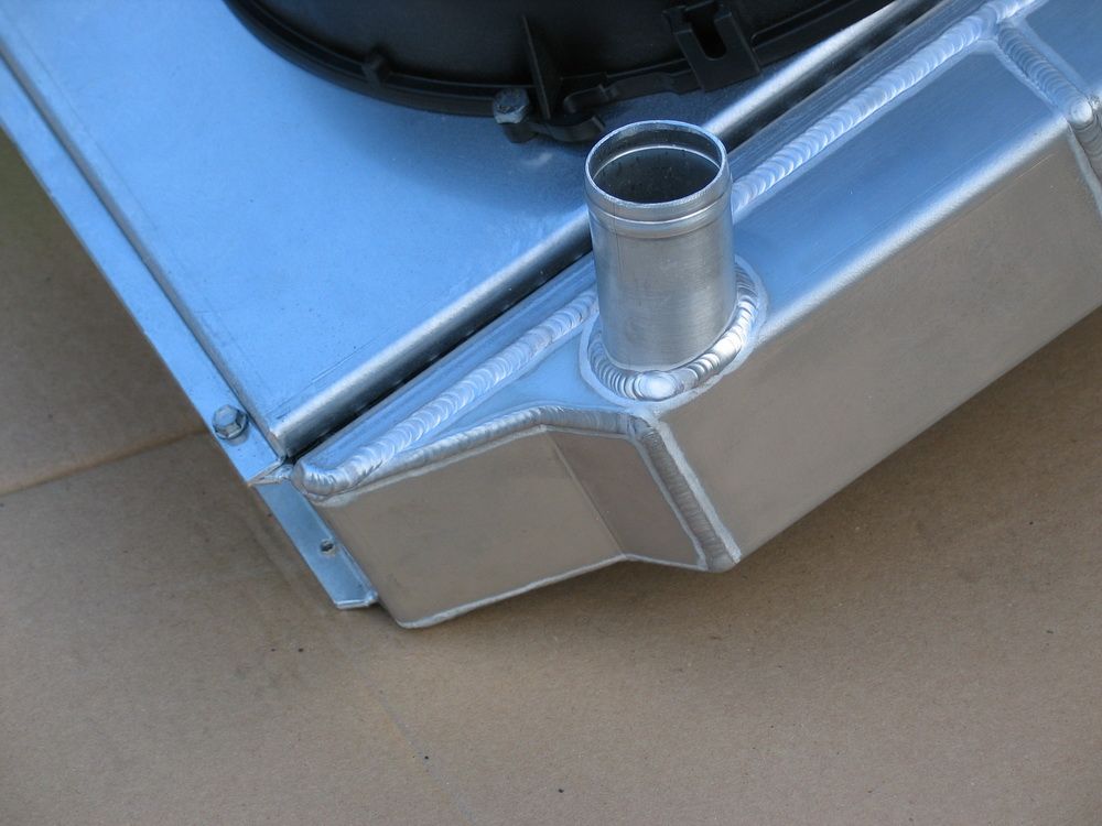 |
Notch and outlet. | ||||||||||||||||||||||||||||||||||||||||
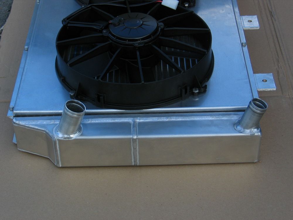 |
I ordered the inlet and outlet to be installed at an angle, so that they would be level (horizontal) with the rad installed in the chassis and leaned back 20°. Griffin were happy to oblige. |
||||||||||||||||||||||||||||||||||||||||
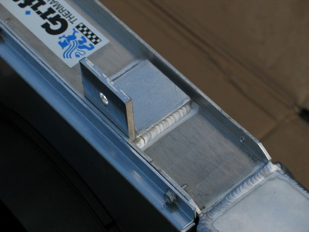 |
Aluminum mounting bracket welded to upper channel. | ||||||||||||||||||||||||||||||||||||||||
|
Filler neck. | ||||||||||||||||||||||||||||||||||||||||
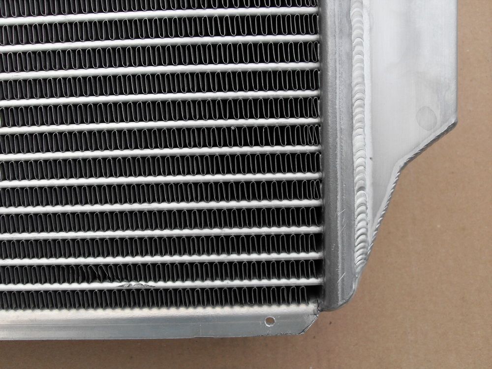 |
These are no ordinary tubes. They are constructed using the latest aluminum extrusion technology, for added flow, cooling, strength, and overall durability. Inside, where you can't see, they are ported to enhance fluid turbulation. It's a patented design they asked me not to photograph, but I can tell you it's damn cool! Also note the 12 fins per inch design. |
||||||||||||||||||||||||||||||||||||||||
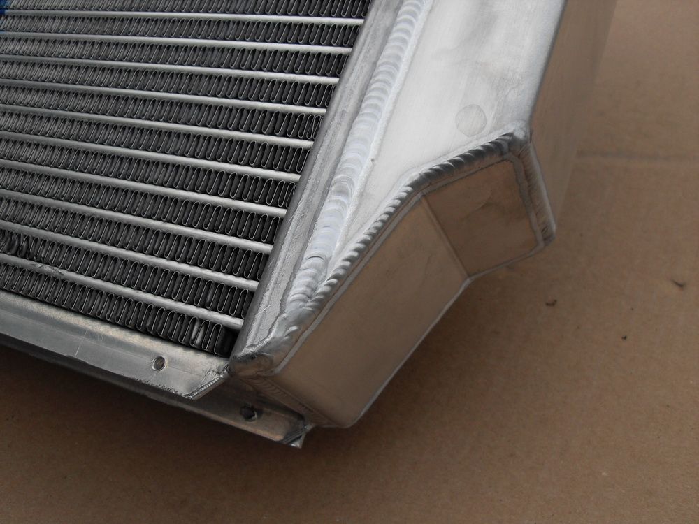 |
Extruded tubing is the newest and most exciting thing to happen in the cooling world, especially for off-road use. As an example, these new extrusions are so superior to older-style tubes that a single row of tube is equivalent to two older-style rows of tubes, and is much more durable and ridged for all of the hard hits off-road use can dish out. My KOH radiator uses single rows of 68mm extruded aluminum tubes for maximum cooling performance. |
||||||||||||||||||||||||||||||||||||||||
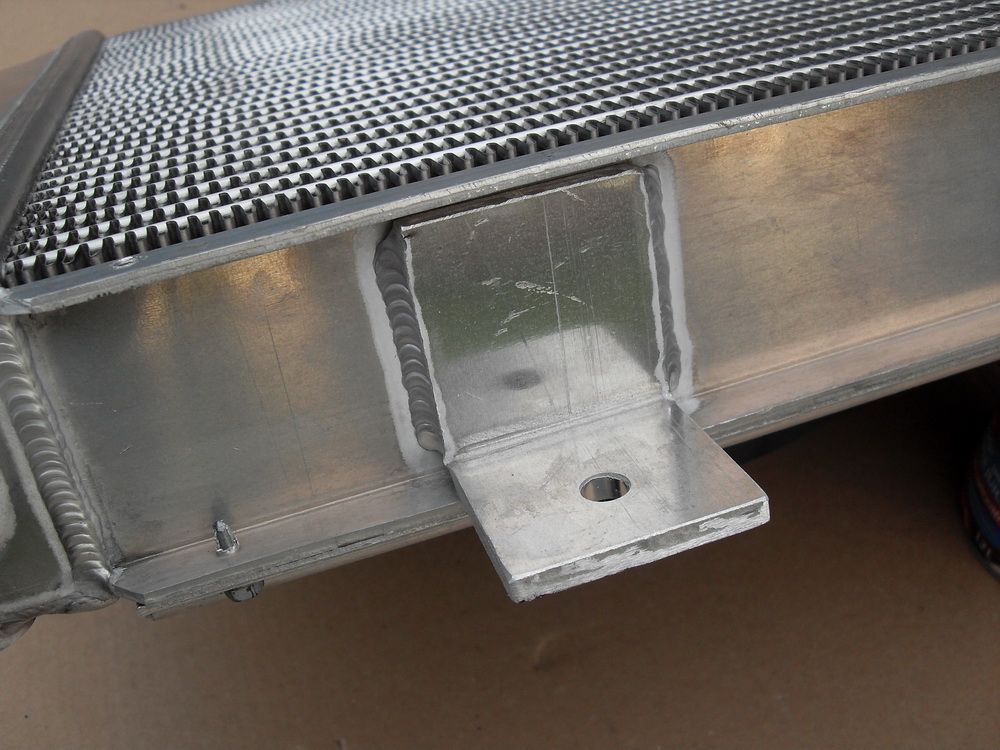 |
Another shot of one of the upper mounting brackets. | ||||||||||||||||||||||||||||||||||||||||
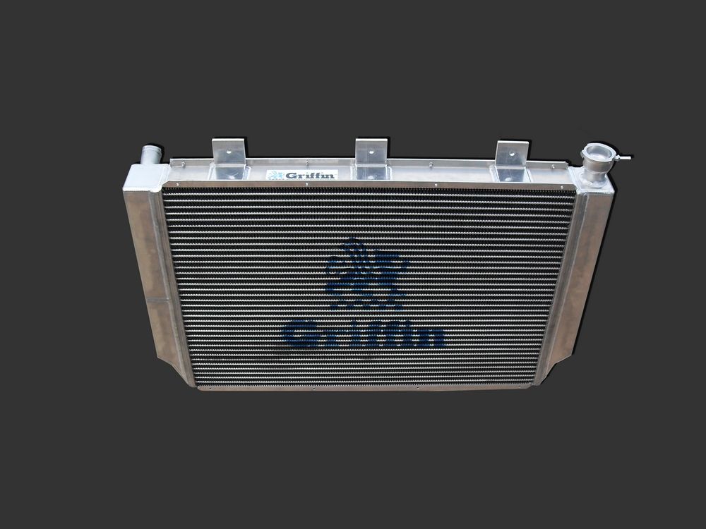 |
Top-front view of the complete rad. | ||||||||||||||||||||||||||||||||||||||||
|
Front view. | ||||||||||||||||||||||||||||||||||||||||
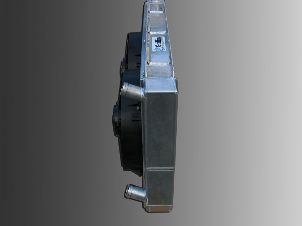 |
Side view. The rad is 3" thick. With the shroud and fans it is a total of 7.76" thick. |
||||||||||||||||||||||||||||||||||||||||
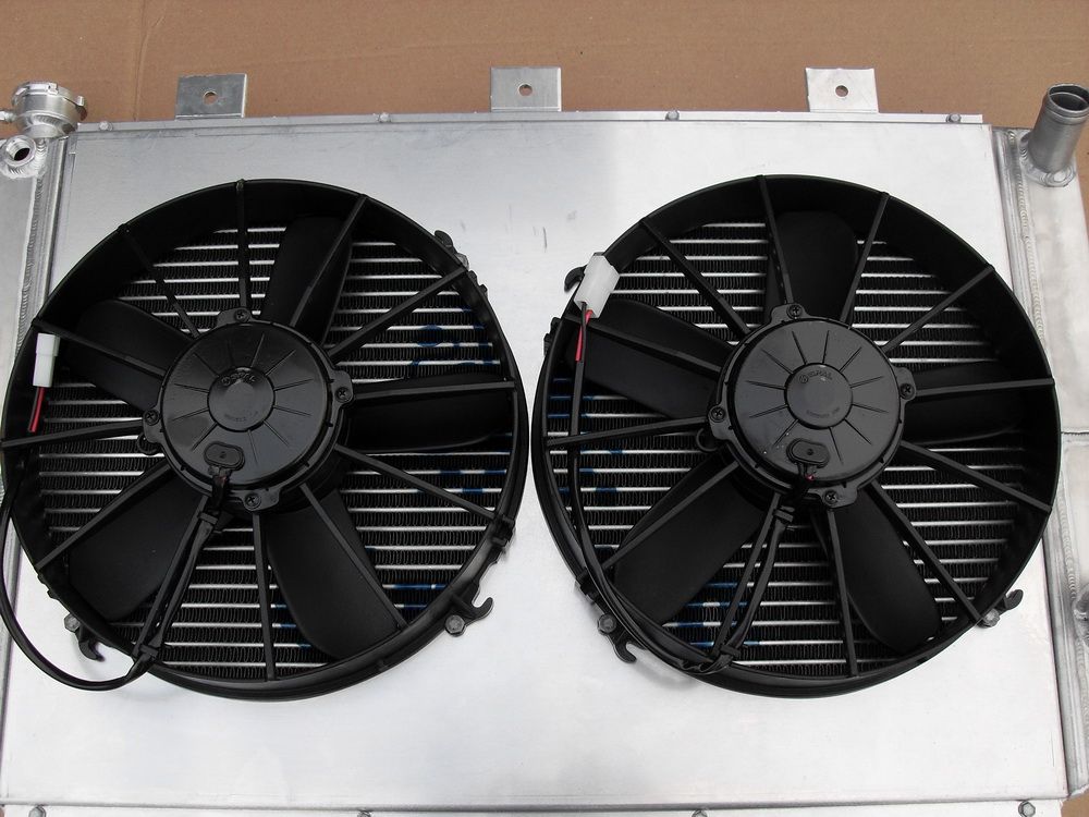 |
The fans are
twin 305mm (12") SPAL VA01 - AP70/LL - 36A electric axial motor paddle-blade high-performance individually balanced units with sealed waterproof motors.
The complete spec sheet for the fans reveal that, combined, they pull 3280 CFM. |
||||||||||||||||||||||||||||||||||||||||
Here's the complete flow chart, taken from the spec sheet and converted to Imperial units.
|
|||||||||||||||||||||||||||||||||||||||||
|
As an example of why it pays to deal with the experts at Griffin, and why when they say they build to suit your application it isn't just some marketing drivel, is the fact that I originally asked for larger fans that were rated at even higher CFM. Griffin persuaded me that this would not be the best option, as this particular model of fan from SPAL is much more rugged than the model I had originally asked for, and is far better suited to operating in the punishing offroad environment. It's nice when experts take the time to keep you from making a mistake instead of just selling you whatever. |
||||||||||||||||||||||||||||||||||||||||
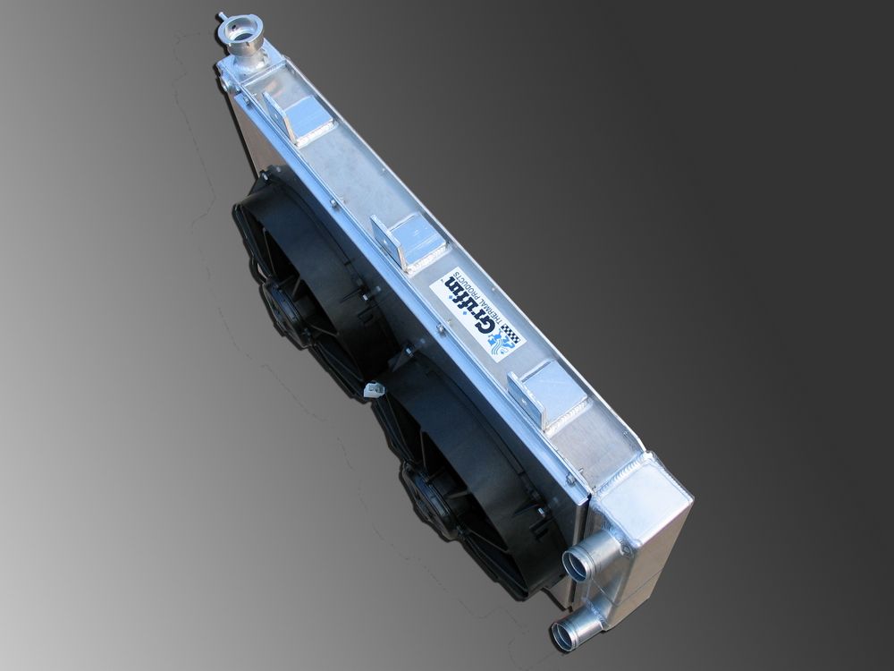 |
SPAL have this to say about the VA01 - AP70/LL - 36A
|
||||||||||||||||||||||||||||||||||||||||
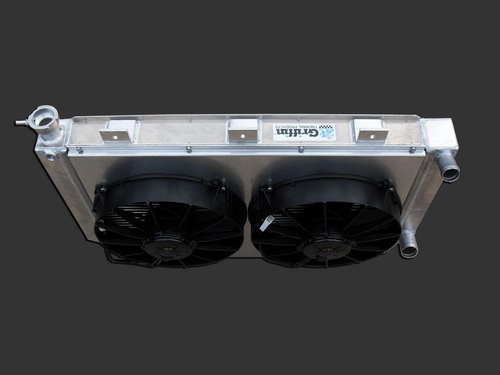 |
In addition, Griffin explained that they are recommended for offroad use due to the rugged design. They will not deflect under the shock as much as the other fans. These fans are also very close in performance to the larger fans due their larger motors and aggressive blade pitch but they are better suited to the harsh offroad environment. I will be controlling the fans via the MEFI-4 marine fuel injection ECU that came with my Turn Key Engine Supply LS2 as it is already equipped to control dual electric fans. |
||||||||||||||||||||||||||||||||||||||||
The following gallery of pics should allow you to come as close as possible to appreciating the quality and craftsmanship evident in the Griffin KOH radiator. When you're done lookin' - go order your own - you WILL NOT be disappointed!
|
|||||||||||||||||||||||||||||||||||||||||
Mounting the RadiatorThere are a great many ways to mount a radiator - pin, threaded boss, tab, clevis, bracket, saddle. Whichever you choose, one thing is constant - the radiator must be isolated in some way from the chassis using some form of rubber, urethane, or other pliable bushing material. This is particularly true in offroad application where vibration and chassis flex are unavoidable. Failure to isolate the radiator in this manner will eventually lead to failure - it's not a question of "if", but "when". In my opinion, the best way to mount a radiator in an off-road chassis is with a lower cradle- or saddle-type mount. The saddle should either be full-length to support the entire rad, or at least under the tanks as they are the heaviest and strongest parts of the rad - never just under the core. Here's a look at how I mounted my Griffin KOH radiator. I don't claim that this is the best mounting ever, but it should give you some ideas as well as illustrate the strength and support afforded by a lower saddle-type mount. |
|||||||||||||||||||||||||||||||||||||||||
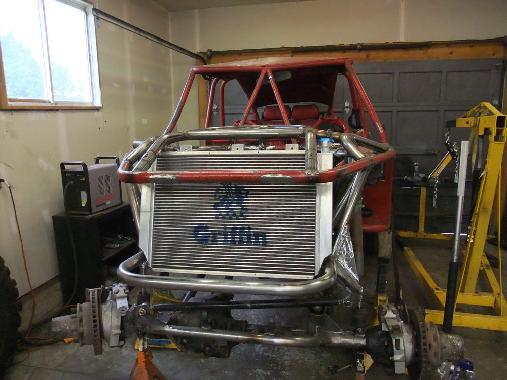 |
Early mock-up of mounting location with real radiator. | ||||||||||||||||||||||||||||||||||||||||
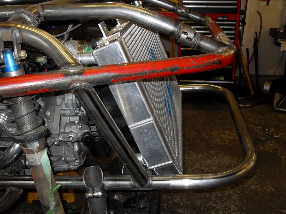 |
This shot nicely shows the purpose of the notched tanks. | ||||||||||||||||||||||||||||||||||||||||
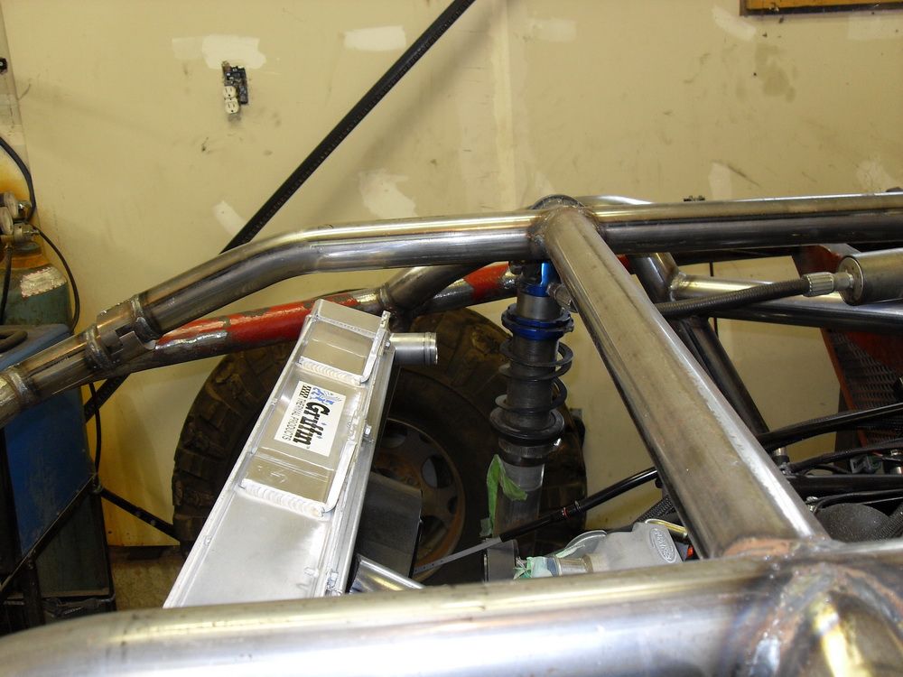 |
Notice how the radiator inlet is horizontal with the rad leaned back - that's why I asked that the inlets be welded to the tank at an angle. | ||||||||||||||||||||||||||||||||||||||||
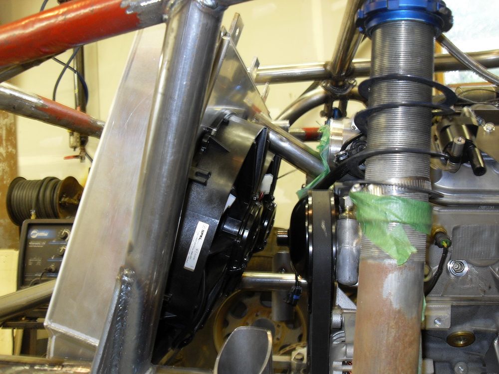 |
Checking back-side clearance. | ||||||||||||||||||||||||||||||||||||||||
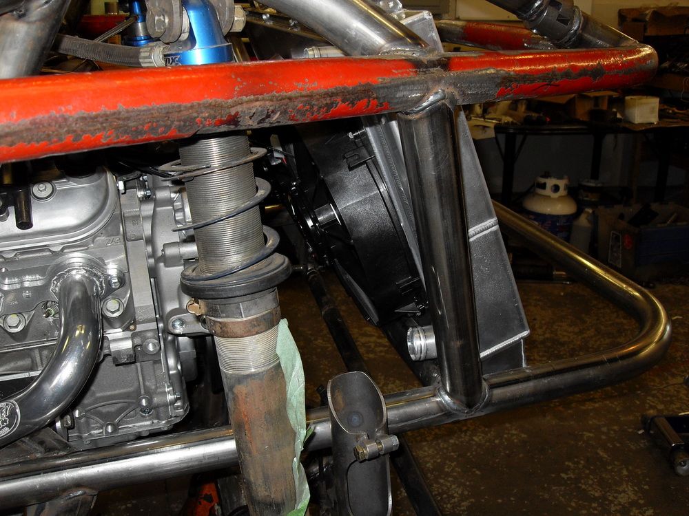 |
Right side showing radiator outlet just inside chassis members. | ||||||||||||||||||||||||||||||||||||||||
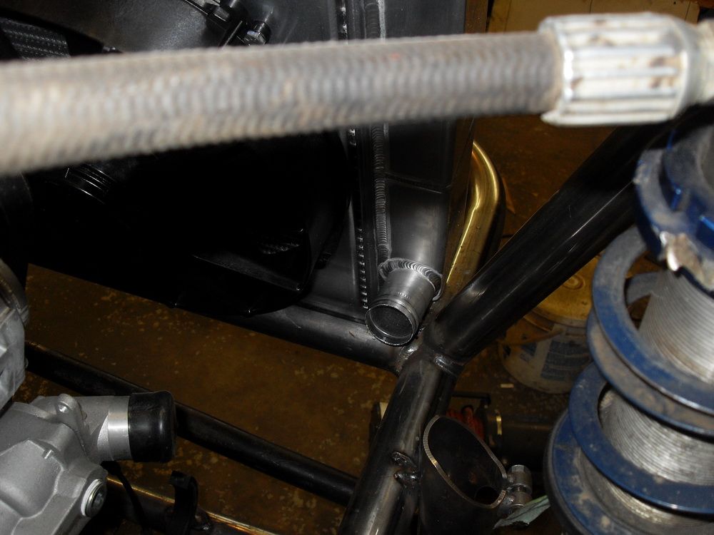 |
The radiator outlet tucks perfectly where I wanted it! | ||||||||||||||||||||||||||||||||||||||||
 |
I knew I wanted a saddle-mount, but I couldn't find any commercially available isolators or bushings that would fit my rad and chassis in the way I wanted, so I set out to make my own. I ended up using some Chevy 4x4 truck transmission mounts, cut in half. With a little work on the band saw, I had them notched to fit perfectly under the lower channel of the rad. Top is the stock tranny mount. Below are the two halves of one cut in half - unmodified on the left and cut to fit on the right. |
||||||||||||||||||||||||||||||||||||||||
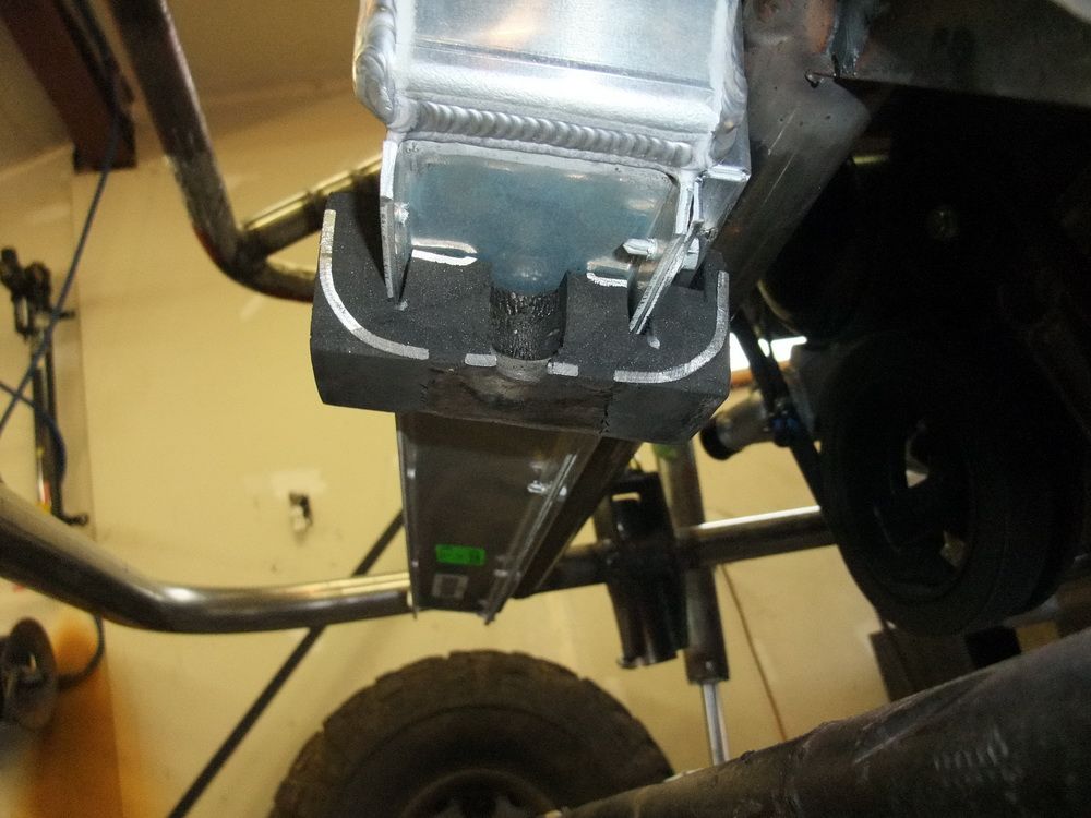 |
How the isolator fits to the bottom of the rad. I felt they were large and rugged, provided the necessary isolation, and the impregnated steel lent a certain amount of structural rigidity. |
||||||||||||||||||||||||||||||||||||||||
 |
I spaced the isolators on the lower channel of the rad where they didn't interfere with the shroud mounting on the back side of the rad. | ||||||||||||||||||||||||||||||||||||||||
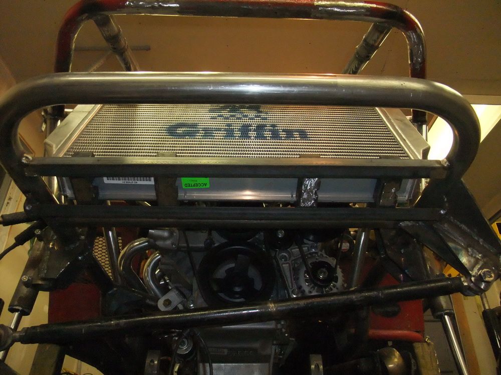 |
By using an "open" style mounting tray and separate isolators, I won't trap sand, mud, and gravel between the aluminum radiator and the steel tray which could otherwise lead to corrosion buildup and abrasion of the aluminum radiator. | ||||||||||||||||||||||||||||||||||||||||
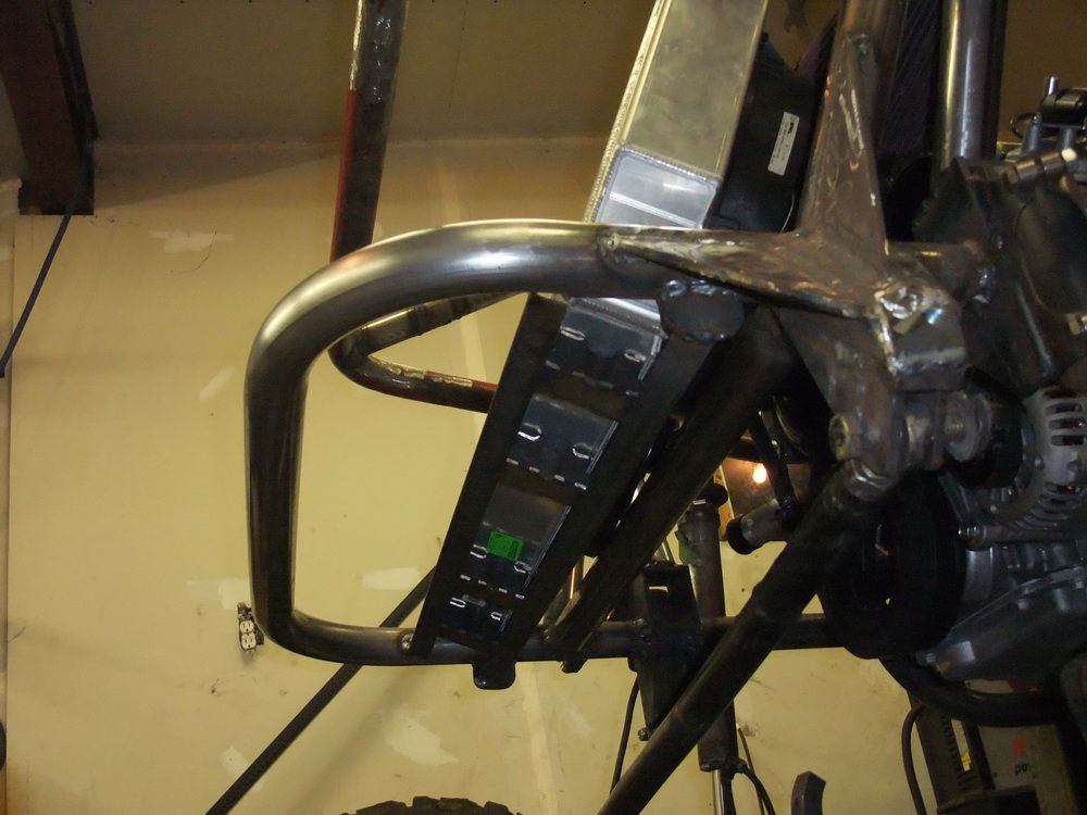 |
Last shot of the lower radiator saddle mount. | ||||||||||||||||||||||||||||||||||||||||
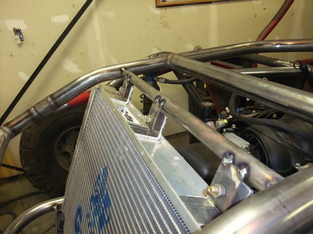 |
For the top mount, I ordered the radiator with mounting brackets welded on. These radiator brackets bolt to brackets on the chassis, with a rubber isolator between each one. These isolators are actually rubber shock bushings from pin-mount style shocks. |
||||||||||||||||||||||||||||||||||||||||
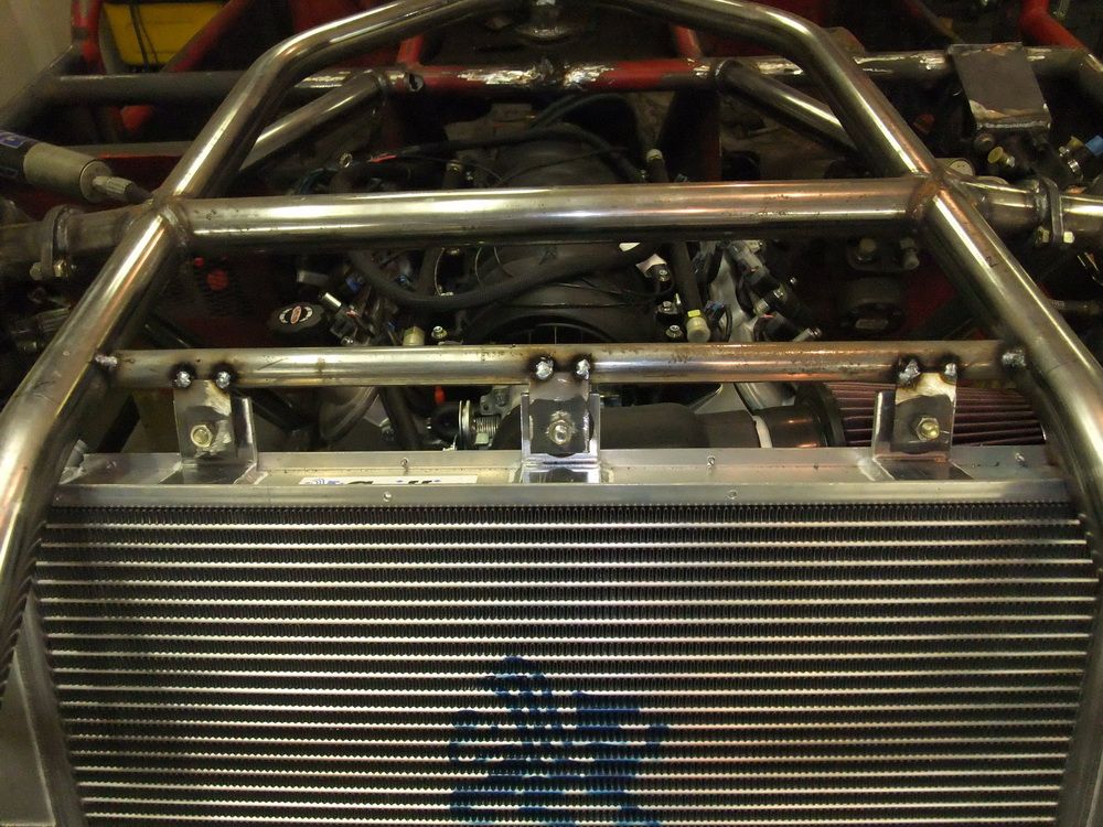 |
Front view of the upper mounting arrangement. | ||||||||||||||||||||||||||||||||||||||||
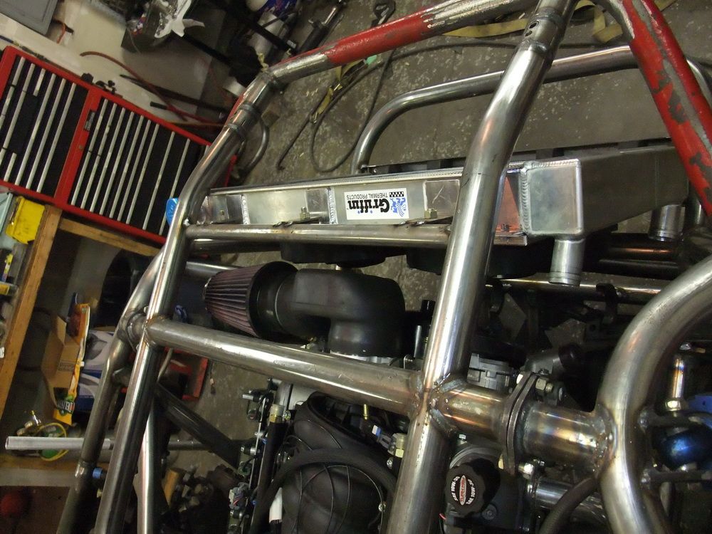 |
Packaging is always a huge challenge when building an off-road buggy... | ||||||||||||||||||||||||||||||||||||||||
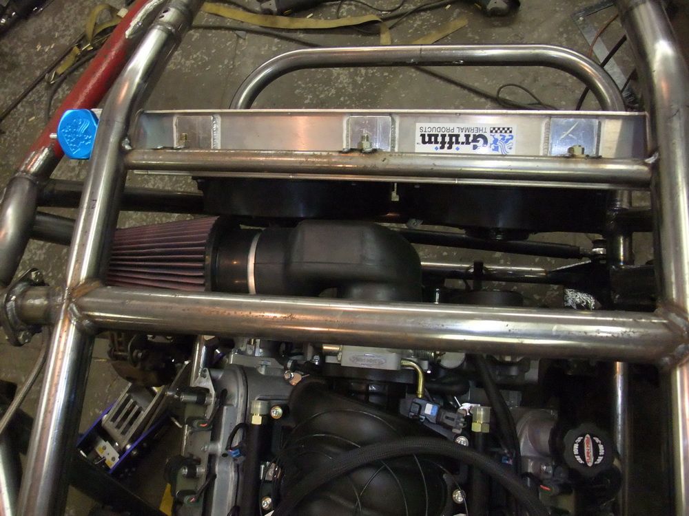 |
... and Griffin's ability to custom-build me exactly what I needed was a huge benefit that allowed me to package things tightly with no wasted space. | ||||||||||||||||||||||||||||||||||||||||
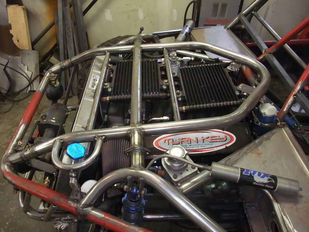 |
To keep the "hood" as low as possible, I built this trick little roll-bar for the radiator cap. | ||||||||||||||||||||||||||||||||||||||||
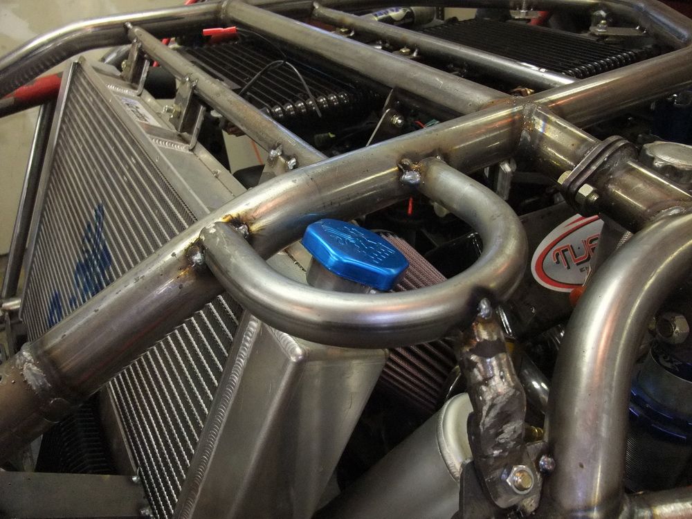 |
Close-up of the rad cap roll-bar. | ||||||||||||||||||||||||||||||||||||||||
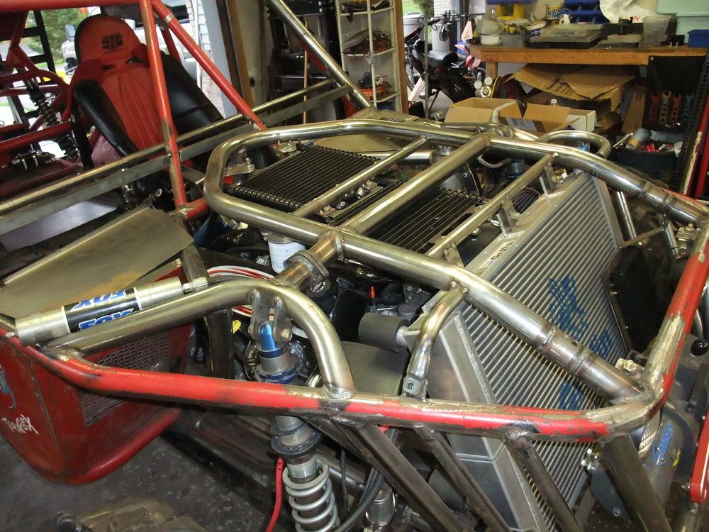 |
I also built a small roll-bar for the right side, just to protect the upper right corner of the radiator. | ||||||||||||||||||||||||||||||||||||||||
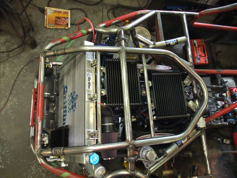 |
I have absolutely no doubt that this awesome rad will keep the 525 HP LS2 cool under any conditions! | ||||||||||||||||||||||||||||||||||||||||
|
|||||||||||||||||||||||||||||||||||||||||
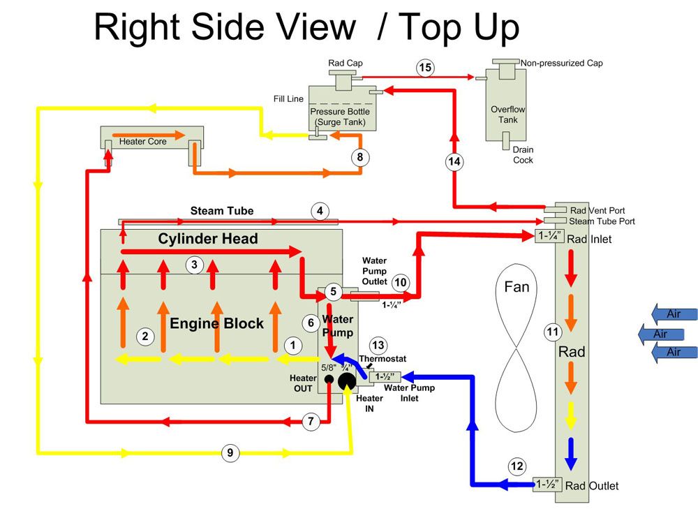
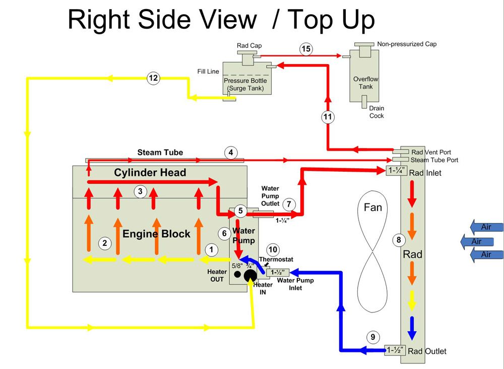
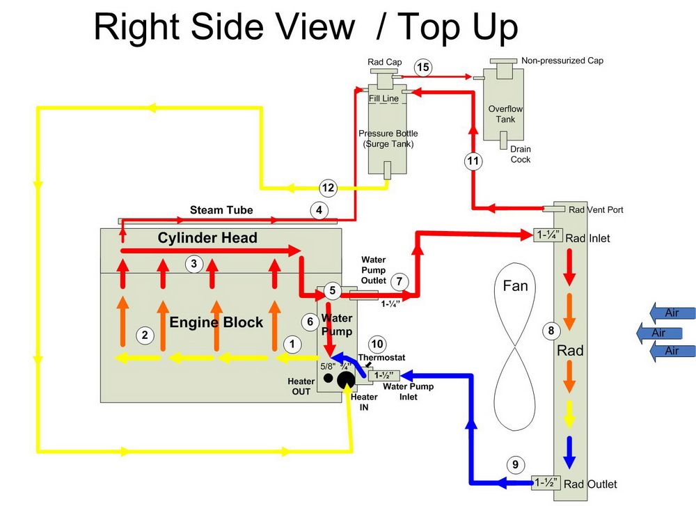
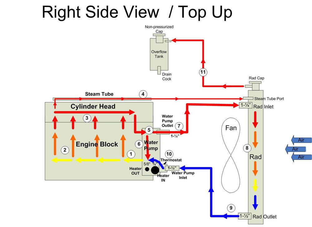
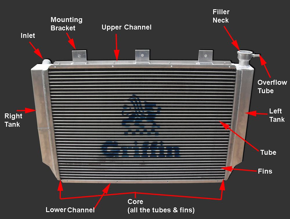

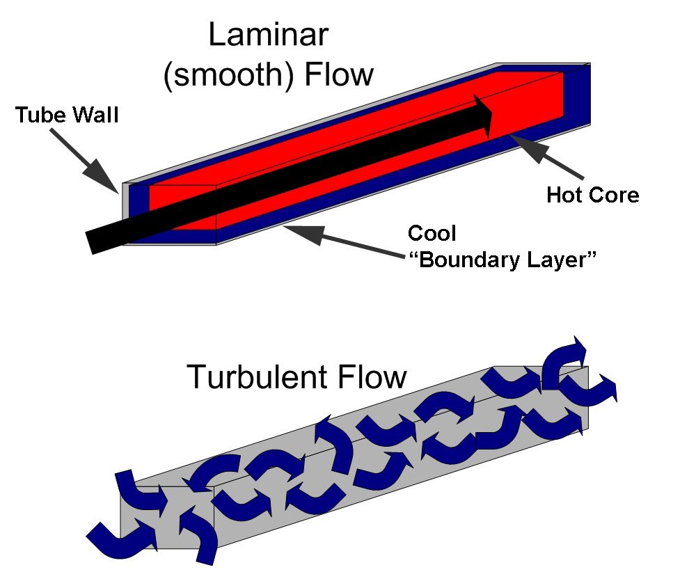
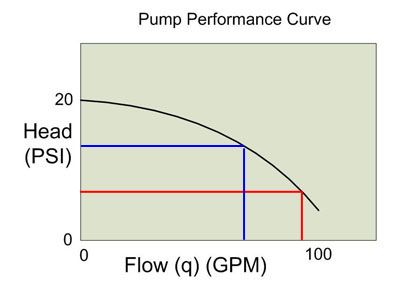
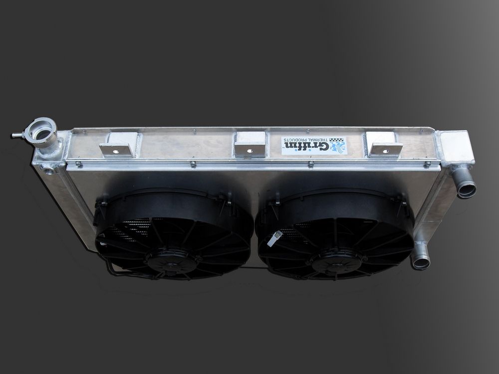
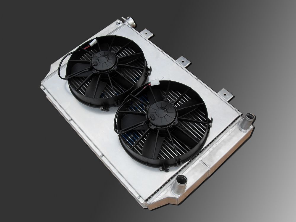
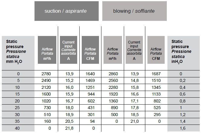
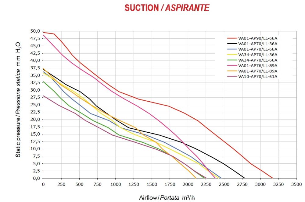
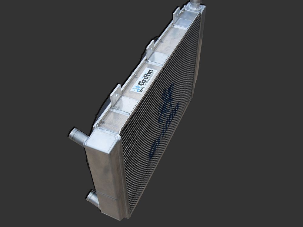

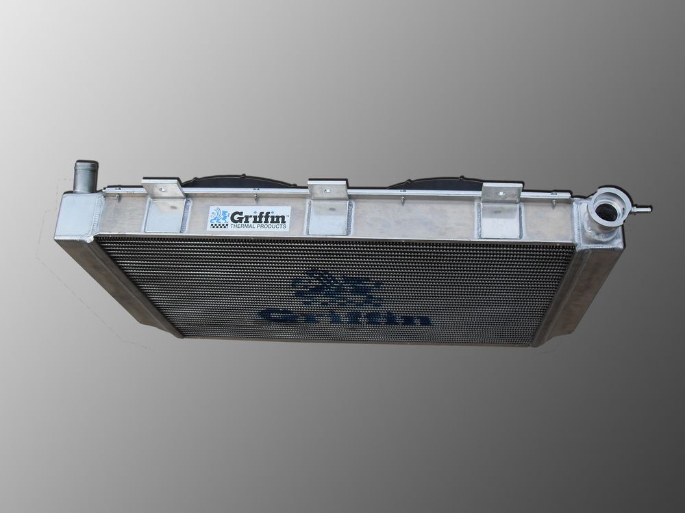

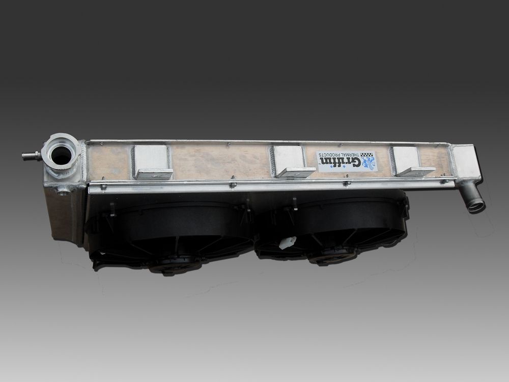
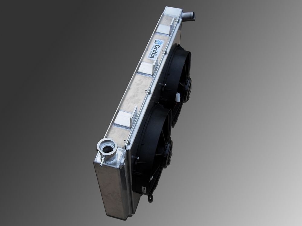
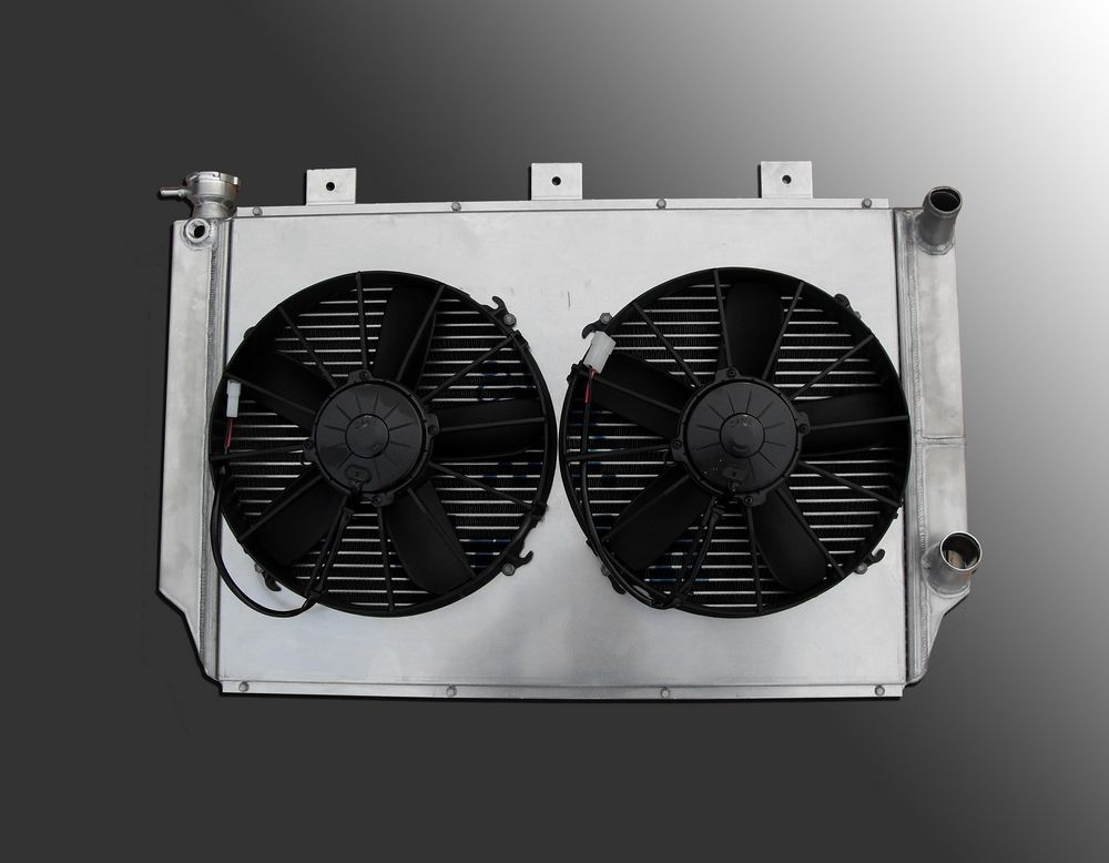
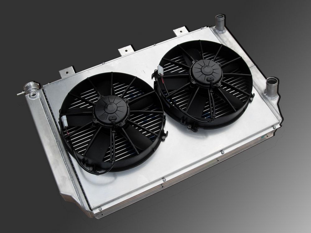
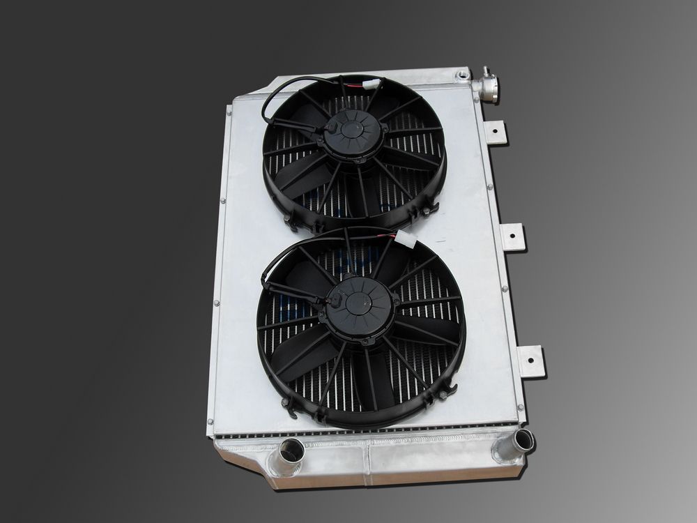
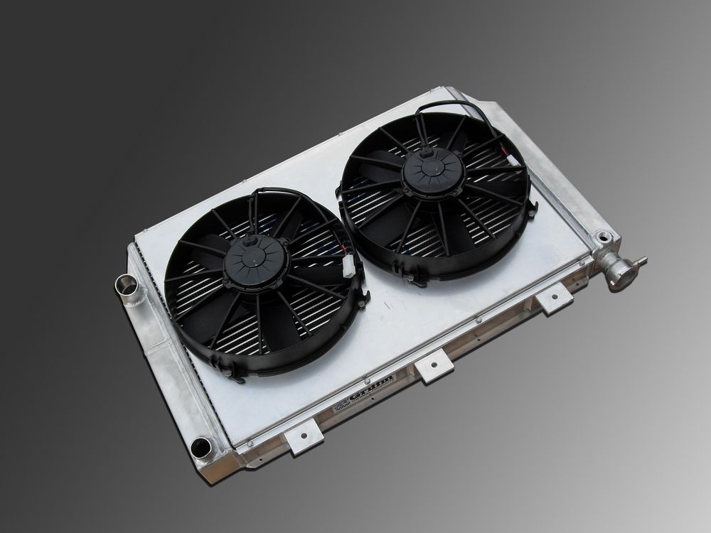
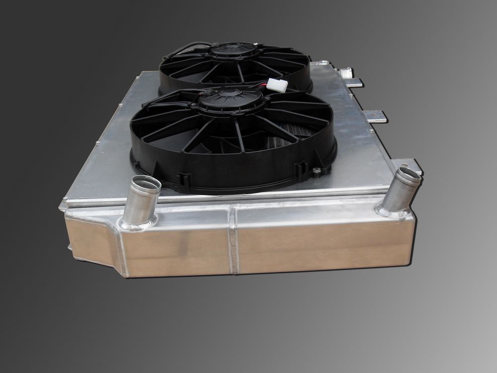
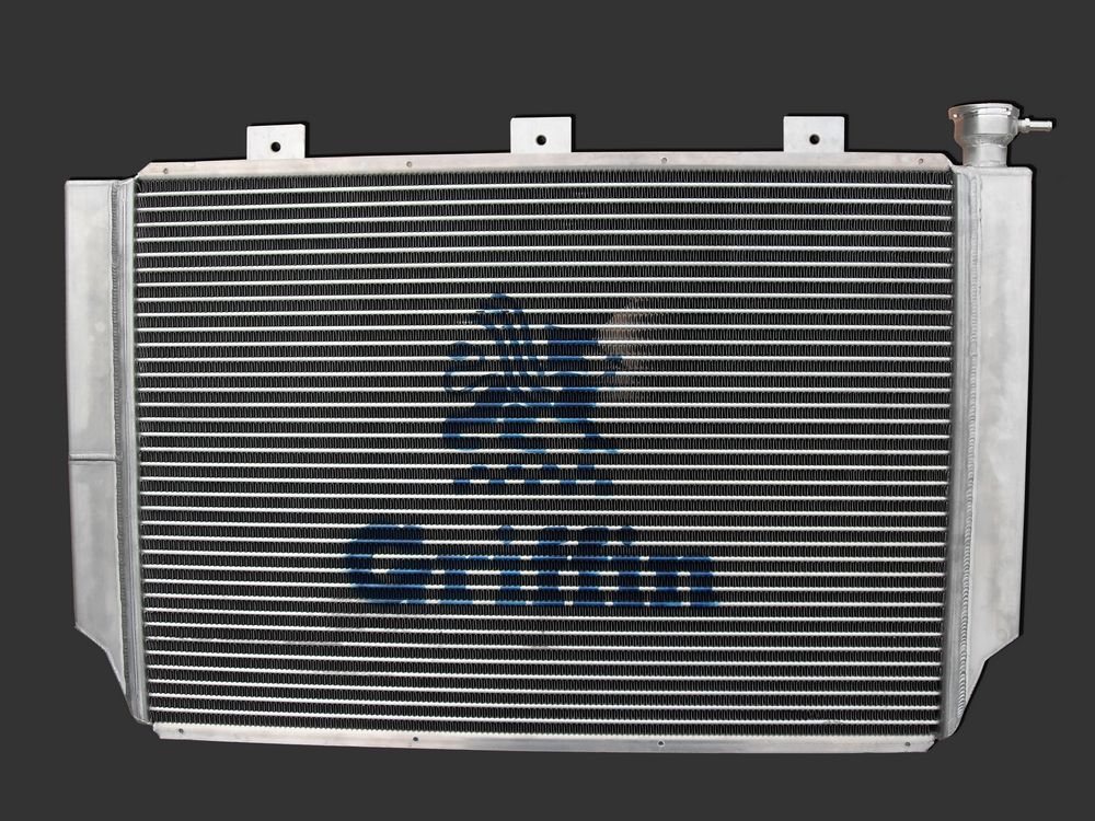

|
Sources: Griffin Thermal Products 100 Hurricane Creek Road 1-800-722-3723 or 864-845-5000 |

|