 |
Cognito Motorsports GM Steering Support Kit By Bill "BillaVista" Ansell |
Introduction'99-'07 Chevy trucks rock! But like every production vehicle on the planet they have their issues. |
 |
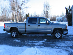 |
In stock trim, like my '07 Classic, one of the biggest of these issues is the stock steering system - it has a weakness that is best addressed sooner than later. |
|
 |
After much research I decided to fix the problem before it became serious and more expensive to fix. With just 3000 km on the clock I installed the GM 8-Lug Pitman and Idler Arm Support Kit from Cognito Motorsports. Here's the why and the how: |
|
Chevy Steering NomenclatureFor those not familiar with some of the terms, let's begin with the names of the parts of the steering system. |
||
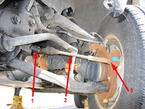 |
1 - Relay Rod (aka Drag Link aka Center Link) 2 - Tie Rod 3 - Tie Rod End |
|
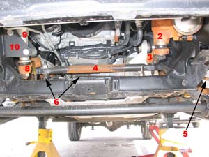 |
2 - Steering Gear Box 3 - Pitman Arm 4 - Relay Rod 5 - Tie Rod 6 - Steering Stabilizer 8 - Idler Arm 9 - Idler Arm Pivot 10 - Idler Arm Pivot Bracket |
|
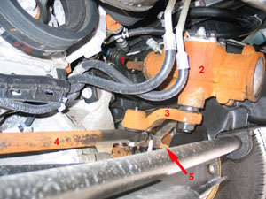 |
1 - Steering Shaft 2 - Steering Gear Box 3 - Pitman Arm 4 - Relay Rod 5 - Tie Rod |
|
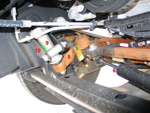 |
6 - Steering Stabilizer 7 - Relay Rod 8 - Idler Arm 9 - Idler Arm Pivot 10 - Idler Arm Pivot Bracket |
|
How the Chevy Steering WorksHere's how the Chevy steering system works: |
||
 |
Driver turns steering wheel which turns steering shaft (1) which turns steering box (2). Steering box provides power assist and turns the Pitman arm (3) in an arc. |
|
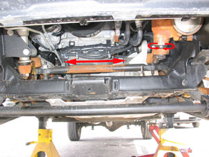 |
Pitman arm is connected to relay rod so that when Pitman arm turns, it pushes the relay rod left and right. | |
 |
On the right-hand side an idler arm pivot (9) and idler arm (8) support the relay rod. | |
 |
The relay rod (1) is connected to the steering knuckle (and therefore the wheel) via a tie-rod (2) and tie-rod end (3). As relay rod moves left and right, the wheels are steered left and right. Simple, eh? Yes - BUT - there is one flaw in the way the system is designed and it concerns the joints between the relay rod and the Pitman and idler arms. The next section explains the problem, it's cause and effects. |
|
The Problem with the Chevy Steering System |
||
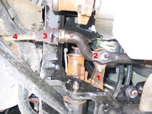 |
As mentioned, the problem stems from the rod-end joints that are part of the idler and Pitman arms (1) and join the arms to the relay rod (2). These joints need to allow for rotational movement between the arm and the relay rod so that the relay rod can be steered left and right. |
|
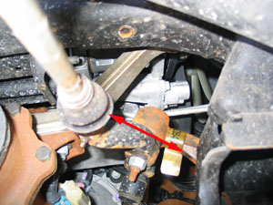 |
The problem is, by allowing for this desired movement, they also allow movement between the arms and the relay rod in a fore and aft plane - i.e. front to back in the truck - as indicated by the double-headed arrow here. | |
This undesired movement causes two things: 1 - First, it causes the rod-end joints in the Pitman and idler arms to wear prematurely. This premature wear is exacerbated by hard use and/or larger tires. There are many stories of the joints being worn out in as little as 40,000 miles, and some in as little as 20,000. Throw in the fact that the joints are an integral part of the entire Pitman (or idler) arm (and not separately replaceable like in old drag-link / tie-rod systems) and you have an expensive, recurring maintenance problem. 2 - Secondly, the fore-aft motion of the relay rod actually has a negative impact on alignment - specifically toe-in. |
||
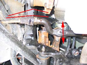 |
This view from below also illustrates, by way of the double-headed arrow, the undesired fore-aft movement between the arms and relay rod. Recall that the wheels are mechanically connected like so: wheel - steering knuckle - tie-rod - relay rod - tie-rod - steering knuckle - wheel. As the relay rod wobbles back and forth, front to back, there will actually be minute changes in the length of this mechanical connection. This is illustrated by the red lines drawn above the tie-rod-to-relay rod joint in the pic at left. Though grossly exaggerated, we can clearly see how a fore-aft motion of the relay rod changes the length of the wheel-to-wheel mechanical connection. This means that it is impossible to set, let alone hold, a consistent toe-in setting for front end alignment. |
|
| The effect may be minor in a brand-new truck, but as the Pitman and idler arms wear (which we just learned they do at an alarming rate) the situation gets worse and worse - with the end result being loss of alignment, loss of steering precision, and uneven, premature tire wear. | ||
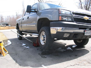 |
You can easily demonstrate this situation to yourself. Jack up one front wheel, leaving the other on the ground. |
|
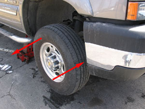 |
Grasp the front and rear sides of the raised wheel and rock it back and forth. | |
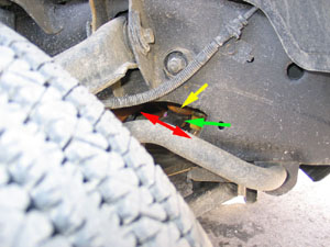 |
While rocking the wheel, look under the truck at the steering linkage. Observe the joint between the idler arm (yellow arrow) and relay rod (green arrow) and you'll see the relay rod moving back and forth, front to back (red arrow). |
|
The SolutionYou've got several options: 1 - Do nothing
2 - Replace the OEM Pitman and idler arms with more rugged aftermarket pieces
3 - Install the Cognito Motorsports brace kit
I chose option 3 - here's a look: |
||
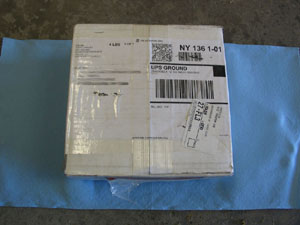 |
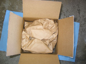
The Cognito kit arrived in one small four-pound box. | |
 |
It was well packaged. | |
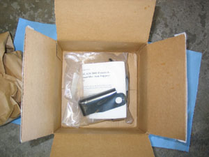 |
And inside everything inside was sealed in plastic bags. | |
 |
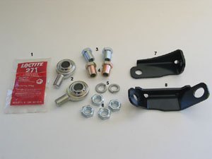
The kit consists of: 1 - A small quantity of Loctite 271 red high-strength thread locker |
|
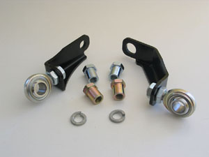 |
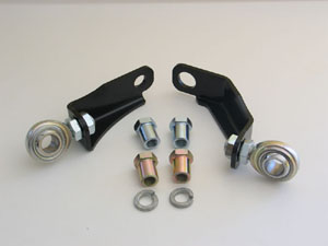
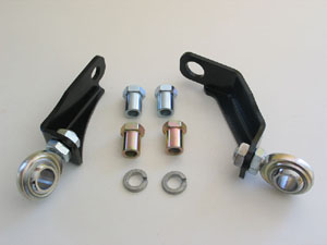
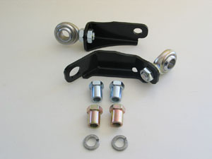
Here's a look at the kit with the rod ends and brackets assembled. | |
Installation |
||
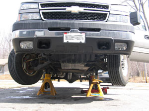 |
It isn't strictly necessary, but the installation is a lot easier if you jack up the front end of the truck and support it securely on jack stands. Never work under a truck supported only by a jack. |
|
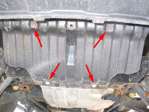 |
If your truck has the factory plastic shroud, its removal is the first step. Undo the four 15mm bolts and remove the shroud. |
|
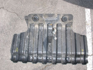 |
Removed shroud. | |
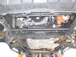 |
This is what the stock steering looks like with the plastic shroud removed. | |
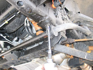 |
Moving the anti-sway bar out of the way isn't part of the instructions and isn't strictly required but I found that it makes the rest of the job much simpler. Remove the four 10mm bolts holding the front anti-sway bar clamps to the frame... |
|
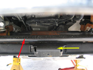 |
...then grasp the anti-sway bar (red arrow) firmly and pull it forward and over the frame extension (yellow arrow). | |
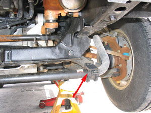 |
Here the anti-sway bar clamp is removed and the anti-sway bar is lowered out of the way. | |
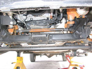 |
This gets the anti-sway bar down and out of the way and only requires the removal of four bolts, so I think it's worth doing as it gives you much more room to work. | |
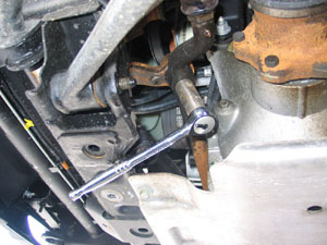 |
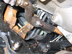
With a 21mm deep socket, remove the lock nut securing the Pitman arm to the relay rod. | |
 |
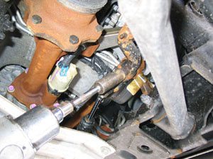
Lock nut removed. | |
 |
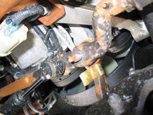
With a 21mm deep socket, remove the lock nut securing the idler arm to the relay rod. | |
 |
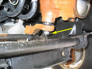
Lock nut removed. | |
 |
With a 1-5/16" wrench, loosen the nut securing the Pitman arm to the steering box shaft. I shot this pic before removing the anti-sway bar - you can see how it's in the way. |
|
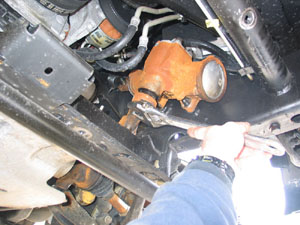 |
If you don't happen to have a 1-5/16" wrench you can get by with a large adjustable wrench. | |
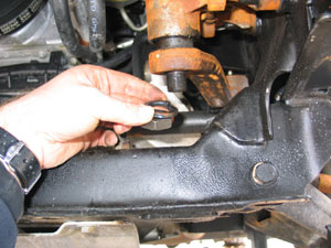 |
Remove the nut and lock washer. | |
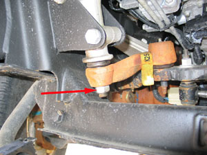 |
Using a 24mm wrench remove the lock nut securing the idler arm to the idler arm pivot. | |
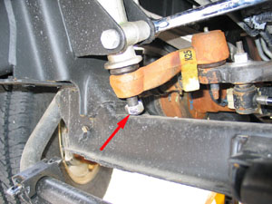 |
Because of the proximity of the idler arm pivot to the frame, you may find that there is insufficient clearance to remove the nut. | |
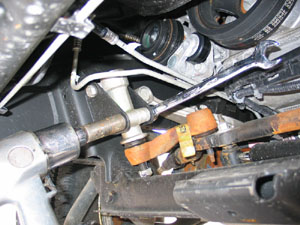 |
In this case, remove the two bolts securing the idler arm pivot to its bracket... | |
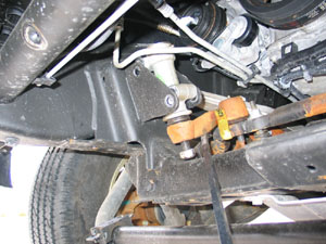 |
...and use a pry bar to lever up the idler arm pivot and give sufficient clearance to remove the nut. | |
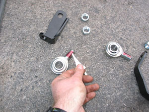 |
Apply a little thread locker to the threads of each of the rod ends. | |
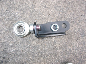 |
Thread a jam nut all the way onto each rod end. | |
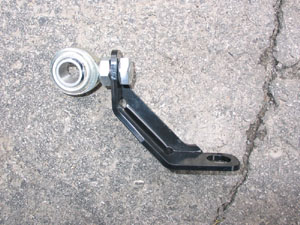 |
Then insert a rod end into the 5/8" hole in each of the brackets. Next, loosely thread on the second jam nut. Do not tighten the jam nuts at this time. | |
 |
Make sure you insert the rod ends into the brackets in the correct orientation, as illustrated in this pic. | |
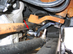 |
Place the Pitman arm bracket in place as shown here. Place a 9/16" lock washer in place on the Pitman arm stud as shown (red arrow); then simultaneously slide the large hole in the bracket over the steering box shaft and slide the bore of the rod end over the Pitman arm stud. Holding the bracket in place, reinstall the lock washer and nut on the steering box shaft and finger tighten. |
|
 |
The Cognito kit comes with silver- and gold-coloured shank nuts. The shank nuts are inserted through the bores of the rod ends and tightened onto the studs of the Pitman and idler arms. The gold-coloured shank nuts have a coarse thread and are for use with factory or OEM Pitman and idler arms. The silver-coloured shank nuts have a fine thread and are for use with aftermarket Pitman and idler arms. Depending on the brand or combination of brands of arms you have on your truck, you may need to use either the gold nuts, the silver nuts, or one of each - just match the thread of the nut to the thread of the stud. Vernon from Texas, reports: "I ended up having to use one silver and one gold to install the braces on my new Napa Chassis (made by Spicer) idler and pitman arms. " |
|
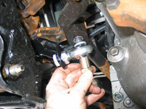 |
Apply some thread locker to the threads of the correct shank nut, insert it through the bore of the rod end... | |
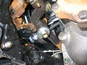 |
...and finger-tighten it onto the Pitman arm stud. | |
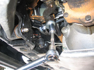 |
Tighten the shank nut with a 7/8" socket to 85 ft/lbs. | |
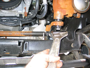 |
Tighten the steering box shaft nut to 180 ft/lbs. | |
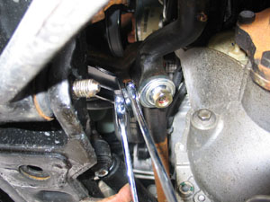 |
Using a pair of 15/16" wrenches, tighten the jam nuts to 85 ft/lbs, jamming the Cognito bracket between them. | |
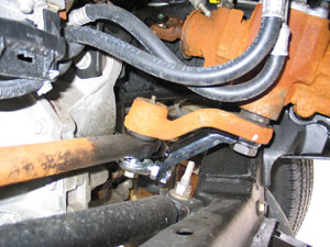 |
The installed Pitman arm bracket. | |
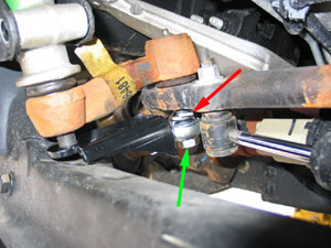 |
As on the Pitman arm side, slip the idler arm bracket in place over the idler arm pivot and idler arm stud, making sure the 9/16" lock washer is in place between the rod end and relay rod (red arrow). Apply some thread locker to the threads of a shank nut and thread it onto the idler arm stud to hold the bracket in place (green arrow). |
|
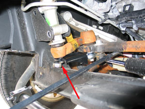 |
Using a pry bar, lever up on the relay rod to provide enough clearance to reinstall the nut on the idler arm pivot. | |
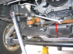 |
Reinstall the bolts securing the idler arm pivot to its bracket and tighten to 73 ft/lbs. Use a wrench or other support between the relay rod and frame (red arrow) to prevent the wrench on the nut from scratching the polished shaft of the steering stabilizer as you tighten the bolts. |
|
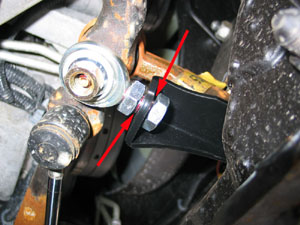 |
Check to make sure that the jam nuts aren't tight against the bracket yet, so that nothing binds as you tighten the other fasteners. | |
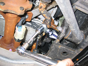 |
Tighten the shank nut with a 7/8" socket to 85 ft/lbs. | |
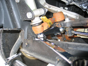 |
Tighten the idler arm pivot nut to 85 ft/lbs. Then, using a pair of 15/16" wrenches, tighten the jam nuts to 85 ft/lbs, jamming the Cognito bracket between them. |
|
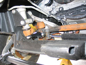 |
The installed idler arm bracket. | |
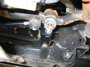 |
Installed idler arm bracket, seen from below. | |
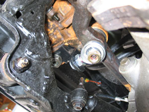 |
Installed Pitman arm bracket, seen from below. | |
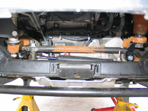 |
The complete Cognito kit installed. | |
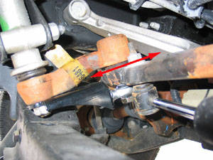 |
Here's how the kit works: The Cognito bracket "captures" the relay rod in a "double-shear" mounting, meaning that the relay rod is supported on both sides. Also, the bearing in the rod end attached to the Cognito bracket rotates in its race, allowing the steering to move left and right, but cannot move fore and aft in its race. Combined, these features mean that the relay rod no longer moves in the unwanted fore-aft plane as indicated by the red arrow. |
|
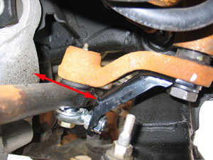 |
This pic shows the installed Pitman arm bracket. It is easy to see how it prevents the relay rod from moving in the undesired plane indicated by the red arrow. | |
 |
To complete the job, pry the anti-sway bar back over the frame extension and into place, then re-attach the clamps to the frame with the four 10mm bolts, tighten to 37 ft/lbs. | |
 |
Re-attach the plastic shroud... | |
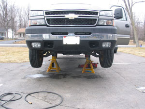 |
...and you're done. | |
|
||
 |
Sources: Cognito Motorsportshttp://www.cognitomotorsports.com/ Toll Free: 866.426.4648 Phone: 661.588.8085 Fax: 661.588.8295 Address: 1800 Art Street, Bakersfield, CA 93312 |
|
