 |
Ask BillaVista By Bill "BillaVista" Ansell |
IntroductionBillaVista answers reader's questions in this one-off article. |
 |
Q: I have a question (about my Warn 8274 winch). I've got power out only. It won't power in. What’s the best way to test the solenoids? Is it usually 1 or 2 ‘noids that go when this occurs? – AnthonyA: Anthony, Winch checkStanding in front of your 8274, and looking at the motor case you will notice that there are 3 studs or terminals on the top of the winch-motor housing. From left to right, they are the:
You can test your winch with no solenoids or even emergency operate your winch in the field using jumper cables as follows: To test power-in operation: attach one (+) end of a jumper cable to 12v battery (+), the other (+) end to the F1 motor terminal (bottom left). Attach one (-) end of the jumper cable to battery (-), the other end to the winch motor case. Using a separate heavy-duty jumper cable (such as another battery booster cable) jumper the armature motor terminal, A, to the F2 terminal. With all connections to the motor’s terminals it is advisable to leave the nuts in place on the studs to avoid damaging the threads. If all is well the winch will turn in the power-in direction. To test power-out operation: proceed as above except attach the 12v battery (+) cable to the F2 motor terminal and jumper the armature motor terminal to the F1 terminal. In an emergency you could use a long screwdriver with an insulated handle to jumper from the A terminal to the other motor terminals, (holding only the handle and making sure the stem or blade touches nothing else) but this is quite dangerous and is not to be recommended. In either case, if the motor doesn’t turn, either the motor is unserviceable and will need repair/replacement, or there is a problem in the gear-train which will require a full tear-down and rebuild. Note that this procedure is also great for pre-purchase checking of an old winch if it has bad or missing solenoids. Testing Solenoids |
|
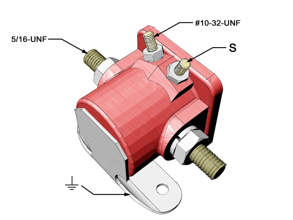 |
Figure 1 - SPNO Solenoid |
The typical winch solenoid, and certainly those used with the 8274 are of the “Single Pole Normally Open” (SPNO) variety (Figure 1). This simply means that they are really just electro-magnetic switches, relays if you will. They have 2 large 5/16-UNF studs for conducting the high current and a small “S” terminal (normally #10-32-UNF) used for switching them (most actually have 2 small terminals, but only the one labelled “S” on the top right is of interest to us). In operation they are quite simple: When you apply a 12v(+) signal to the small S terminal, the plunger inside closes, connecting the 2 large studs together. Remove the 12v(+) signal from the S terminal and the plunger opens, interrupting the flow of current between the 2 large studs. Note that solenoids ground through their cases, and in the case of the 8274 to the metal solenoid bracket, and through it, to the motor housing itself. You can test your solenoids as follows:
Finally, as for replacing solenoids in pairs or not, my advice is this: remember that a solenoid is an electro-mechanical device, with moving parts, and subject to some pretty harsh operating conditions, especially on the front of a 4x4. If you find that your winch will either not power in or not power out and you have isolated the problem to the solenoid pack, I would always recommend replacing the solenoids on the affected circuit (in or out) in pairs as it is quite likely that even if only one has gone, the other may not be far behind. This way, you can replace both solenoids, and if upon individual testing you find one of the pair of solenoids on the malfunctioning circuit is operational, you can keep it as a trail spare. Q: I am looking for a 14 bolt for a swap in my YJ, and came across a guy that is parting out a 2002 Chevy 1 ton. He said the rear axle is a 14 bolt, with disc brakes, etc. I have not seen the axle yet, but wanted to check if you would know if Chevys came with 14 bolt axles after 2001? – GuiA: Gui, The factory disk brakes many will carry in stock form may be a bonus, but before you decide I would check carefully into the price of adapting the brakes to your rig (they probably have metric fittings) and also the cost of brake parts for down the road – some of the fancy new mini-drum-in-the-rotor parking brake set-ups work great but parts are unbelievably expensive. Don’t forget to check prices for bearings and axle shafts too. Remember that one of the great strengths of the traditional “14 bolt” is not only its dime-a-dozen availability but also the dirt cheap price for parts and build-up, including lockers and easy disk-brake swapping. Not to mention, there probably aren’t many 2000+ spare shafts out there yet, and those that are will likely command top dollar for stock-replacement. In the end, unless the deal is unbelievable, you’re probably better off with an earlier axle. Q: I have a question about the hub types for the 14FF (14 bolt full-floating rear axle). I'm basically wondering why was the SRW/Van given the type A hub and the DRW/CC vehicles given the type B hub? Is there a strength difference or was it just two teams of engineers working on those projects and came up with two different looking hubs with the same strength capabilities? I'm going to swap in a 14FF in my Blazer, but I want to have as much info as possible before I jump in on this project. - JohnA: John, Q: I am in the process of putting together my hydro steering. I have everything set up, but am having one hell of a time getting the system bled. The flow of my setup is: reservoir -> pump -> orbital -> cylinder -> trans cooler -> reservoir.I've been bleeding this thing for 2 freekin’ days now and can't get the pump to stop howling. I bypassed the cooler and it bleeds out fine and the pump is quiet. I've been told by two sources that I trust that I don't need the cooler and should just bypass it. I would feel much more comfortable with the cooler left in the system so... Did you have any trouble bleeding your system? I have rerouted the cooler lines a few times now. The flow to the cooler is from the orbital to the bottom fitting on the cooler. The top cooler fitting then goes to the res. The bottom of the cooler is about 1 inch higher than the orbital. The top of the cooler is about 8 inches lower than the res. Any ideas? - Scott N. A: Scott, You've obviously isolated the cooler as the cause - what size are the passages? Is it new? Could there be any restrictions? If it’s new, could it be a defective unit or could there be packing material lodged in the lines causing a blockage? On the other hand, if it is used, could it be restricted or blocked up with accumulated crud? If there is a blockage or the lines of the cooler are too small, it will increase the velocity of the fluid due to the venturi effect, which could cause turbulence and/or a pressure drop (fluid dynamics says the faster the fluid the lower the pressure - same concept by which an airplane wing generates lift) If the restriction is great enough, the fluid speed can increase to the point where the pressure at the restriction falls low enough that the fluid begins to cavitate. Even if cavitation isn’t occurring, restrictions or inadequate plumbing size for a given flow rate can cause turbulent flow in your circuit, which in itself can whip air into the fluid (like beating an egg till it’s frothy). In either case, aeration of the fluid is generally bad news for a hydraulic circuit and can certainly cause a lot of pump noise. Cavitation happens when the pressure in the fluid falls below the vapour pressure of that fluid at that temperature. In other words, when the physical conditions are right - a "change of state" spontaneously occurs, and the liquid turns to vapour, creating a vapour pocket or bubble that will then collapse very rapidly as it is exposed to higher surrounding pressure. The individual bubbles that form and then collapse are very small, even microscopic, but they form and collapse very quickly, with great force, and in great numbers. It's roughly analogous to condensation forming on your cold drink glass on a warm summer day. You have H2O, which can be solid (ice), liquid (water) or gas (water vapour). Warm air can hold more water in suspension in vapour form than cold air. So if you take warm air full of water vapour and cool it, (that's what happens when that warm, vapour-laden air comes into contact with your cold drink glass) the water vapour will spontaneously change state from gas to liquid, and condensation forms (and runs down the glass and makes a ring on the table if you didn't use a coaster!) So, in a hydraulic circuit, if a pressure drop occurs (perhaps because of venturi effect or turbulence) and the pressure drops to a point below the vapour pressure of the fluid (whatever it may be) - voila - state change, vapour "bubble" and then when that vapour bubble encounters a region of higher pressure - it collapses with a "pop" and that's the noise you hear. Can you observe the reservoir and see if the returning fluid is more frothy when the cooler is in the circuit? This could help you determine if the cooler is indeed causing air to be introduced into your fluid for one reason or another. You could always run your system without the cooler and see if you can get away without it. As long as the temp doesn't get too high (you should aim for an operating temperature of 86-140°F (30-60°C) - the rule-of-thumb is that the useful life of an oil is halved for every 4.4°F (8°C) the temperature rises above 140°F (60°C). That said, you're better off a little warmer than with air in the fluid. Of course, the better the fluid you use, the more resistant to thermal breakdown it will be, and therefore the higher system temperatures you can tolerate. Other things to check, that can allow air into the system include:
The last thing to note is that often a pump can be noisy as the system warms up, and then it quietens down. This is because there is considerable air suspended in cold hydraulic fluid. As the fluid warms, air is released into the system and you get a noisy pump. Eventually as the fluid warms up to operating temperature all the air will be released and, in a properly designed and vented system, this air is removed before leaving the reservoir and entering the inlet area of the pump. In some cases, special return line configurations or air bleed-valves are needed to remove air from the system. Q: My dad and I scored a great deal on an old industrial 3-phase welder. It came with a cart that was worth the price alone, but we were wondering if it is possible to convert it to operate off 220v 2-phase power. – AdamA: Adam, The AC in AC Power stands for “alternating current”, the frequency of which in North America is 60Hz (or 60 cycles per second). Common household/shop power is also either 120 volts or 240 volts. The difference between 120v and 240v has no effect on our discussion of 1 and 3-phase power, and so for the sake of simplicity I shall use 120 volt 60Hz AC power in the rest of my explanation – but the differences between 1 and 3-phase power are equally true whether we’re talking about 120v or 240v. 60Hz AC power means that the electrical current supplied to your house or shop regularly and gradually alternates from 0 volts to positive 120v back through 0v, down to negative 120v and then back to 0v again. It does this in a regular smooth cycle called a Sine wave, seen in Figure 2. In the case of 60Hz power, the current goes through this cycle 60 times every second – Hertz (Hz) is the unit for 1 cycle per second. Note that the voltage will be at maximum value twice during each cycle – once at (+)120v and once at (-)120v – in other words there will be max voltage 120 times per second for 60Hz AC power. |
|
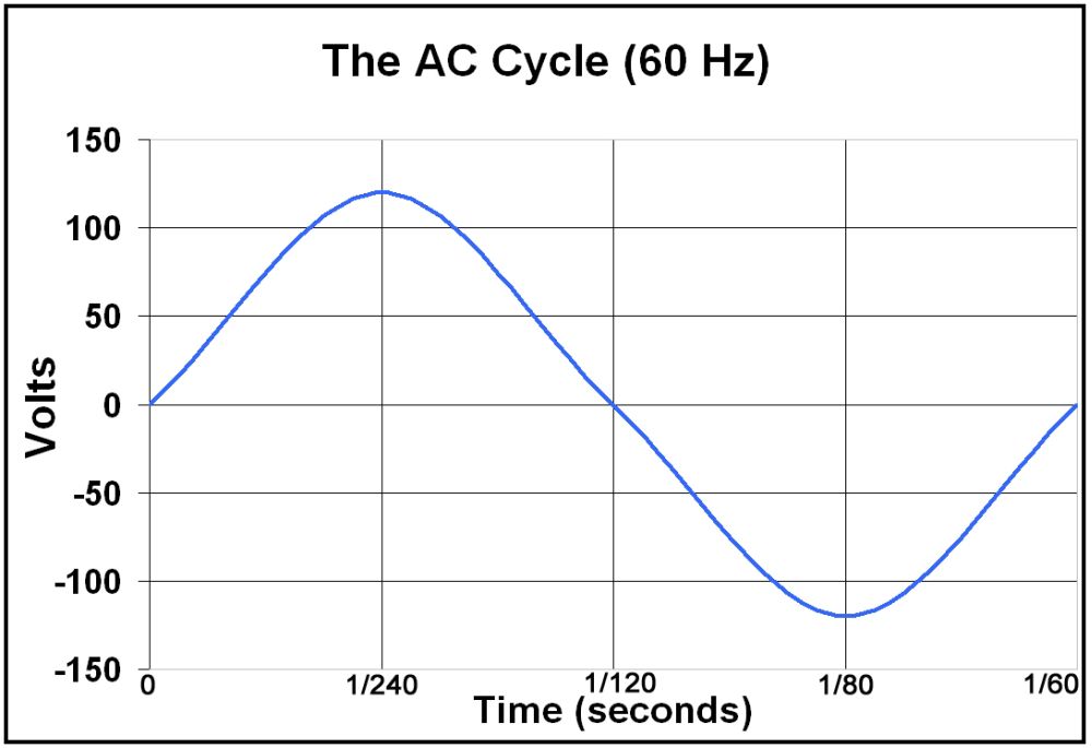 |
Figure 2 – a single 60Hz AC cycle |
Why is this important? When we apply single-phase 60Hz AC power to an electrical motor, the current magnetizes the steel poles of the motor every time it builds from zero to max voltage, whether that voltage is negative or positive, so again, 120 times per second. It is this magnetization that powers the motor – each time the poles are magnetized it “pushes” the motor around, much like each time a cylinder fires it “pushes” the crankshaft around. In this example, our electrical motor is given a “push” 120 times per second – just like a single-cylinder engine running at 120 rpm. This single-phase power is fine for smaller electrical motors. Take, for example, a bench grinder powered by an electrical motor that has a rotor or armature that is just 2 inches in diameter. The circumference of that rotor would be π(d) or 6.3 inches. If we run this motor at 1800 rpm, it rotates 30 times per second. Since it gets 120 “pushes” per second, and rotates 30 times a second, this translates into 120/30 or 4 pushes per revolution. Recall that every rotation is just 6.3 inches and we can see that the motor only has to turn through 6.3/4 or about 1.5 inches between pushes – no problem. But what if the electrical motor was a large industrial piece with a rotor of, say, 24 inches in diameter? When we do the math we find that this motor, at 1800 rpm, powered by single-phase 60Hz AC power, would have to turn through almost 19 inches between “pushes” – it would never be able to maintain power, and certainly wouldn’t be smooth in operation. What are we to do? This is where 3-phase power comes in. As we know, industry will often use 3-phase power to power large, industrial equipment. If the single-phase electric motor is like a single-cylinder engine, a 3-phase electric motor is like a 3-cylinder engine – i.e. able to produce more power. It works like this: Instead of having a single winding inside the electrical motor that carries the current (as in a single-phase motor) a 3-phase motor uses 3 separate windings not connected to each other at all. These windings are offset from one another, mechanically and electrically, by 120°. In this fashion, each winding reaches maximum voltage 120 times per second as before, but they all do so in turn, in a regular, smooth pattern. The net result is the motor receives 3 times the number of “pushes” as before. Of course, and this is the key, we must supply a 3-phase motor with 3-phase electrical power – power that must be specially generated so that the peak and zero voltages of each winding occur in the right order and at exactly the right time (just as in a multi-cylinder engine each cylinder must fire in the right order at exactly the right time). There is simply no practical or economical way to convert standard single phase power into 3-phase power – it would be like taking a single-cylinder engine and trying to add on a couple of extra cylinders yourself – not impossible but ludicrously impractical. In summary – you can think of electrical motors like engines, and “phases” like cylinders. More phases equal more power, but there’s no practical way to convert between them. In other words, you bought a nice cart and a conversation piece / unique coffee table base! Q: I was reading your "Steering Box Tapping" article and want to ask you a question about the tap. You state: "Commonly the holes are drilled and tapped to 1/4" NPT. That would mean drilling a 7/16" hole, then using a 1/4' NPT tap (18 Threads per inch)."I can only find 1/4" x 20 threads (course) and 1/4" x 28 threads (fine). Where can I find this 1/4" x 18 thread tap that you talk about, or is there a mistake in the article. –Dean A: Dean, What you are finding are taps for cutting Unified National (UN) threads - those are the threads that are used for threaded fasteners (nuts and bolts). What you need is a tap to cut a National Pipe Taper (NPT) thread. NPT threads are tapered threads common in plumbing and hydraulics. As the name suggests, the threads are actually slightly tapered, so that a leak-free fit can be obtained as the parts are screwed together. A 1/4" NPT fitting will have an actual threaded OD of nearly half an inch, and indeed requires a 7/16” hole be drilled or reamed for tapping the hole. The proper tap may be a challenge to find, but should be available from a good machine shop tool supplier or hydraulics outlet or other quality tool supplier. They are also available from good on-line suppliers like McMaster-Carr (http://www.mcmaster.com). Be warned - they're not cheap - you'll likely have to pay at least $30 US for one. It will have an OD of 0.459", have 18 threads per inch, and the taper on it will be between 23/32 and 27/32 inches per foot. |
|
|