 |
The Alternator Bible By Bill "BillaVista" Ansell |
*Note: This article assumes that the reader has read and understood "The 12V DC Series Part 1 - 12V DC Basics". In this article, unless specified otherwise, all discussion of electrical current flow is done in "conventional notation."
OperationThe next time some long-haired, sandle-wearing, tree-hugging, peace-loving, soap-dodging, Prius driver looks over at your truck with it's massive array of off-road lights, pumping stereo, and 15,000 lb winch and gives you that supercilious, holier-than-thou sneer that they seem to be so expert at (it must be explained in the Prius owner's manual / book of hypocrisy) - feel free to explain to them that your rig is entirely solar powered. I recommend using small words and speaking slowly as if conversing with a small and rather dim-witted child. But you will be telling them the truth. You see, the fact is, EVERYTHING on this earth is solar powered. ALL our energy has always come, and will always come, from the sun. Everything we power ultimately derives its energy from the sun - even your Big Block. You see, many millions of years ago the sun's rays shone down on the earth - making plants grow. Animals (dinosaurs) ate those plants. The plants and animals died, fell down, and over a long, long time got squished into oil. A few million years later some guy from Texas drills into the ground, extracts the oil, refines it into gasoline and you put the gasoline in your truck and it goes Vroom Vroom. Presto! - solar powered Big Block! All kidding aside, there is an important concept here in this entirely true, if somewhat fanciful, description of energy. And of course, that concept is our old friend the law of the conservation of energy: "Energy can neither be created nor destroyed, merely converted from one form to another." How does this relate to alternator tech? Simple - the alternator is the last conversion device in a long line that convert solar energy into the electrical energy that powers your lights, radio, winch, etc. Solar energy becomes chemical energy stored in gasoline as described above. The vehicle's engine converts the gasoline's chemical energy into mechanical energy (the energy of moving things). The alternator, driven by the engine via a belt, turns this mechanical energy into electrical energy to charge your battery, power your lights, etc. Let's look at exactly how it does that. Basic DescriptionAn alternator is an electromechanical device that converts mechanical energy to AC (alternating current) electrical energy, converts the AC to DC by rectifying it, regulates the DC voltage output to 12 Volts, and supplies this 12V DC power to charge the vehicle's battery and power the electrical components. An engine-driven belt spins a magnet (called the rotor) inside a coil of wires (called the stator) which, by the laws of electromagnetism, induces an AC electrical current in the wires. The AC current is then rectified (turned into DC current) by a series of "electrical one-way valves" called diodes, and is output as DC current to the vehicle's electrical system. OK, that was quite a mouthful. Let's break it down step by step. The Laws of ElectromagnetismI don't want to teach a physics class here - not least because I'm wholly unqualified to do so - but a very basic understanding of two fundamental laws of electromagnetism will vastly ease our understanding of how an alternator works. The two complimentary laws are:
Electrical currentWe should have a good understanding of what an electrical current is from "The 12V DC Series Part 1 - 12V DC Basics". Magnets & Magnetic Fields |
||||||||||||||||||||||||||||||||||||||||||||||||||||||||||||||||||||||||||||||
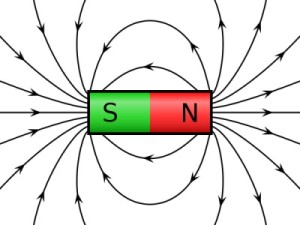 |
Strictly speaking, a magnet is any material or object that produces a magnetic field. A magnetic field is an invisible force that can act on (attract or repel) other magnetic objects. Magnets have "poles" - a north pole and a south pole. By convention, we say that the magnetic field lines leave the North pole of a magnet and enter the South pole of a magnet. At right is an illustration of a simple bar magnet, like the type we played with as kids. As per convention, the magnetic field, or lines of magnetic force, are illustrated as originating from the North (red) pole, and terminating at the South (green) pole. |
|||||||||||||||||||||||||||||||||||||||||||||||||||||||||||||||||||||||||||||
Types of Magnets.There are three basic types of magnets - permanent, air-core, and electromagnet. Permanent Magnets |
||||||||||||||||||||||||||||||||||||||||||||||||||||||||||||||||||||||||||||||
 |
A permanent magnet gets its magnetism because of the material from which it is made. Principally, magnetic materials are those in which the electrons mostly spin in the same direction. We needn't get into any more detail than that. Magnetic materials include iron, nickel, & cobalt, as well as less common elements such as neodymium (Nd) and samarium (Sm). (You may have read spec sheets or advertisements for stereo speakers featuring "neodymium magnets.") Pictured at left is a simple bar magnet made of iron. Interestingly, if you take a bar magnet and break it into two pieces, each piece will again have a North pole and a South pole. |
|||||||||||||||||||||||||||||||||||||||||||||||||||||||||||||||||||||||||||||
Permanent magnets never lose their magnetism - hence the name. You may have seen spec sheets or advertisements for electric motors, particularly in winches, that feature "permanent magnets". Air Core Magnet OK, this is where it starts to get more interesting (and relevant!). It turns out, that if we wrap a piece of wire into a coil shape and pass an electrical current through it, it produces a magnetic field, just as if it were a bar magnet. Precisely why it should do this is WAY beyond the scope of this article (and my ability to explain) so I shall ask you to simply believe it is true. Of course, you could always try it and prove it to yourself! Anyway, such a device is called an "air core" magnet because the "core" between the coils of wire is, well, air! Physicists are a clever lot, but not always terribly creative with their naming of things - which is probably a good thing! |
||||||||||||||||||||||||||||||||||||||||||||||||||||||||||||||||||||||||||||||
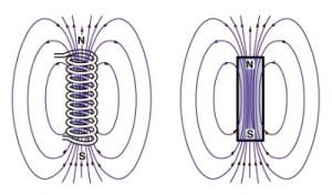 |
This picture illustrates an air core magnet on the left and a bar magnet on the right. The similarities in the magnetic fields are apparent. |
|||||||||||||||||||||||||||||||||||||||||||||||||||||||||||||||||||||||||||||
Electromagnets The trouble with air core magnets is that the magnetic field produced is very weak, and therefore not of much practical use. In contrast, and electromagnet can be capable of generating extremely strong magnetic fields. |
||||||||||||||||||||||||||||||||||||||||||||||||||||||||||||||||||||||||||||||
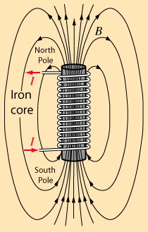 |
An electromagnet, also called an "iron core" magnet, is similar to an air core magnet, except that instead of there being a core of air between the coils of wire, there is a core of magnetic material such as iron (again, hence the descriptive but uninspired name: "iron core magnet"!). The iron core of an electromagnet can produce magnetic fields many hundred times stronger than an air core magnet. An advantage of electromagnets is that, because they depend on the flow of electrical current through the coil of wire (sometimes called the "windings"), they can be turned on and off. |
|||||||||||||||||||||||||||||||||||||||||||||||||||||||||||||||||||||||||||||
  |
These properties of strength of magnetic field generated and the ability to be turned on or off make the electromagnet a hugely practical tool, as illustrated here. | |||||||||||||||||||||||||||||||||||||||||||||||||||||||||||||||||||||||||||||
Your Own Electromagnet |
||||||||||||||||||||||||||||||||||||||||||||||||||||||||||||||||||||||||||||||
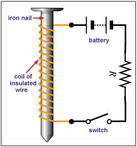 |
Many of us will have created our own electromagnet at one time or another in a simple science experiment like the one pictured at left. The switch can be as simple as holding the wire onto one of the battery terminals or not. You can make your own and experiment by using it to pick up other small magnetic objects like paper clips or small nails. NOTE: You must use a small resistor (as pictured), or some other resistance like a lightbulb, in the circuit, otherwise you will create a short circuit. |
|||||||||||||||||||||||||||||||||||||||||||||||||||||||||||||||||||||||||||||
But what has all this to do with alternator tech? Remember we said alternators work on the principles of electromagnetism? Well, we have just discussed in some detail (and maybe even proven, if we did the experiment) the first of these, namely:
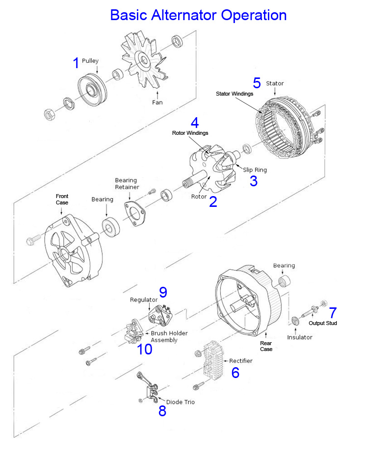
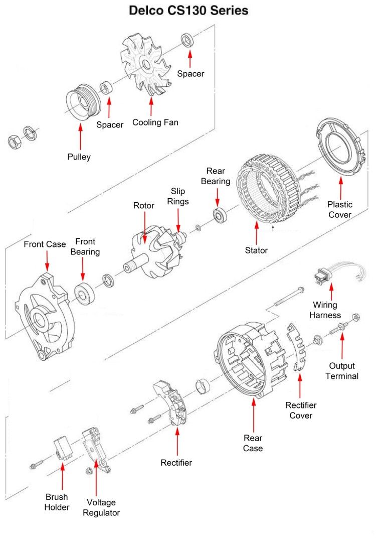
Now, the second law, which is the "converse" or "opposite" law to this one, states that: An electric current is induced in a loop of wire when the wire is moved towards or away from a magnetic field, or a magnet is moved towards or away from the wire. is precisely the principle by which an alternator works. In essence, if we could take our simple nail-and-wire electromagnet pictured above, replace the battery with a light bulb, and spin the nail inside the wire coil, we could generate an electric current to light the light bulb. That's essentially what an alternator does in the most basic sense. Basic Alternator Operation - Simple ExplanationLet's take a look at how, using an exploded diagram of an alternator. The vehicle engine's crankshaft drives a belt that in turn drives a pulley on the alternator (1). The alternator pulley (1) is fixed to the shaft of the alternator rotor (2). The rotor (2) consists of a coil of wire (the rotor windings) wrapped around an iron core. When DC electrical current is supplied through the slip rings (3) to the rotor windings (4) a magnetic field around the rotor core is produced - the rotor becomes an electromagnet. This DC current that turns the rotor into an electromagnet is called the "field current" supply - because it causes the generation of the magnetic field. We'll come back to how this field current controls alternator output shortly. Surrounding the rotor is the stator (5). The stator consists of a set of three wire coils, called the stator windings. The stator is fixed to the alternator case, and does not turn. As the names indicate - the rotor rotates while the stator is stationary. As the rotor turns within the stator, the magnetic field of the rotor sweeps through the stator windings, producing an electrical current in the windings. This current produced is 3-phase AC. It is AC because of the rotation of the rotor's magnetic field through the windings - current is produced in one direction as the North pole sweeps through the winding, and in the other direction as the South pole does. The current produced is 3-phase because of the three windings (one phase produced in each winding). This 3-phase AC power must be converted or "rectified" into single phase DC voltage to be useful. This occurs in the rectifier (6). The rectifier consists of six diodes, one pair of diodes for each winding. One diode from each pair is for the negative half of the AC cycle, and the other for the positive half of the AC cycle. Diodes have the property of allowing current to flow in only one direction, while blocking current flow in the other direction. In simple terms, the diode pairs block or "chop off" the negative halves of the AC cycles produced in the windings. As a result of this diode rectification, the output of the alternator is 12V DC, supplied to the output stud (7). Meanwhile, the diode trio (8) takes alternator output and provides it to the voltage regulator (9). The voltage regulator compares this output with reference voltage, and based on the results supplies varied amounts of field current through the brushes (10) and slip rings (3) to the rotor windings (4). The more field current that is supplied to the rotor windings, the stronger the magnetic field produced. The stronger the magnetic field, the more voltage produced in the stator windings. This voltage is then sampled by the voltage regulator, and if it is up to spec, field current is maintained. If the output voltage rises too high, the voltage regulator cuts back the field current, bringing output back into line. In this manner, the system is a closed feedback loop that self-regulates. In practice, as engine / alternator rpm drop, alternator voltage output drops which the regulator senses and as a result increases the field current to the rotor which brings the output voltage back up at this lower rpm. It works in reverse as well - higher rpm means greater voltage output. If it gets too high the regulator senses it and cuts back the field voltage, bringing the output back down. Now, if you have been following carefully, you may be left with just one question - where does the field current come from when the alternator is not yet running at speed (as in when the vehicle is first started)? Before the alternator is up to speed and generating sufficient output to be "self sustaining", the field voltage is supplied by the battery via the alternator warning lamp. This initial supplying of field current to get the alternator working is known as "exciting" the alternator. We'll go into the details of the alternator warning light and different methods of excitation a little later. So that's the simple explanation of how an alternator works. In summary:
Alternator Operation - Technical ExplanationFor those that are interested in a little more technical explanation of what is going on in an alternator, let's go over it again but this time with a little more technical detail. NOTE: This section is optional - if you're not into tech details - feel free to skip down to the next yellow heading - namely "Alternator Warning Lamp". Let's add some more detail to the material previously covered, on a component by component basis. ROTOR |
||||||||||||||||||||||||||||||||||||||||||||||||||||||||||||||||||||||||||||||
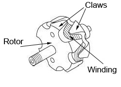 |
The rotor receives regulated voltage through a pair of brushes that bear on slip rings, and this causes it to produce a magnetic field. The rotor consists of a coil of wire (the rotor winding) wrapped around an iron core and enclosed in two multi-claw pole pieces. You can clearly see the "claws" in the picture at left. DC electrical current is supplied through a pair of brushes that bear on slip rings. The slip rings are connected to the rotor windings and thus a magnetic field around the rotor core is produced - the rotor becomes an electromagnet. |
|||||||||||||||||||||||||||||||||||||||||||||||||||||||||||||||||||||||||||||
The "claws" are actually specially shaped poles that create multiple magnetic poles from a single rotor. The rotor pictured above has six alternating pairs of poles folded back from either end. With a single revolution of the rotor, the stator windings are hit with six magnetic fields, each magnetic field having, of course, a north and a south pole just as all magnets do. |
||||||||||||||||||||||||||||||||||||||||||||||||||||||||||||||||||||||||||||||
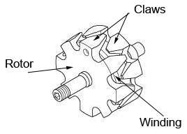 |
This rotor has 8 pairs of "claws" or magnetic poles. | |||||||||||||||||||||||||||||||||||||||||||||||||||||||||||||||||||||||||||||
STATOR |
||||||||||||||||||||||||||||||||||||||||||||||||||||||||||||||||||||||||||||||
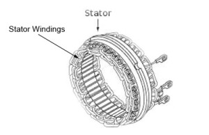 |
The stator has three sets of windings, each of which produce AC current when the rotor's magnetic field sweeps through them. In this picture you can clearly see the terminals at the ends of each of the three windings. This is known as three-phase winding. |
|||||||||||||||||||||||||||||||||||||||||||||||||||||||||||||||||||||||||||||
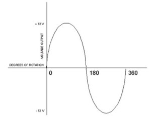
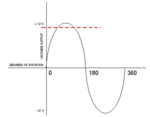
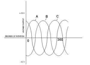
As the rotor turns within the stator, the magnetic fields of the rotor sweep through the stator windings, producing an electrical current in the windings. This current produced is an AC current because of the rotation of the rotor's magnetic field through the windings. Let's look at why this is so by first examining what happens in just one of the windings, before we consider all three together. Also note, for simplicity sake the rest of this section considers only a single magnetic field, but note that most alternator rotors actually have multiple (often 6 or 8) magnetic fields. As the north pole of the magnetic field approaches one of the stator windings, there is little electro-magnetic coupling taking place, and a weak current is produced, As the rotation continues, the magnetic field moves to the center of the winding, where maximum coupling takes place, and the induced current is at its greatest. As the rotation continues to the point that the magnetic field is leaving that stator winding, the induced current is again small. By this time, the south pole of the rotor magnetic field is approaching that winding, producing a weak current in the opposite direction, and so on. The result of this rotating magnetic field in a single winding is an alternating current (AC) that varies in voltage with the rotational position (the degree of rotation) of the rotor as it spins inside the winding. The current produced alternates back and forth between +12V and -12V as the North and South poles of the magnetic field induce current first in one direction in the winding, and then in the other direction. If we were to make a graph and plot the AC voltage for a single winding against the rotation of the rotor in degrees, it would look like this: Now, we are only interested in a small part of this output - the +12V part. So, if we filter out the rest (this is the job of the rectifier which we shall examine shortly), we end up with useful output that looks like the portion above the red dashed line in this pic: As can be seen, using a single winding like this would be very inefficient. There are long periods of time in the rotation of the rotor where the magnetic field is not producing any output that is useful to us. This is where the 3-phase winding comes in. If we were to use not one, but three separate windings, and offset them all equally we triple our useful output per rotor revolution. This is precisely how an alternator is constructed. The three stator windings are physically spaced inside the alternator 120 degrees apart, producing three separate sets, or "phases," of output voltages. The output of each winding thus occurs 120 degrees offset from the others in terms of the rotation of the rotor. If we were to plot a graph of this AC voltage for all three windings (A, B, and C) against the rotation of the rotor in degrees, it would look like this: Now, using 3-phase winding, the alternator is putting out three separate voltages, one per winding - labelled A, B, and C in the above diagram. In other words, we get triple the output for each revolution of the rotor. One practical result of this design is that the alternator can generate useful levels of current and voltage even when the rotor is spinning relatively slowly (as in idle RPM). Incidentally - an electric motor is sort of like an alternator, but opposite. Instead of something spinning mechanically to create electricity, electricity is supplied to make something spin (the motor output shaft). Ever wonder what the deal is with big electrical tools like industrial lathes - why they are all "3-phase" electrical power? The reason is the same as for the alternator, but in reverse. Running a tool's motor on 3-phase power means the output gets 3 "pushes" per revolution instead of just one. More efficient, more power. That's why the big industrial tools run on 3-phase power. It's a bit like turning a merry-go-round in a kids' playground. Single phase power would be like one person turning it - giving it one push per rotation. 3-phase power would be like 3 people spaced evenly apart (at 120° intervals) each giving it a push every rotation. But I digress. Back to the alternator... RECTIFIER |
||||||||||||||||||||||||||||||||||||||||||||||||||||||||||||||||||||||||||||||
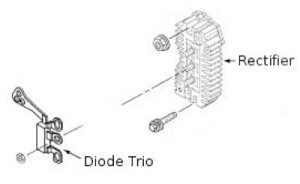 |
So, at this point the three separate stationary windings of the alternator are producing three-phase alternating current. But we need single phase DC, so the alternator must convert the 3-phase AC to DC. To do this the alternator uses a rectifier (also known as a " full-wave bridge rectifier circuit" or a "diode bridge"). The rectifier consists of six diodes - a negative and a positive for each stator coil. These are called the "output diodes", not to be confused with the "diode trio" which will be explained later. |
|||||||||||||||||||||||||||||||||||||||||||||||||||||||||||||||||||||||||||||
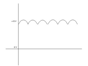
Recall that a diode is like a one-way valve for electricity. It only allows current to flow in one direction. The diodes are wired in such a way that they only conduct during half of the AC cycle, and stop conducting during the other half. The result is that the 3-phase AC is "clipped" or "filtered", resulting in DC output that looks like this: Note that this output is actually a "pulsating" or "lumpy" DC output, not a pure clean waveform. This is good enough for most automotive use, but sensitive electrical components will have or require additional filtering circuitry to "clean up" the DC for their use. This is why, for example, certain aftermarket accessories instruct you to connect them directly to the battery, because the battery acts as a giant filter or "cushion" in the system, smoothing out the DC waveform. VOLTAGE REGULATORRecall from Part 1 that the automotive electrical system can be likened to your shop air compressor system. Both are "supply and demand" systems that must be regulated for optimal performance. Take the shop air system: the compressor generates the power (the air pressure) required to fill the tank and power the air tools. The tank stores a reserve of air pressure - available for use when the compressor is not operating or to maintain adequate supply during peak demands. The regulator regulates the output to the required pressure (psi), ensuring max tool performance but without over pressurizing and damaging the air tools. And the pressure switch automatically turns the compressor on to maintain adequate psi when the system is in use, and turns it off to prevent a dangerous, uncontrolled rise in air pressure when the system is not being used. The auto electrical system works very much the same way. The alternator generates electrical power, (the voltage or "electrical pressure)) required to recharge the battery and power the electrical devices. The battery stores a reserve of electrical power - available for use when the alternator is not operating (engine off) or to maintain adequate supply during peak demands. The voltage regulator regulates the output to the required voltage, ensuring max electrical device performance but without allowing the development of high voltage that is dangerous and damaging to the electrical components. The ignition switch / exciter wire initially "turns the alternator on" when the system is first started. If the alternator was allowed to constantly produce all the power it could, system voltage would rise to a damaging level, the battery would overcharge, components would be damaged, and the alternator would soon overheat and burn out. Conversely, if the alternator is not functioning the battery will try and supply all the electrical current, voltage will steadily drop, and eventually the battery will become completely discharged and the car no more worky! |
||||||||||||||||||||||||||||||||||||||||||||||||||||||||||||||||||||||||||||||
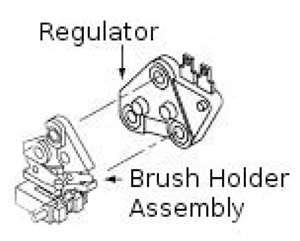 |
It is the job of the voltage regulator to balance the supply and demand of the electrical system by regulating the alternator output. |
|||||||||||||||||||||||||||||||||||||||||||||||||||||||||||||||||||||||||||||
If the battery is fully charged and we have no lights or other electrical accessories operating, very little voltage need be produced by the alternator (there will always be at least some demand due to voltage drop in the system wiring, caused by the resistance of the wire itself - remember Ohm's law!) However, if we have lights, electric fans, a weak or partially discharged battery, and a big stereo playing, system demand will be high and the alternator will be required to produce much greater output to keep things in balance, charge the battery, and prevent system degradation or malfunction caused by low voltage (e.g. dim lights). We'll look at an example using some real numbers shortly. Now, the output of any given alternator is primarily determined by the rotational speed (RPM) of the rotor and the strength of the magnetic field produced by the rotor. In turn, the strength of the magnetic field produced by the rotor depends on the amount of current (the field current) supplied through the brushes and slip rings to the rotor windings. It is this field current that the voltage regulator controls, or regulates, in order to control alternator output voltage across all alternator speeds (RPM). Today, virtually all alternators used internal solid-state (also known as electronic or transistor) voltage regulators. The regulator has two inputs and one output. The inputs are the field current supply and the control voltage input, and the output is the field current to the rotor. We will examine the concept of the control voltage input in some detail in the section on wiring. For now, it is sufficient to think of it as a wire from the battery or main electrical distribution block that provides a constant "reading" of system voltage to the regulator. The regulator uses this control voltage input to control the amount of field current input that is allow to pass through the brushes and slip rings to the rotor windings. If the system voltage drops (e.g. when lights are turned on or engine rpm decreases) the regulator senses this and allows more field current to reach the rotor, which increases the magnetic field strength, which ultimately increases the voltage output of the alternator which brings the system voltage back to the correct level. Conversely, if the system voltage goes up (electrical devices are shut off, or engine rpm increases), the regulator allows less field current through to the rotor windings, and the alternator output voltage is reduced, again bringing the system back into balance. It's a closed-loop feedback system and it works extremely quickly and reliably so that the end result is almost entirely consistent system voltage regardless of electrical load or engine RPM. The regulator uses transistors to control the field current. A transistor is a device used to amplify and switch electronic signals. It is composed of a semiconductor material with at least three terminals for connection to an external circuit. A voltage or current applied to one pair of the transistor's terminals changes the current flowing through another pair of terminals. When system demand causes a voltage drop (the control voltage input is less than nominal) the regulator senses this and a small current is sent to a transistor which amplifies it and sends it to another transistor which acts as a valve in controlling the flow of the field current input to the rotor. Field Current SupplyThe field current supply is provided from one of two different sources, depending on the state of the alternator. When the engine is not running and the alternator is not spinning and producing electricity, the field current supply comes from the vehicle's battery, via the ignition switch and alternator warning lamp (if equipped). We'll go into more detail on the warning lamp shortly. The process of supplying battery voltage to "kick-start" or "prime" the alternator is known as "exciting" the alternator, and the wire that carries the current from the alternator warning lamp to the appropriate voltage regulator terminal is known as the "exciter" wire. A few special alternators do not have this wire and are known as "self-exciting" - we'll cover this in more detail in the wiring section. After the engine is started, and the alternator is generating electricity the diode trio feeds the alternator output back to the voltage regulator to serve as the field current supply. Theoretically, once up to speed, the alternator is self sustaining, and the car will run without a battery until it is shut off (as long as system demand does not exceed alternator output capacity). However - you should never disconnect the battery in a running vehicle as doing so can cause voltage surges that can damage not only the voltage regulator, but also other on-board electrical equipment - particularly computer-controlled devices. Remember the diagram of the pulsed DC output from the alternator and the fact that the battery acts as a large filter or cushion in the system. Note that the field current is much smaller than the output current produced in the stator windings. For example, to produce 70 amperes of DC, the field current required will be less than 2 amperes. The NumbersAs mentioned in Part 1 - one thing most of us already know is that automotive electrical systems are 12 Volt DC. BUT - it is important to note that TWELVE volts is just a nominal voltage. Although we always refer to the related circuits and components as "12 Volt", in reality a typical, fully charged automotive battery will produce 12.6 volts (with the engine off) and the alternator's voltage regulator will be set to maintain system voltage at somewhere between 14.0 - 14.6 volts, with 14.2 volts normally being considered "optimal". To understand why the voltage regulator is set to 14.2 volts, recall that one of the jobs of the alternator is to recharge the battery, and remember that voltage is "electrical pressure" and therefore flow (current) will only occur when there is a "pressure difference" or voltage difference between two points. As such, if the regulator were set to maintain alternator output (and therefore system voltage) at 12 volts, no voltage difference would be present between alternator output and battery, and therefore no current would flow between alternator and battery and as a consequence the battery would not charge until it fell below 12 volts - and by then it is already partially discharged. As it turns out, a healthy, fully charged “12volt” battery produces about 12.6 volts. Alternator output must therefore exceed 12.6 volts for electrical current to continuously flow through the battery, which is what charges it. A detailed explanation of battery charging is beyond the scope of this article, but basically in order to charge a battery an electrical current must flow through it as this enables the chemical reaction required between the liquid acid and the lead plates in the battery. And it turns out that 14.2 volts is the required voltage to create the optimal current to continuously charge a 12 (12.6) volt automotive battery. In summary, we see that the voltage regulator is the "brains" of the alternator and indeed the entire vehicle's charging and electrical system. It also holds quite a lot of potential for tinkering or modification, although we won't be getting into that here. But the devout hackers and tweakers amongst you will no doubt have already realized that by modifying the voltage regulator, or even purchasing a custom-built unit, an alternator can be set up to produce almost any voltage up to about 130 volts. Not only that, but modifying the rectifier can also allow the alternator to output 60HZ AC power for powering electric tools, welders, and all sorts. These modifications are indeed what is at the heart of special alternators that are manufactured and marketed as 120V 60Hz power sources (i.e. standard North American household power). ALTERNATOR WARNING LAMP |
||||||||||||||||||||||||||||||||||||||||||||||||||||||||||||||||||||||||||||||
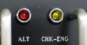 |
Far from being an "idiot light", the alternator warning lamp can tell us a great deal about the health of our alternator and other electrical components if we understand how it functions. | |||||||||||||||||||||||||||||||||||||||||||||||||||||||||||||||||||||||||||||
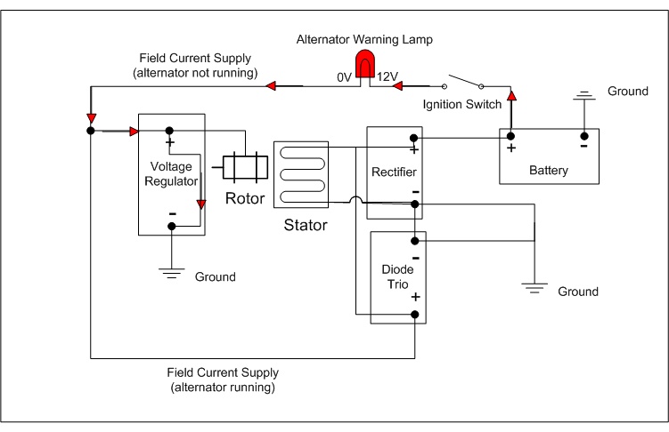
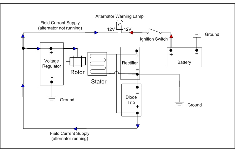
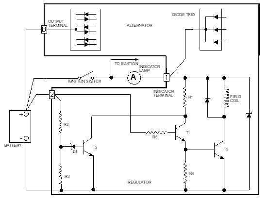
The alternator warning lamp is connected in series between a switched ignition source (the field current supply) and the voltage regulator. The voltage regulator is also connected to ground. When the ignition switch is closed (the ignition key is turned on), current flows from the battery, through the alternator warning lamp, through the voltage regulator to ground. As such, the alternator warning lamp glows. In the following simplified block diagram (not a real electrical schematic), when the alternator is not running, the battery provides the field current supply (red arrows) and the lamp is grounded and therefore glows. As we know, after the engine is started, and the alternator is generating electricity the diode trio feeds the alternator output back to the regulator to serve as the field current supply. This equalizes the voltage across the alternator warning lamp (there is no longer a path to ground for the lamp), current stops flowing through the lamp, and therefore the lamp goes out. Remember from Part 1 - in order for the lamp to glow, there must be current flow through it - and in order for current to flow - there must be a voltage difference (pressure difference) across the lamp. In effect, the alternator output equalizes the pressure coming from the ignition switch and stops the current flow. In the following simplified block diagram (not a real electrical schematic), when the alternator is running, the diode trio feeds alternator output back as the field current supply (blue arrows) which equalizes voltage across the lamp and therefore it does not glow. So, now we know, anytime the alternator warning lamp is on, it means there is a voltage difference across it. That means that either: 1) the battery voltage is higher than the alternator output, or that 2) the alternator output is higher than the battery voltage. In the case of (1), it probably means that the alternator is weak or failing. In the case of (2), it probably means that the battery is weak or discharged. How can we tell which it is? Simple - if we apply our new knowledge of how an alternator works, we can easily determine which is the problem. Recall that alternator output is dependant on alternator RPM. If we increase alternator speed, we increase alternator output. Therefore, if we rev the engine, we increase alternator speed and output, and if as a result the light gets dimmer it means the alternator output was weak (it must be increased by revving the engine to try and equalize the voltage across the lamp). If, however, the lamp gets brighter when we rev the engine, it means the battery voltage is low. This is because battery voltage does not vary with RPM. Therefore, if an RPM increase causes an increase in lamp brightness, it can only be because the increasing alternator output is getting even higher than the battery voltage. With a healthy battery, this won't happen - battery voltage will match alternator output. But if the battery is unable to take or hold a full charge, the more we increase the alternator output the more it exceeds the weak battery voltage and the brighter the lamp will glow. In summary, we can say that:
Of course, these are just basic guidelines as wiring faults and bad grounds can cause all manner of electrical faults that sometimes appear to be other things. A Look InsideLet's take a look now at the parts inside an actual alternator. This particular unit is an older GM Delco-Remy CS-130 series alternator. |
||||||||||||||||||||||||||||||||||||||||||||||||||||||||||||||||||||||||||||||
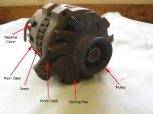 |
Front 3/4 view. | |||||||||||||||||||||||||||||||||||||||||||||||||||||||||||||||||||||||||||||
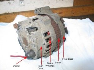 |
Rear 3/4 view. | |||||||||||||||||||||||||||||||||||||||||||||||||||||||||||||||||||||||||||||
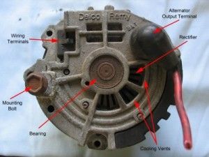 |
Rear view. | |||||||||||||||||||||||||||||||||||||||||||||||||||||||||||||||||||||||||||||
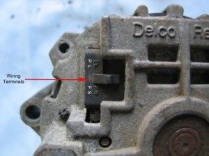 |
The wiring terminals on this model are small pins inside this plastic female plug. Wiring terminals are connected to the voltage regulator. |
|||||||||||||||||||||||||||||||||||||||||||||||||||||||||||||||||||||||||||||
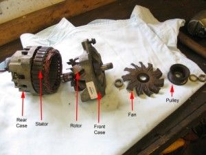 |
Here I have removed the nut holding the pulley on the rotor and have begun to disassemble the alternator. | |||||||||||||||||||||||||||||||||||||||||||||||||||||||||||||||||||||||||||||
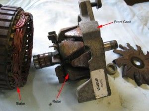 |
Front parts. | |||||||||||||||||||||||||||||||||||||||||||||||||||||||||||||||||||||||||||||
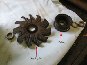 |
There are many different fan and pulley designs used on Delco-Remy alternators. |
|||||||||||||||||||||||||||||||||||||||||||||||||||||||||||||||||||||||||||||
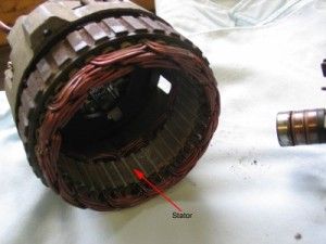 |
The rear case houses the stator. | |||||||||||||||||||||||||||||||||||||||||||||||||||||||||||||||||||||||||||||
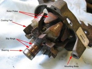 |
Rotor and associated parts. | |||||||||||||||||||||||||||||||||||||||||||||||||||||||||||||||||||||||||||||
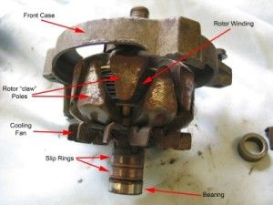 |
Rotor and associated parts. | |||||||||||||||||||||||||||||||||||||||||||||||||||||||||||||||||||||||||||||
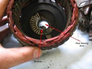 |
Looking inside the rear case with the stator in place. You can see the spring-loaded brushes which bear against the slip rings on the rotor, and the bore in the back of the rear case where the rear bearing goes. Note the rough (broken) condition of the brushes. |
|||||||||||||||||||||||||||||||||||||||||||||||||||||||||||||||||||||||||||||
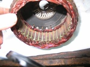 |
Here we can see the three stator winding outputs passing through a black plastic cover to the rectifier. | |||||||||||||||||||||||||||||||||||||||||||||||||||||||||||||||||||||||||||||
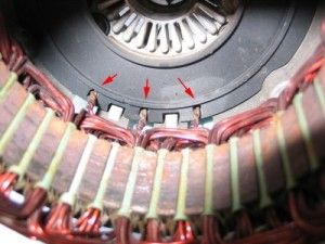 |
Close up of the three stator winding outputs | |||||||||||||||||||||||||||||||||||||||||||||||||||||||||||||||||||||||||||||
| . | ||||||||||||||||||||||||||||||||||||||||||||||||||||||||||||||||||||||||||||||
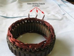 |
Stator removed from the rear case. As it happens, the CS-130 series are some of the least desirable alternators as they were built to be throw-away units and are not really rebuildable. That's why the stator windings are cut in this picture instead of having terminals on them. |
|||||||||||||||||||||||||||||||||||||||||||||||||||||||||||||||||||||||||||||
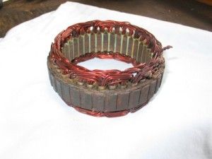 |
Notice the copper wire of the stator windings goes in threes. | |||||||||||||||||||||||||||||||||||||||||||||||||||||||||||||||||||||||||||||
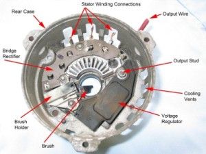 |
Looking into the rear case with the stator and black plastic cover removed. | |||||||||||||||||||||||||||||||||||||||||||||||||||||||||||||||||||||||||||||
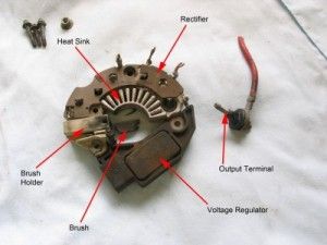 |
The "brains" of the alternator removed from the rear case. Note that this model doesn't have a separate diode-trio, but functions the same as we have described; with the rectifier also doing the diode-trio's job. |
|||||||||||||||||||||||||||||||||||||||||||||||||||||||||||||||||||||||||||||
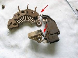 |
Note the two electrical connections - one between rectifier and regulator; and one between brush holder and regulator. Again, note that these connections are crimped and soldered and were never intended to be serviceable. |
|||||||||||||||||||||||||||||||||||||||||||||||||||||||||||||||||||||||||||||
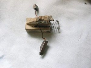 |
Brush holder. It's pretty much the same as the brush holder in any electric power tool. |
|||||||||||||||||||||||||||||||||||||||||||||||||||||||||||||||||||||||||||||
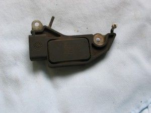 |
Voltage regulator. No serviceable parts on this model. |
|||||||||||||||||||||||||||||||||||||||||||||||||||||||||||||||||||||||||||||
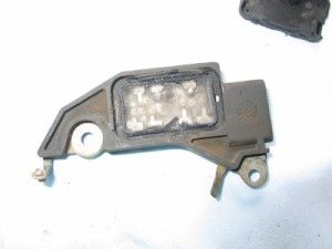 |
But if you pry (break) off the cover, inside you can see the transistors surrounded by a jelly-like goo. | |||||||||||||||||||||||||||||||||||||||||||||||||||||||||||||||||||||||||||||
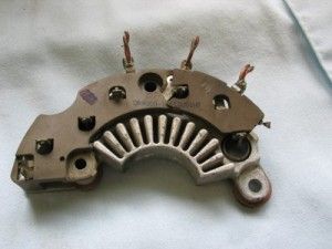 |
The bridge rectifier unit. Note the large aluminum heat sink and the three cut connections at the top (that used to be hard-wired to the stator windings). |
|||||||||||||||||||||||||||||||||||||||||||||||||||||||||||||||||||||||||||||
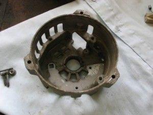 |
The empty rear case. | |||||||||||||||||||||||||||||||||||||||||||||||||||||||||||||||||||||||||||||
Here's an exploded diagram of the alternator pictured above: |
||||||||||||||||||||||||||||||||||||||||||||||||||||||||||||||||||||||||||||||
Common GM Delco-Remy AlternatorsThere are dozens of different brands of alternator out there - AC Delco, Delco-Remy, Bosch, Carrier, Champion, Mitsibushi, Prestolite, Ford, Hitachi, Motorola, Nippondenso, Thermo King, Wilson, and many others. Obviously there's no possible way I can cover them all. One of the most common brands / types out there are the GM / AC Delco / Delco-Remy alternators used on tens of millions of GM cars and light trucks. These units are simple, rugged, good performing, mostly rebuildable, and available virtually anywhere and everywhere. They make good candidates for swapping into everything from hot rods to custom 4x4 buggies. They are also available in a huge variety of series and styles in different sizes, performance ratings, and price brackets. Chances are, if you had to pick one type - this would be the one with the greatest chance of having a model or part number to fit your needs. As such, when confronted with limited space and time, it makes sense for us to cover these alternators. There are two broad "series" of GM Delco-Remy alternators built since 1971. Both have internal voltage regulators (very early alternators used external voltage regulators but they are now old, rare, and not really suitable for off-road use). The early type, called the "SI" series, were used in GM cars and trucks from about 1971 to about 1986, and are still available today through Delco-Remy, various rebuilders, and the aftermarket. The SI stands for Systems Integrated and they are so-called because they were the first Delco-Remy alternators to be built with internal, or integrated, voltage regulators. The later type, called the CS series, were used in GM cars and trucks from about 1986 to the present. The CS stands for Charging System (the creative names department must have been closed that day!). The most common types in each series are as follows: SI Alternators |
||||||||||||||||||||||||||||||||||||||||||||||||||||||||||||||||||||||||||||||
 |
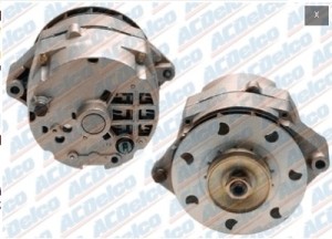
Delco-Remy 10-SI Series1971 - 1985 - First GM internal voltage regulator alternator - Used extensively on GM cars & light trucks and other applications such as marine and agricultural. - Available in outputs from 37 - 72 amps, with 40 amp, 63 amp, and 72 amp being the most common. |
|||||||||||||||||||||||||||||||||||||||||||||||||||||||||||||||||||||||||||||
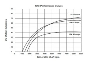 |
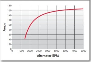
Typical 10-SI performance curve plotting alternator output in amps vs. alternator rpm. | |||||||||||||||||||||||||||||||||||||||||||||||||||||||||||||||||||||||||||||
 |
Delco-Remy 12-SI Series1983 - 1986 - The 12-SI was an update and improvement on the 10-SI design. - The 12-SI has the same outside dimensions as the10-SI but with several design improvements for better performance, including:.
- Available in outputs from 56 - 94 amps, with 78 amp and 94 amp being the most common. |
|||||||||||||||||||||||||||||||||||||||||||||||||||||||||||||||||||||||||||||
If you look at the above photos of the 10-SI and the 12-SI, you will notice that the two easiest ways to visually distinguish between the two are 1) The style of fan installed and 2) The much larger air vents in the back of the 12-SI. The latter is the best feature to use, as it is always possible that someone swapped fans - but in stock form the fans are clearly easy to tell apart. The 10SI and 12SI are Delco Remy model series designations - not part numbers. Each was built in several different output ratings, and assembled with any one of four available “clock” positions for different mounting bracket arrangements. Add to that the different types of pulleys that could be installed and the result is obviously many different part numbers. The "clock position" of an alternator refers to the location of the electrical terminals with respect to the threaded mounting hole. If you view the alternator from the back, with the threaded mounting hole at the top (12 'o' clock position) then the location of the terminals in terms of "clock face position" is the "clock position of the alternator. The following picture illustrates a 10-SI alternator with "12 'o' clock" clock position. If the terminals were to the right side, it would be a "3 'o' clock" alternator. Straight down opposite the threaded hole would be 6 'o' clock, and so on. Having the different available clock assembly positions allows for exit of the wiring from the alternator in the direction required for use with different mounting setups. SI series alternators are an older design, but they make excellent candidates for use in off-road vehicles that don't have huge electrical demands. They are cheap, plentiful, rugged, reliable, very easy to diagnose, repair, and rebuild and parts for them are still available nationwide. Unlike some later design, virtually any individual part in an SI series alternator can be easily replaced - they were built to be serviced - something that is not always true for later designs. CS AlternatorsFirst produced in the mid-1980's, Delco-Remy CS series alternators are probably the most numerable on the planet. The following are the most common: |
||||||||||||||||||||||||||||||||||||||||||||||||||||||||||||||||||||||||||||||
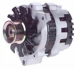 |
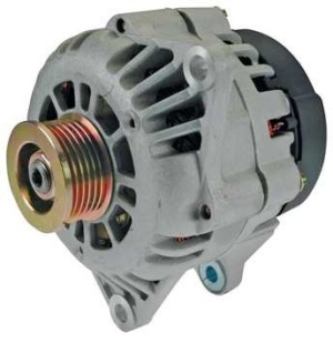
Delco-Remy CS-121 & CS-130 Series1986-1996 In 1986, the CS-121 and CS-130 alternators were a complete design departure from the SI series alternators they were designed to replace. Designed to produce high ampere output per pound of weight, they featured a new and different voltage regulator, different terminals, and no diode trio. |
|||||||||||||||||||||||||||||||||||||||||||||||||||||||||||||||||||||||||||||
In stock trim they are available in the following outputs:
They certainly produced good output per pound, but there were a couple of design elements that make them a poor choice. First, by packing high performance in a small case - they tend to get hot, and heat leads to breakdown and malfunction . This is compounded by the fact that the units were designed to be either "maintenance free" or "throw-away units incapable of being repaired", (depending on your outlook). The 121 and 130 are visually nearly identical, and share the same design, but the 130 is slightly larger than the 121. In fact, the numbers 121 and 130 denote the outside diameter, in millimeters, of the stator ring. |
||||||||||||||||||||||||||||||||||||||||||||||||||||||||||||||||||||||||||||||
 |
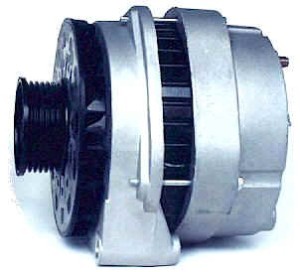
Delco-Remy CS-130D Series1994-2000 In the mid 1990's the CS-130D took over as the standard application alternator on most GM vehicles. In stock trim it offered 100-105 amp outputs. Don't let the name fool you, although it had "CS-130" in its name, the CS-130D was a completely different unit from the earlier CS-130. Design improvements from the earlier CS-130 include:
|
|||||||||||||||||||||||||||||||||||||||||||||||||||||||||||||||||||||||||||||
| This last feature is one of the more readily identifiable features of the CS-130D alternator, as can be seen in the picture above. Notice how the black plastic housing that contains the regulator and rectifier sticks off the back of the rear case. | ||||||||||||||||||||||||||||||||||||||||||||||||||||||||||||||||||||||||||||||
 |
Delco-Remy CS-144 Series1986-2006 The CS-144 series alternators are physically larger, higher-output alternators used during the same period as the CS-130 and CS-130D. Early models were 108-124 amp and later versions 124-145 amp output. Despite their larger size, the mounting bolt pattern is the same as for the CS-130 and CS-130D, so if you have the room they can make an easy swap. The larger size of the CS-144 offers a reliability increase as the extra mass is better able to absorb and dissipate the heat generated when making 100 amps or more. |
|||||||||||||||||||||||||||||||||||||||||||||||||||||||||||||||||||||||||||||
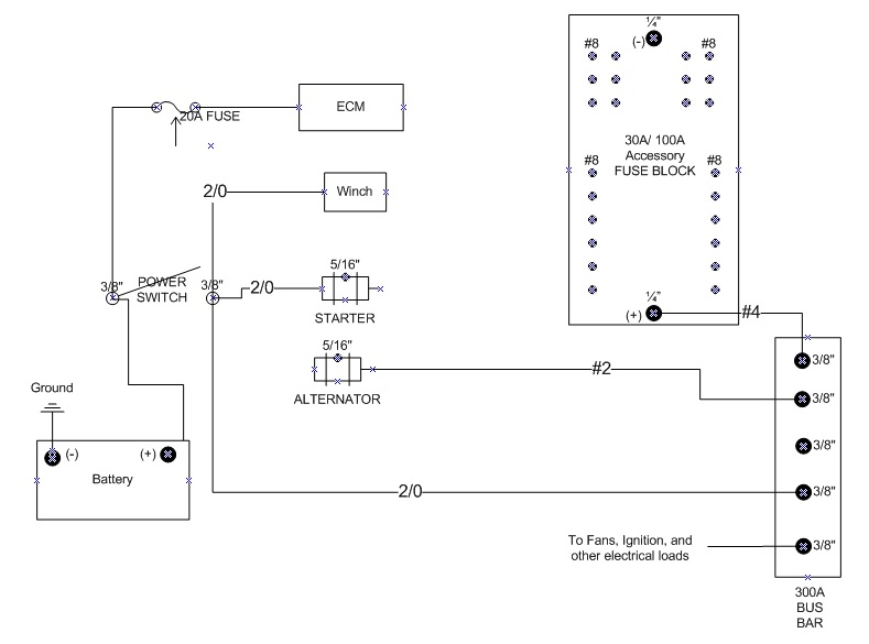
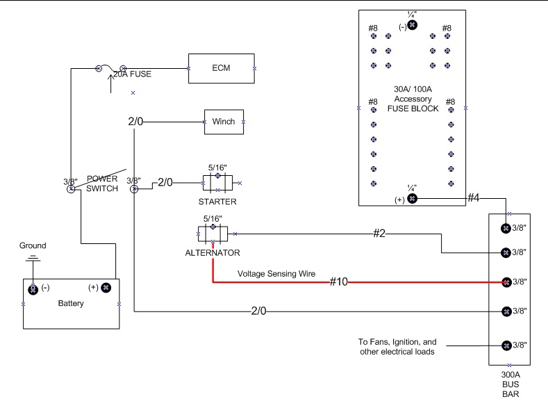
WiringOK, now we're getting down to it! Probably the most frequently asked question with regards to alternators is: "How do I wire this alternator?" It should be an easy question to answer, but sadly it isn't always that simple. There are thousands of different alternators in use and available on the market - made by American, Asian, and European companies. There are equally as many different vehicle wiring systems. On top of that - there is a distinct lack of standardization in the industry with respect to things like the name, location, and function of the different connections or terminals on alternators. The result can be a confusing mess - or at the very least leaves us with a situation a little more complicated than "unplug this unit and plug this one in in its place"! Obviously, I can't possibly cover every alternator, engine, and wiring harness combination - can't even begin to scratch the surface really. That's why we've covered so much detailed tech so far in this article - so that you can understand how things work, and puzzle out answers and solutions for yourself - or at the very least stand a good chance of determining if what you read on the internet makes sense. 1 wire, 2 wire, 3 wire, 4There can be much confusion when discussing different types of alternators base on the designation "1 wire" or "2 wire" or "3 wire", etc. There is a simple reason for this confusion which I hope we can clear up. From our description of how an alternator works, it should be clear that all alternators require a minimum of four "elements" to operate - 1) Field Current, 2) Voltage sensing, 3) Ground, and 4) Output. The trouble is, there are multiple designs that use different methods of providing these four "elements", and they use different numbers of wires in doing so. What complicates the matter is that: a) The number of wires does not always correlate on a 1:1 basis with the required "elements", and b) Some designs use additional wires for "optional" features and these wires may or may not be included in the count when someone describes an alternator as "2-wire" or "3-wire" etc. So, there are different designs with different numbers of wires, but ALL must have the four "elements" to operate - 1) Field Current, 2) Voltage sensing, 3) Ground, and 4) Output. For example, the so-called "1-wire" alternator, even though it does indeed have only a single wire connecting the output terminal to the battery, still has the four "elements". But, many self-exciting alternators (so-called 1-wire) can be (and often are) hooked up using two wires - the bat cable for elements (2) and (3), and an additional excitation wire for initial field current supply (i.e. they can self-excite, but they can also use an excitation wire). So would this be a "1-wire alternator", a "2-wire alternator", or a " 1-wire hooked up with 2 alternator"? Then there are those alternators that come with a dedicated grounding terminal (as opposed to just grounding through the case / mounting bracketry). Does this "wire" get included in the wire count? And if that wasn't enough - what do you call an alternator that has four terminals on the voltage regulator (S F L P ), a Bat terminal, and a dedicated ground terminal? Is that a 6-wire alternator? What if it's hooked up with wires going only to the Bat, Ground, and L terminal? Does it "become" a 3-wire alternator now? It gets confusing. As such, I prefer to avoid referring to alternators by "wire number" as that is clearly not a definitive way of delineating how the alternator operates (and therefore how it should be hooked up). Instead, in terms of "number of wires", I will differentiate only between two groups - the self-exciting or "one wire" alternator and then all other non-self-exciting or "multi-wire" alternators. Then I'll break down the multi-wire alternators by the terminals they have. But first, we must briefly discuss the concept of voltage sensing in a little detail. Voltage SensingOf the four "elements": we have already discussed field current in detail. Output and ground are self-explanatory. Which leaves only voltage sensing requiring a little more explanation. We have already discussed briefly why voltage sensing is required - recall that it is the method by which the voltage regulator senses system voltage and compares the result to its internal setting, and based on the results of that comparison either increases or decreases alternator output. The "internal setting" is built into the voltage regulator and is the system voltage the regulator will try and maintain. Internal settings may differ slightly between voltage regulators but all are about 14.0 volts. The concept is simple, but there is a nuance that is important. Because voltage is like "electrical pressure", and because there is some resistance in all components in a circuit - even the wires themselves - it should be fairly easy to see that it matters where the "system voltage" is sensed. Let's examine why with an example, using the following basic system design block diagram: Here we have the battery, connected through a master disconnect switch to three things: 1) Winch, 2) Starter Motor, and 3) Main Electrical Distribution point (labelled "300A Bus Bar" in the diagram). This system design is practical, easy to work with, convenient, and offers good performance, especially when electrical components are spread out throughout the vehicle (ignition,radiator fans and radios near the front, fuel pumps, cooler fans, and amplifiers near the back, etc.) It is the preferred method of electrical distribution - i.e. having a main bus bar or electrical distribution point. This main distribution point feeds all the vehicles electrical systems as well as receiving alternator output and either passing charge to the battery or accepting current from the battery (depending on whether the alternator is running or not). OK, with this system, let's assume the alternator's voltage regulator is "set" to 14.0 volts. If we "sense" system voltage (i.e. hook up the alternator's voltage sensing terminal) right at the alternator output , we are going to get a value equal to the alternator's output (obviously) - say 14.0 volts. Now, the voltage regulator says to itself "I'm supposed to produce an output sufficient to maintain system voltage at 14.0 volts. I sense system voltage (at my output terminal) as 14.0 volts. Everything OK, maintain this level of output." Meanwhile - 12 feet away the power-hungry amplifiers are only getting 13.0 volts because of the voltage drop that occurs in the wiring from the alternator to the main bus bar and on to the amps. It's even worse for components further "downstream" from the bus bar. But the alternator has no way of knowing this - because we hooked the voltage sensing wire right to the alternator output - it thinks everything is fine, it thinks system voltage is at 14.0 volts and it has no idea about the low voltage at the amps. Doing this - sensing voltage at the alternator output - seriously hamstrings the system - it's like a self-fulfilling system - it's supposed to maintain 14.0 volts, it outputs 14.0 volts, therefore everything must be OK, right? But it completely ignores voltage drop in the rest of the system - and that's bad for performance (incidentally, many electrical components, when experiencing as little as a10% drop in voltage supply can experience a 30% drop in performance!) Remote Voltage SensingThis is where the concept of REMOTE voltage sensing comes into play. Instead of sensing system voltage at the alternator or close to it (which is like congratulating yourself on a great job regardless of the results!) - we sense system voltage where we need full voltage - in this case at the main distribution point (bus bar). That way, when the voltage sensing circuit detects 13.0 volts at the main bus bar, it says: " I'm supposed to produce and output sufficient to maintain system voltage at 14.0 volts. I sense system voltage as 13.0 volts. Better increase output to 15.0 volts to bring system voltage up to 14.0 volts." Such a system would look like this (note the remote voltage sensing wire, highlighted red): Another advantage to this remote voltage sensing, is that it allows the alternator to compensate for increased system demand as more accessories are turned on. That's what it's supposed to do, after all. As more and more devices are switched on, a voltage drop will occur at the main bus bar. With remote voltage sensing, the alternator sees this drop caused by the extra demand, and automatically increases output to compensate. To not use remote voltage sensing, or to simply jumper the wire to the alternator output or some other nearby source would be like hiring a blind sniper - sure you might hit the target, but only by blind luck! Now - if you're thinking about what I've just written and looking at the diagram and thinking: "But why do I need that #10 GA wire for voltage sensing? I already have that big fat #2 wire going from the alternator to the bus bar - why not just jumper that to the voltage sensing terminal?" well, all I can say is I am soooooo disappointed in you! ;-) Have you forgotten Part 1 so quickly? Remember voltage is the "electrical pressure" difference between two points and that voltage is related to current flow and resistance. In the diagram above - as system demands draw more and more current, so the voltage at the bus bar will drop. However, if we take our voltage sensing directly from the alternator output, we will only be reading alternator output not system voltage, despite the fact that the #2 wire connects to the bus bar - the current is flowing from the alternator output to the bus bar, not the other way around, and it is "losing pressure" as it goes. If we just jumper the #2 wire to the voltage sensing terminal, we are reading the "pressure" at the beginning of its journey, and yet we know it decreases as it goes. On the other hand, the advantage to the #10 voltage sensing wire is that very, very little current flows through it, and this doesn't vary with system demand (i.e. when we switch more stuff on) AND it is sensing the voltage at the END (or at least the middle) of its journey, which is what is important to us. Also, note that connecting the remote voltage sensing terminal to the battery will only result in the alternator being a good battery charger - it still won't compensate for voltage drop in the system caused by wiring to the main distribution point and increasing electrical demand as more components are powered on. Also note that this "main distribution point" system only works properly when the “battery charging wire” connects from the main distribution point to the battery (as seen in the diagrams above). There should never be a wire connected from the alternator directly to the battery. This is because, the voltage regulator can only "sense" and "respond to" one voltage - in this case the voltage at the main distribution point. If we also ran a heavy gauge charging wire from the alternator directly to the battery, we risk dangerously overcharging the battery as the alternator adjusts output to maintain the main distribution point at 14.0 volts. That's why the battery must also take its charge from the main distribution point - so the system is in equilibrium and we don't risk sending 16.0 volts directly to a battery because that's what the alternator is outputting to keep the main distribution point at 14.0 volts. Before we move on, here are some quick pics of some of the actual components used in the above type of system design (based on the system in my buggy). We'll cover these in more detail in Part 3 of the series. |
||||||||||||||||||||||||||||||||||||||||||||||||||||||||||||||||||||||||||||||
 |
Odyssey battery. | |||||||||||||||||||||||||||||||||||||||||||||||||||||||||||||||||||||||||||||
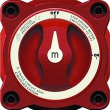 |
Marine main battery switch. | |||||||||||||||||||||||||||||||||||||||||||||||||||||||||||||||||||||||||||||
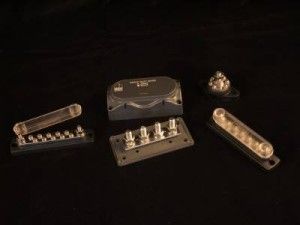 |
Marine power distribution blocks. The "main" 300A bus bar is in the middle. | |||||||||||||||||||||||||||||||||||||||||||||||||||||||||||||||||||||||||||||
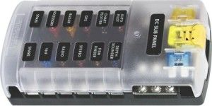 |
Marine fuse panel. | |||||||||||||||||||||||||||||||||||||||||||||||||||||||||||||||||||||||||||||
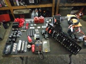 |
The marine main power switches (one for (+) and one emergency switch for ground) are top centre. The main bus bar is at the lower left of the pic, the fuse panel lower middle, with various other bus bars between them. |
|||||||||||||||||||||||||||||||||||||||||||||||||||||||||||||||||||||||||||||
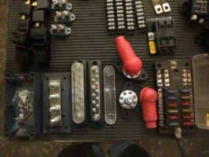 |
Bus bars and fuse panel. | |||||||||||||||||||||||||||||||||||||||||||||||||||||||||||||||||||||||||||||
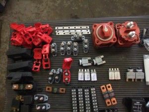 |
Main power switches, top right. | |||||||||||||||||||||||||||||||||||||||||||||||||||||||||||||||||||||||||||||
OK, so now that we've covered voltage sensing, we're ready to move on to the two different alternator types (in terms of wiring) - 1) self-exciting and 2) Non-self-exciting. Self-exciting alternatorsThe so-called "one wire" alternator is actually a self-exciting alternator. This design has one advantage and many disadvantages - which we shall cover shortly. However, let me get it out there up front - because of the many disadvantages, I personally would not recommend anyone use a self-exciting alternator - there are just too many drawbacks. How it worksThe short answer is, of course: "The same way every other alternator does." The real question is - how does it get the four "elements" using only a single wire? Here's how: 1) Field Current Instead of a dedicated wire supplying field current to excite or "start" the alternator, this design is "self-exciting". It uses a special voltage regulator that senses alternator RPM and when it is low (as in when starting the engine) it uses the residual magnetism in the alternator's rotor fields to supply the initial field current until the alternator comes up to speed and alternator output takes over as the field current supply. Remember when we discussed the different types of magnets, we talked about permanent magnets and electromagnets? And we said that a permanent magnet gets its magnetism because of the material from which it is made? We then talked about how the rotor of an alternator, having an iron core with field windings around it, is an electromagnet. Well, because the rotor has an iron core, if it is initially magnetized during construction (which it is), then the core alone is a permanent magnet, even without the windings (albeit a comparatively weak one). Therefore, if we rotate the rotor iron core permanent magnet inside the stator windings we produce an electrical current - again, a weak current (not enough to supply the vehicle's demands) but it IS enough to excite the alternator. So what happens with the self exciting alternator is that the rotor, as a permanent magnet, when turned inside the stator windings, is able to supply just enough current to the voltage regulator for the voltage regulator to supply back to the rotor windings as field current, which "turns on" the rotor as an electromagnet, and we're off to the races. Of course, since the initial "permanent magnet" output is weak, the rotor has to be spun fast enough to produce enough current to supply the field windings - which is why sometimes in a vehicle with a self-exciting (one-wire) alternator you have to rev the engine initially to get the alternator working and the ALT WARN lamp to go out! 2) Voltage Sensing Instead of a dedicated voltage-sensing wire, a self-exciting alternator uses the main battery wire for voltage sensing. We've already discussed the serious limitation this creates. 3) It grounds through the case / mounting brackets to the engine block. so there is no dedicated grounding wire. This is typical of many non-self exciting alternators too, so nothing special here. 4) It uses the main battery wire for output. Again, nothing special here, so do all non-self exciting alternators. AdvantagesThe only real advantage to a self-exciting (one-wire) alternator is that it is very easy to wire - obviously. However, in my humble opinion its many drawbacks mean it is suitable only for a diesel tractor with no electrical system whatsoever other than a starter motor! DisadvantagesThere are several serious disadvantages to a self-exciting (one-wire) alternator, including:
Non-self-exciting alternatorsBy far the better performing and more suitable group of alternators are the non-self-exciting (or multi-wire) alternators. For GM / Delco-Remy alternators these can be broken down into two sub-groups in terms of wiring / terminals that conveniently (for once!) correlate with the Delco-Remy series they belong to. SI Series / 2-terminal AlternatorsTerminalsThe older 10-SI and 12-SI series alternators are also sometimes (somewhat inaccurately) known as either two-terminal alternators (after the 2 terminals commonly found on the voltage regulator), or three-wire alternators (after the most common configuration that uses three wires - one to each of the common voltage regulator terminals plus the output wire to the Bat(+) terminal). |
||||||||||||||||||||||||||||||||||||||||||||||||||||||||||||||||||||||||||||||
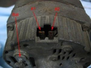 |
This is a 12-SI alternator with the so-called "2-terminal" configuration. As you can see, there are actually three terminals, as follows:
|
|||||||||||||||||||||||||||||||||||||||||||||||||||||||||||||||||||||||||||||
The functions of the terminals are as follows:
So far, so good - but if we look a little closer, things get a wee bit confusing on this so-called "2-terminal" alternator |
||||||||||||||||||||||||||||||||||||||||||||||||||||||||||||||||||||||||||||||
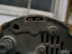 |
As we can see, in addition to the labels for the #1 and #2 terminals, this case has three other labels - two R's and an F. This is because the terminal labels are cast on the rear case, the cases are mass produced, and that some of the terminals are optional (i.e. whether they are present or not depends on the voltage regulator installed in the alternator – and one rear case may be used in the production of several different models of alternators with differing voltage regulators). |
|||||||||||||||||||||||||||||||||||||||||||||||||||||||||||||||||||||||||||||
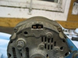 |
The result is – an alternator may have labels on the case, but no actual corresponding terminals. Such is the situation with this particular alternator - the case has labels for an “R” terminal in two different places (one by the #1 terminal and one by the BAT terminal) because R terminals, when present, may be in either of these locations. It also has a label for an F terminal (by the #2 terminal). However, this particular alternator has neither an R nor an F terminal. In fact, R and F terminals are fairly uncommon on these alternators. |
|||||||||||||||||||||||||||||||||||||||||||||||||||||||||||||||||||||||||||||
However, if they were present, the R and F terminals are as follows:
Note: Voltage at the R terminal is pulsating DC and is usually half system voltage. Pulse frequency varies with alternator RPM and alternator model. Normal maximum amp draw for R terminal is 4.0 amps. WiringIt should now be obvious how to wire an SI-series / 2-terminal alternator, but just to summarize: Mandatory connections: 1) Connect the alternator output terminal (B or Bat) to the electrical system's main distribution point (bus bar, junction, etc.) Less optimal alternatives that will work include connecting it to the battery + terminal or a terminal on the starter motor that also connects to the battery + terminal. 2) Connect the #1 voltage regulator terminal (left spade connection) to a source of switched ignition power in one of two ways:
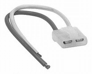
3) Ensure there is a good ground connection between the bare alternator case, the mounting bracketry and the engine block/heads and/or install a dedicated ground wire from the engine block to the alternator's ground terminal (if it has one). Crucial connections: 4) Strictly speaking, the alternator will work with only the three wiring connections listed above, but I consider it crucial for good performance that you also wire up the remote voltage sensing terminal. To do this, connect the #2 voltage regulator terminal (right spade connection) to the vehicle electrical system's main power distribution point (bus bar, main switch, fuse panel, etc.). If the #2 remote voltage sensing terminal is not connected, the voltage regulator will revert to internal sensing of the alternator output terminal voltage - with all the limitations that brings. You will see some alternators wired with a short jumper wire from the #2 terminal directly to the battery connection at the back of the alternator, but this is neither the proper method for remote voltage sensing nor necessary for internal sensing - do it properly or leave it out. Optional connections: 5) If you have an alternator with an R and/or F terminal, and you have a device that can be connected to either one, connect them in the manner specified by the manufacturer of the device. This is a diagram of such an SI-series alternator wired using terminals 1, 2, and B. PlugsBecause these terminals use male spade connectors, in a pinch you can wire to them using standard female spade connectors, but be sure to insulate them well with heat-shrink tubing if you do. The problem with this method, however is that there is no mechanical connection for security and strain-relief. The better and proper way to connect to these terminals is to use a factory connection. These are available and known as a "regulator repair harness". For SI alternators you can use either part number 46-1801 from WAI Global Industries, (www.waiglobal.com) pictured below: or part number C100 from Quick Start Alternators (www.alternatorparts.com), pictured below:
|
||||||||||||||||||||||||||||||||||||||||||||||||||||||||||||||||||||||||||||||
CS Series / 4-terminal AlternatorsThese days, the more common arrangement on CS series alternators is to find four terminals on the voltage regulator, plus the alternator output terminal, and possibly a dedicated grounding terminal (for an actual total of 5 or 6 terminals). These alternators can be wired with anything from 2 to 6 wires, as we shall see (see why I avoid using terms like "2-wire alternator", as it actually tells us almost nothing!) Terminals |
||||||||||||||||||||||||||||||||||||||||||||||||||||||||||||||||||||||||||||||
 |
This is a CS-130 alternator with 4 terminals at the voltage regulator (the black plastic housing labelled "Wiring Terminals" in this pic) plus the alternator output terminal (labelled "BAT" on this model). |
|||||||||||||||||||||||||||||||||||||||||||||||||||||||||||||||||||||||||||||
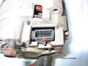 |
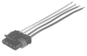
On these later-model alternators, the voltage regulator terminals are pins rather than spade terminals. As such, you can't just use standard electrical connectors - you need the matching plug - see the section on plugs below. |
|||||||||||||||||||||||||||||||||||||||||||||||||||||||||||||||||||||||||||||
 |
On this model, the terminals are labelled P, L, F, and S. Other models will also have four pins in a similar arrangement, but they may be labelled P, L, I, S. |
|||||||||||||||||||||||||||||||||||||||||||||||||||||||||||||||||||||||||||||
The functions of the terminals are as follows:
Notes: -
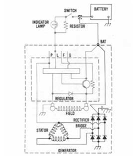
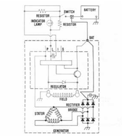
WiringIt should now be obvious how to wire a CS-series / 4-terminal alternator, but just to summarize: PLFS-type Mandatory connections: 1) Connect the alternator output terminal (B or Bat) to the electrical system's main distribution point (bus bar, junction, etc.) Less optimal alternatives that will work include connecting it to the battery + terminal or a terminal on the starter motor that also connects to the battery + terminal. 2) Connect the L terminal to a source of switched ignition power through an indicator lamp wired in series. Also connect a 50 Ohm resistor in parallel with the indicator lamp so that if the bulb burns out, the alternator will still be excited. 3) Ensure there is a good ground connection between the bare alternator case, the mounting bracketry and the engine block/heads and/or install a dedicated ground wire from the engine block to the alternator's ground terminal (if it has one). Crucial connections: 4) Strictly speaking, the alternator will work with only the three wiring connections listed above, but I consider it crucial for good performance that you also wire up the remote voltage sensing terminal. To do this, connect the S terminal to the vehicle electrical system's main power distribution point (bus bar, main switch, fuse panel, etc.). If the S remote voltage sensing terminal is not connected, the voltage regulator will revert to internal sensing of the alternator output terminal voltage - with all the limitations that brings. You will see some alternators wired with a short jumper wire from the S terminal directly to the battery connection at the back of the alternators, but this is neither the proper method for remote voltage sensing nor necessary for internal sensing - do it properly or leave it out. Optional connections: 5) If you have an external device such as a tachometer, hourmeter, or other device, it may be connected to terminal P. Connect the device in the manner specified by the manufacturer of the device. This is a diagram of such a CS-series, PLFS alternator wired using terminals L, S, and BAT. PLIS-type Mandatory connections: 1) Connect the alternator output terminal (B or Bat) to the electrical system's main distribution point (bus bar, junction, etc.) Less optimal alternatives that will work include connecting it to the battery + terminal or a terminal on the starter motor that also connects to the battery + terminal. 2) Connect the L terminal to a source of switched ignition power through an indicator lamp wired in series. Also connect a 50 Ohm resistor in parallel with the indicator lamp so that if the bulb burns out, the alternator will still be excited. 3) Connect the I terminal to a source of switched ignition power through a 50 Ohm resistor wired in series. 3) Ensure there is a good ground connection between the bare alternator case, the mounting bracketry and the engine block/heads and/or install a dedicated ground wire from the engine block to the alternator's ground terminal (if it has one). Crucial connections: 4) Strictly speaking, the alternator will work with only the three wiring connections listed above, but I consider it crucial for good performance that you also wire up the remote voltage sensing terminal. To do this, connect the S terminal to the vehicle electrical system's main power distribution point (bus bar, main switch, fuse panel, etc.). If the S remote voltage sensing terminal is not connected, the voltage regulator will revert to internal sensing of the alternator output terminal voltage - with all the limitations that brings. You will see some alternators wired with a short jumper wire from the S terminal directly to the battery connection at the back of the alternators, but this is neither the proper method for remote voltage sensing nor necessary for internal sensing - do it properly or leave it out. Optional connections: 5) If you have an external device such as a tachometer, hourmeter, or other device, it may be connected to terminal P. Connect the device in the manner specified by the manufacturer of the device. This is a diagram of such a CS-series, PLIS alternator wired using terminals L, S, I, and BAT. PlugsTo plug the wires into a CS-series alternator you need the factory-style plug. If you can scavenge one from a donor vehicle, great. If not, they are available separately from a number of sources, such as: For CS-121, CS-130, and CS-144 alternators you can use either part number 46-1803 from WAI Global Industries, (www.waiglobal.com) pictured below: or part number C120 from Quick Start Alternators (www.alternatorparts.com), pictured below: For CS-130D alternators you can use either part number 46-1810 from WAI Global Industries, (www.waiglobal.com) pictured below: or part number C130D from Quick Start Alternators (www.alternatorparts.com), pictured below: PerformanceIf you're with me so far, you pretty much know all you need to know in order to shop for your next replacement, factory upgrade, or custom-built, high-output alternator. Obviously, there are way too many variables for me to be able to tell you exactly what part number you need - but there are a few points on alternator performance I can summarize which will be helpful for you to keep in mind when shopping; as well as a few ideas on how to go about finding that perfect alternator for your needs. The principle factors governing alternator performance include:
Max SpeedThe faster the alternator spins, the more power it will make. Therefore, one way a manufacturer can make an alternator produce more power is to build it in such a way that it is capable of being spun faster. Methods to do this may include stronger rotating parts like the rotor and larger / better bearings. Most alternators are advertised or sold with a performance rating that is actually the maximum possible output which of course occurs at the maximum permissible RPM. For this reason, not all identically rated alternators are equal. In fact, in order to properly compare alternators, you really need the alternator's performance curve which is a graph of the alternator's output vs. its rpm. Such a curve would look something like this: For must users, the shape of the curve is just as important as its peak value. The curve pictured above is actually a very good one - it shows the alternator putting out 40 amps at idle, rising quickly to almost 140 amps at 3000 alternator RPM (about 1000 engine RPM), then levelling off. It shows us that this alternator makes good idle power, quickly comes up to near-max output, and doesn't need to be driven ludicrously fast to produce near-maximum output. Tip: When shopping for a performance alternator, always ask to see the performance curve. Be wary if the company will not or cannot produce it for you. Idle PerformanceFor most of us, idle performance is more important than max output rating. That's because, just like the engine's performance, we don't spend a lot of time at max rpm. A useful, driveable engine require low rpm torque as much as max rpm horsepower. Similarly, the most useful alternator is one that produces good output down low - not only because we spend more time at lower rpm, but also because it's often when we're at or near idle that we consume the most electrical power - with the air con on, the stereo pumping, and the electric fans on full to keep the engine cool. You will rarely, if ever, see idle performance listed in an alternator's description - the adds always say things like "150 amp alternator". This is another reason that the performance curve is so important. Without it, you may buy an alternator that puts out 150 amps at 8000 rpm, but that drops like a stone below that - and it would be all but useless. The WindingsWhen high-output alternators are built, it is chiefly the windings that are most upgraded over stock units of the same size. And most important of those is the stator windings. The quality of the copper, the method by which it is wound, and the sheer volume of the windings all play a role. And since copper is expensive, and winding alternators time consuming, the old adage applies - you get what you pay for. Of course, another thing to be wary off is extremely high-output rated alternators in small cases. How could they fit the required windings in there? Tip: I would be wary of alternators advertised as having 100% or more output than the stock units whose case they are using. In other words, a 105 amp 10-SI, a 150 amp 12-SI, and a 250 amp CS-144 are all reasonable. But a 200 amp 10-SI is not! Regulator / RectifierJust as when building a HO engine you also need to upgrade cooling, fuel delivery, and ignition systems for long-lasting reliable performance, so also must you upgrade alternator components other than just stuffing the world's supply of copper windings in the case. Chief candidates include the voltage regulator and rectifier. Rectifiers especially, being that they are "valves", are subject to wear and failure if not properly rated for the pressure (voltage) and flow (current) they will be subject too. Just as using a $2 plumbing valve in a high-pressure fueling system isn't smart, so using stock components in a beefed-up alternator invites failure. Tip: Ask the manufacturer what and how they upgrade internal components other than the windings in their HO models. Heat and CoolingOnce agin, just like a motor - the more power you make the more heat is created when doing so. Failure to deal with this extra heat leads to malfunction, failure, and an early death (along with a waste of money). This is an area where unscrupulous companies can take shortcuts and save a few bucks - but it's a disaster waiting to happen. The good companies will be pleased to explain to you what cooling modifications and upgrades they make to deal with the extra heat of producing 150, 200, or more amps. And it's a LOT of heat. Recall that the formula for Watts (a measure of heat) is current squared times resistance. Therefore if you produce more current (remember it is SQUARED!) you end up producing a lot more heat - way more heat. For example, let's say we take a 100 amp alternator and rebuild it to produce 150 amps - how much more heat would it make? For the 100 amp alternator, let's assume 0.05 Ohm resistance in the stator windings, and a 15% loss as heat. Watts = A^2 * Ohms. Therefore Watts = ((100*100)*15%) * 0.05 = 75 Watts of heat. Now, let's use the same figures, but with an output of 200 amps. Watts = A^2 * Ohms. Watts = ((200*200)*15%) * 0.05 = 300 Watts of heat! How much heat is 300 watts? A lot! For example, many small electric aux. heaters for cars are in the 150-300 watt range! So - we increased our electrical output by half (50%), BUT that resulted in a heat production increase of three times or 300%! Clearly - cooling and heat-handling capacity are crucial components of a good alternator upgrade. Cooling upgrades to look for include things like:
Also, keep in mind that the fan on the front of an alternator is a "puller" fan (for the same reason puller fans are preferred on radiators - they're more efficient and move more air than pushers). This means it draws air through the vents in the back of the alternator, pulls it through the alternator internals, and exhausts the hot air out the front. This means, of course, that where you mount your new HO alternator is also very important. You don't want the air intakes on the back to be right beside a hot exhaust manifold, for example. You also need to make sure that the air vents remain clear and unrestricted - especially after off-road use. Pulley SizeWe have already discussed the performance curve and how alternator output relates to rpm. It is very important to understand that this rpm is ALTERNATOR rpm and not engine rpm. Typically (almost always, in fact) alternators are driven by pulleys that are smaller than the crank pulley driving them. This produces an overdrive situation where the alternator is driven faster than the engine that is driving it - much the same as an overdrive gear in a transmission or even on a bicycle. The amount by which the difference in pulley sizes overdrives the alternator is known as the "pulley ratio" and is calculated the same way a gear ratio is. It is the ratio of the drive (crank) to driven (alternator) pulley sizes. The formula is: crank pulley diameter / alternator pulley diameter = ratio. Common alternator drive ratios are in the 3.0 range - meaning the alternator pulley is 1/3 the size of the crank pulley and therefore the alternator is driven at 3 times the engine speed. So, if we use a smaller pulley, we get greater alternator output per engine rpm. This is most noticeable at low engine rpm because alternator output tends to level off at alternator shaft rpm's above 3000 or so (depending on the unit, and in accordance with the performance curve). However, there is always a price to pay, and in this case we have to be careful not to use such a small pulley that at high engine rpm we exceed the alternator's maximum rpm. For example, it's no use installing a 3x overdrive pulley on an alternator installed in a race car that runs all day at 7000 engine rpm - because the alternator will be spinning at 3 x 7000 = 21,000 rpm! Fortunately, race car's spend little time at idle and even when they do their electrical demands are low (no a/c, stereo, electric windows, etc.) so they can operate with high-ratio (low numerical) alternator pulleys. If you're starting from scratch with determining pulley size, proceed as follows:
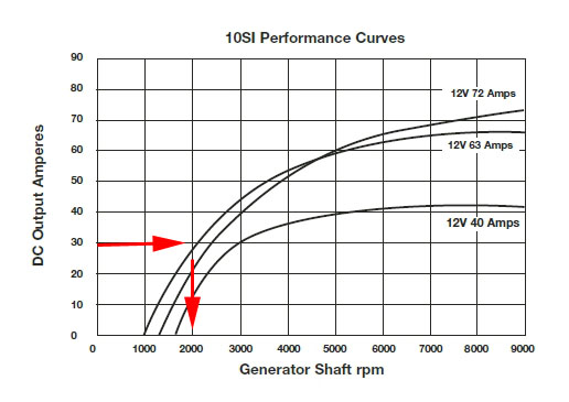
To check for alternator over-speed:
To determine alternator output at engine idle:
To determine maximum alternator output (max charge rate):
Of course, selecting or changing the pulley size is an exercise in compromise. Because your engine will likely run slowly at times, and rev very high at other times, there is no “perfect” pulley drive ratio for all applications. Improving Output at Idle SpeedIn most cases, an alternator's weakest performance is at idle. In fact, normal alternator output at idle is commonly only 40-50% of rated alternator output. Even without changing the alternator, idle performance can normally be improved by selecting a different (smaller) pulley that multiplies engine RPM by a greater factor, thus increasing the alternator shaft rpm and therefore alternator output. Of course, you must make sure you don't overspeed the alternator at high rpm, as described above. Probably the best way to improve idle performance is by upgrading the alternator, even if you don't need a higher maximum output. Newer design and larger alternators will have better performance curves, cool better, and are able to produce a larger percentage of their rated output over a wider range of RPM and for longer periods of time without suffering damage. Once again - your best friend is the performance curve for determining what is right for your needs. Failure ModesSo what can go wrong with an alternator? Fortunately, not very much, as they are pretty simple and rugged devices. However, they do operate in a pretty harsh environment, are subject to a lot of heat, and don't last forever. This is a list of some of the most common things that can go wrong. 1) Wiring Often a problem that seems like it might be the alternator isn't the alternator at all. Fortunately, there aren't a whole lot of wires to go wrong, but they should always be your first check. Make sure all connections are clean and tight; make sure that there are no short circuits or open circuits in the wiring (never run an alternator with the output terminal in an open-circuit condition, by the way); and make sure the wires are not crimped, pinched, frayed, tight, or otherwise in distress. Also make sure the connections between the alternator case, mounting brackets, and engine block/head are clean, corrosion free, and tight. Don't forget to check fuses, circuit breakers, and fuseable links! 2) Belt Another major culprit is also not the alternator, but the drive belt. Make sure it is clean, not worn or frayed, free from glaze, appropriately tensioned and not slipping, jumping, or jamming, particularly at high engine rpm. Check to make sure there is sufficient engagement between the belt and pulleys and modify belt routing / pulley arrangement as required. 3) Bearings As we know, the rotor spins at very high rpm within the case, and is supported by at least two bearings - normally sealed needle bearings. Heat, time, and harsh conditions such as mud, water, and dust will eventually bring the bearings to the end of their useful service life. This will most often show up as a grinding or squealing noise. To make sure that the noise is in fact the alternator bearings (and not some other bearing like an idler pulley), disconnect the alternator drive belt and turn the alternator pulley by hand listening for any noise and feeling for any roughness or harshness. Also check for endplay and sideplay in the pulley. Be aware that it is also possible for the bearings to seem OK by hand, but to be noisy when subjected to the load of the drive belt, so watch out for that. Fortunately most alternator bearings are available separately or in rebuild kits and they are fairly easy to R&R. 4) Windings. The windings take a real electro-magnetic beating. Over time they can break down, short out, or open-circuit. The stator windings are most often the culprit with bad windings. Because each of the three phases in the stator has its own separate windings it is possible for the alternator to still operate, albeit at much reduced output, with one or even two sets of bad windings. This may be the case if it operates but output is low. Of course, if the rotor windings are bad, the alternator will not operate. 5) The Electrical Bits Inside The other internal parts are also subject to wear, thermal breakdown, and have a finite life. Chief culprits include the brushes, the voltage regulator, and especially the rectifier. Over time and with use, the diodes in the rectifier weaken and don't work as efficiently as they used to - especially when hot. Eventually they can stop working altogether. One possible tell-tale sign of a rectifier on the way out is an alternator that works well when cold, but whose output weakens as it gets hotter and/or electrical demands increase. TroubleshootingSadly, these days we live in a discard-and-replace world. Nobody fixes anything anymore. Cheap offshore manufacturing has just made it cheaper and much more convenient to junk a suspected bad part and replace it. To be honest - this isn't always a bad thing - the availability and reasonable price of remanufactures alternators make this a pretty valid option - IF you are sure the alternator is bad. The possible exception may be the SI-series alternators that are very rebuild friendly. Of course, we should probably still be able to do a little troubleshooting, as often times an electrical or charging system problems shows up and we are not sure whether it is the battery, alternator, starter motor, solenoids, wiring, relays, fuses, etc. etc. Following is one approach to help narrow down whether the alternator is bad: Eliminate the simple/obvious/unrelated
Check Alternator Warning Lamp Operation
Perform Voltage ChecksWith engine running and all electrical accessories on, rev to 1500 engine rpm and measure voltage at alternator, main electrical junction, and battery. They should all be 13.8 – 14.5V.
With engine running check voltage at battery - should be 13.8 – 14.5V (anything above 15.5V means battery is over-charging (dangerously!). Anything below 12.7V means the battery is not charging.
Check field current. With ignition on / engine off, check with a voltmeter for ~12 volts at the field (exciter) wire at the alternator. (terminal 1, L, and/or I).
Eliminate the voltage regulator as the problem by bypassing it. If your alternator has a "full field" capability you can use it to bypass the voltage regulator and supply full field voltage to the rotor. There are various ways of doing this depending on the alternator. SI=series alternators have a regulator by-pass test hole in the back, on Mopar alternators you typically jumper the field terminal (look for the green wire) to ground, on Ford alternators you normally connect the BAT and FLD terminals. In the case of an SI-series alternator, insert a screwdriver into the test hole until it touches the metal tab, then touch the side of the screwdriver to the case, grounding the tab. If when you "full-field" the alternator output improves to "full voltage" (13.8 – 14.5 VDC is now read at the BATT terminal) the voltage regulator is faulty. If not, the alternator (windings / rectifier, etc.) are faulty. Additional Checks for CS-series, 4-terminal AlternatorsWith ignition switch on and engine stopped, lamp should be on. If not, detach harness at alternator, use fused jumper to ground "L" terminal lead on harness. Be very carefully to properly identify "L" terminal lead. Grounding "L" terminal should cause indicator lamp to light. If lamp does not light, locate open circuit between grounding lead and ignition switch. Bulb may be bad. With ignition switch on, engine running at moderate speed, lamp should be off. If not, stop engine, turn ignition switch back on, and detach wiring harness at alternator:
With engine running check voltage at battery - should be 13.8 – 14.5 volts (anything above 15.5VDC means battery is over-charging (dangerously!). Anything below 12.7VDC means the battery is not charging.
Additional DataThe following links, documents, spec sheets, and catalogues provide an additional wealth of information about alternators. They can be very useful when trying to identify an alternator, choose an upgrade or replacement, identify specific specifications, learn more about disassembling and repairing alternators, etc. They are provided here for your information, learning, and convenience. VERY IMPORTANT - do not call up a manufacturer and quote prices you found here - by the time you are reading this it is highly likely that the catalogues are out of date. If you do, it ticks of the companies and they write me angry letters demanding I remove the offending documents and then you loose your convenient central data source. This is no joking matter - people do it and I do get angry letters - which ticks me off too. If you need current information - like pricing - just go to the manufacturer's website and find the latest catalogues or online data. PDF Documents:Exploded Diagrams of Delco-Remy Model Alternators:Other Data:Bosch Charging Systems Datasheet Delco-Remy Alternator Identification Guide Delco_Remy CS-144 Reassembly Instructions Delco-Remy Diagnostic Procedures Manual Delco-Remy Electrical Specifications & Selection Guide - Starters and Alternators Delco-Remy Quick Reference and Cross Reference Guide - Starters & Alternators Delco-Remy 10SI, 12SI & 15SI ALTERNATOR INSTALLATION INSTRUCTIONS Powermaster INSTRUCTION SHEET - GM CS Series Performance Alternators Powermaster Alternator Application Guide Powermaster INSTALLATION INSTRUCTIONS - Alternators Links:http://parts-catalog.acdelco.com/catalog/catalog_search.php http://www.delcoremy.com/Alternator/Literature.aspx http://www.madelectrical.com/electrical-tech.shtml http://www.alternatorparts.com/ http://www.alternatorparts.com/repair_manuals/10si-15si-type-116-136-repair-manual-contents.html http://www.alternatorparts.com/CS144_alternator_repair_video.htm http://www.powermastermotorsports.com/ http://www.autoshop101.com/trainmodules/alternator/alt101.html http://www.waiglobal.com/alternator_parts.html |
||||||||||||||||||||||||||||||||||||||||||||||||||||||||||||||||||||||||||||||
 |
 |
|
