 |
14-Bolt Disc Brakes V2 By Bill "BillaVista" Ansell |
IntroductionSeveral years ago I wrote an article about how I converted my 14-Bolt full-float rear axle to disc brakes. They worked OK, and obviously lasted quite a while - but that project had a couple of major flaws that recently began to manifest themselves as annoying problems - especially since the addition to the buggy of hydroboost brakes, a more powerful engine and my new love of driving fast. So I set about to re-do them and correct the problems. Here's a look: |
 |
The ProblemFor some time I had been breaking slide pins and breaking the ears off the calipers. I tried to just ignore the underlying problem and replace parts as they broke, but in my heart I knew something wasn't right and my lazy approach wasn't going to cut it forever and I would have to do something about it. |
|
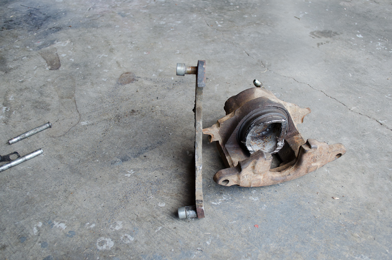 |
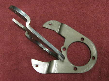
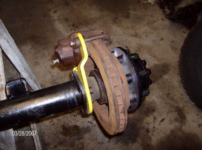
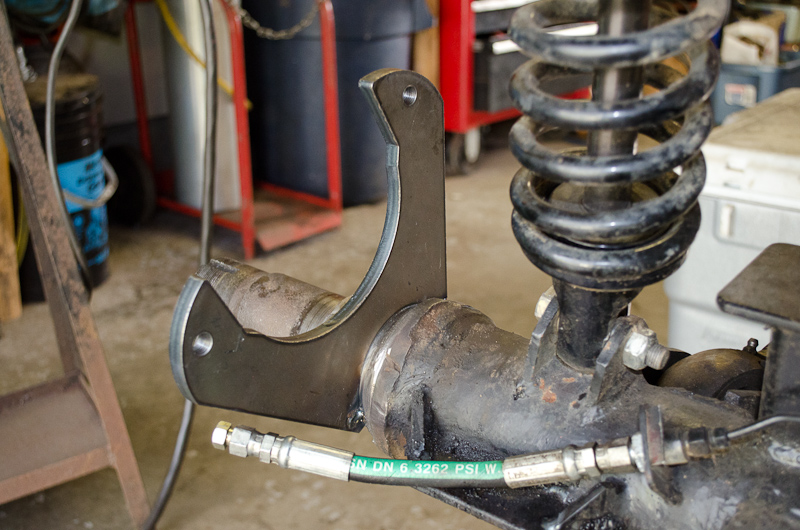
It turns out that before long, after one particularly great day of hard wheeling, the whole braking system on the left rear just came apart. What had happened was this: When I made my first set of brackets, I did not get the layout and drilling / tapping of the calliper mounting holes precise enough. That means, every time I applied the brakes, the caliper was trying to twist on the pins (hence the breaking pins and broken ears on the callipers). What I didn't know was, it was also twisting the bracket, bit by bit, making things worse and snowballing the problem. Eventually it all grenaded. You can see the bent bracket and the busted pins in the pic at left. |
|||||||||||||||||||||||||||||||||||||||||||||
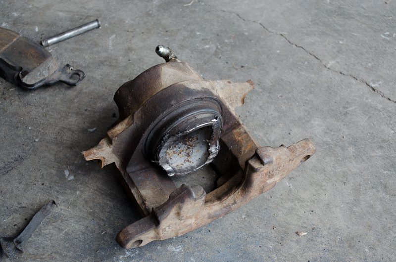 |
And when the pins broke and the calliper got loose the inside pad fell out so the piston itself spent half the day bearing on the rotor... | |||||||||||||||||||||||||||||||||||||||||||||
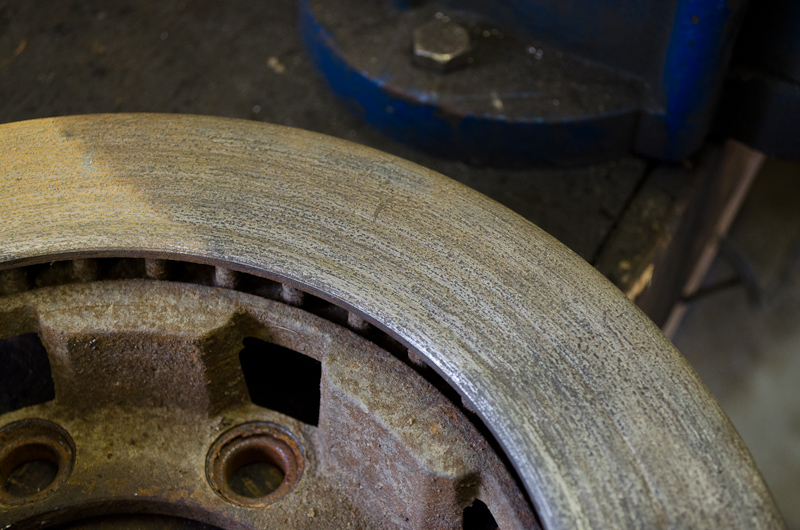 |
...and the rotor didn't like that none too much either! | |||||||||||||||||||||||||||||||||||||||||||||
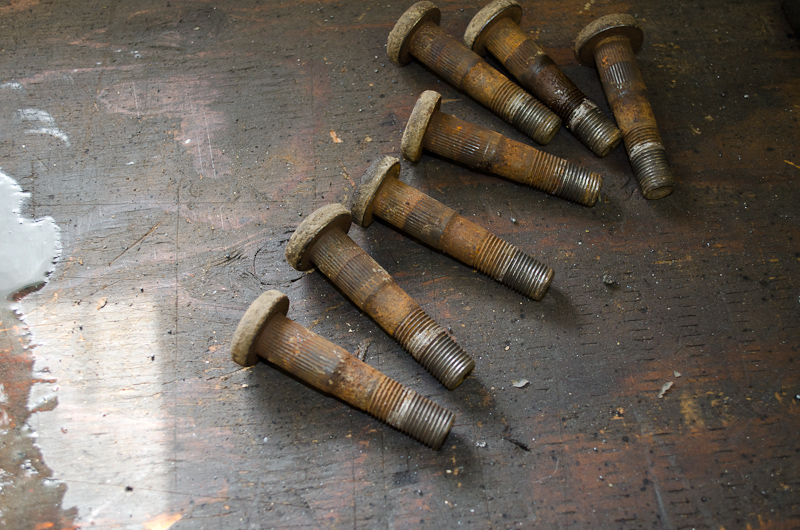 |
Finally, the other problem I had been living with but was eager to cure now that I'd been forced into corrective action, was replacing the old stock 14-Bolt SRW wheel studs (Dorman p/n: ). | |||||||||||||||||||||||||||||||||||||||||||||
 |
Because reusing the old stockers results in not enough thread engagement with the wheel nuts. | |||||||||||||||||||||||||||||||||||||||||||||
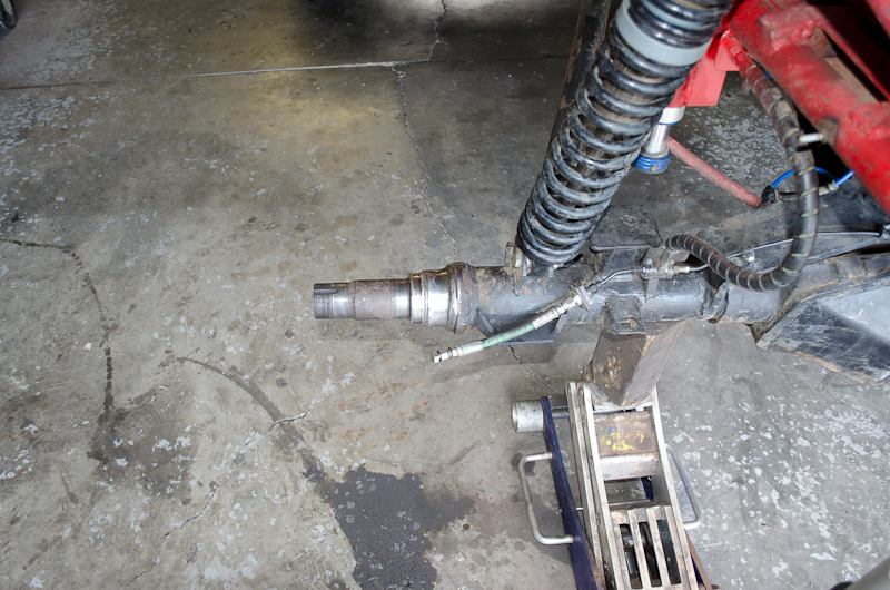 |
First things first - you need to remove the wheel and tire and strip the axle down to the bare spindle. If you need help with this, see the original article. | |||||||||||||||||||||||||||||||||||||||||||||
 |
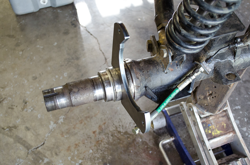
Spindle: A - Outer wheel bearing seat. |
|||||||||||||||||||||||||||||||||||||||||||||
We should note a couple of important points at this stage. First - if you look closely you will notice that the spindle area where weld-on disc brake bracket will be installed (labelled "D" in the above pic) is not perfectly round, but actually very slightly tapered being larger in diameter on the outside and slightly decreasing towards the outside (end) of the spindle. So what? Well, this is going to add to the challenge of getting the bracket perfectly square to the axle. And we know the bracket must be square (as well as the holes perfectly spaced and true) otherwise every press of the brakes twists and bends stuff until something (or everything!) goes BOOM! Now, to be fair, even a 3/8" thick bracket doesn't really have enough surface area on the inner radius to be relied upon for proper indexing square to the axle, but the fact that the spindle area is neither perfectly cylindrical nor exactly 3.25" in diameter adds to the challenge of getting the bracket square and true which, trust me, is very important. We'll return to this topic and how to deal with it momentarily, but for now, let's take a look at another option should you not want to mess with tricky alignment or even weld. Bolt-on BracketsIf your 14-Bolt still has the original stock drum-brake backing plate brackets, there are options for bolt-on brackets. These have not-only the advantage that you don't have to grind and weld to install disc brakes, but also they automatically position the bracket, and therefore the caliper in the correct position (both height over the rotor and spacing laterally on the axle). |
||||||||||||||||||||||||||||||||||||||||||||||
 |
These are bolt-on brackets from Ruffstuff Specialties designed for the '73-'87 single rear wheel 14-Bolt axle housings - part number: 14BSRW. Note the bend / offset in the bracket to provide the proper lateral spacing from the stock drum-brake backing plate bracket. *Note that all the options in this article use the same calliper and rotor, which we'll get to shortly. Photo courtesy of and copyright Ruffstuff Specialties , all rights reserved. Used with permission. |
|||||||||||||||||||||||||||||||||||||||||||||
 |
Here's a picture of the above bolt-on bracket installed with calliper and rotor mounted. Here you can see clearly how the offset in the bracket is necessary to position the calliper laterally. Photo courtesy of and copyright Ruffstuff Specialties , all rights reserved. Used with permission. |
|||||||||||||||||||||||||||||||||||||||||||||
 |
These brackets, also from Ruffstuff, part number: 14BCNC, are designed for the Cab & Chassis 14-Bolt (C&C) axle, '73-'87. Note the even deeper offset required. If you're unfamiliar with the different types of 14-Bolt axles and the terminology, see my 14-Bolt Bible article. Photo courtesy of and copyright Ruffstuff Specialties , all rights reserved. Used with permission. |
|||||||||||||||||||||||||||||||||||||||||||||
 |
Finally, these brackets from Ruffstuff, part number: 14CCSRW, are designed for those running C&C or dual-rear-wheel (DRW) hubs (Type B hubs) on a '73-87 single-rear-wheel (SRW) axle housing. Photo courtesy of and copyright Ruffstuff Specialties , all rights reserved. Used with permission. |
|||||||||||||||||||||||||||||||||||||||||||||
Weld-on BracketsIf you don't have an axle for which there is a bolt-on bracket available, or if you want the lightest or cleanest installation, or like me, you no longer have stock flanges to bolt to, then you need to use a weld-on bracket. |
||||||||||||||||||||||||||||||||||||||||||||||
 |
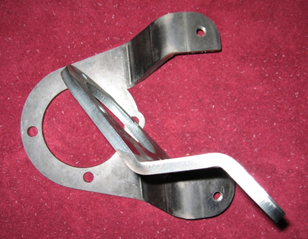
I used the weld-on brackets from Ruffstuff, part number: WELD325, which are listed as "Weld On Disk Brake Bracket 3.25" Axle" |
|||||||||||||||||||||||||||||||||||||||||||||
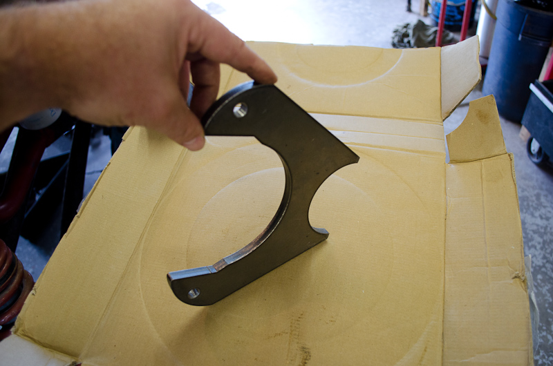 |
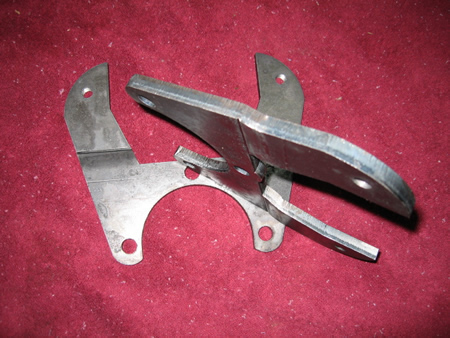
I browsed quite a few brackets online before I bought these. First - things sure have come a long way in the last 10 years. It wasn't so long ago that there were few choices and most of our custom stuff we had to make ourselves (which sucked for unskilled hacks like me!) Anyway, I liked these because they seemed to have plenty of meat on them, are made of 3/8" Plate and are cut for a 3.25" tube which is close to the OD of the spindle where they need to be welded. And of course they are drilled, tapped, and spaced to use the '77 Chevy 3/4 ton rotor (12.5" diameter rotor) and calliper. |
|||||||||||||||||||||||||||||||||||||||||||||
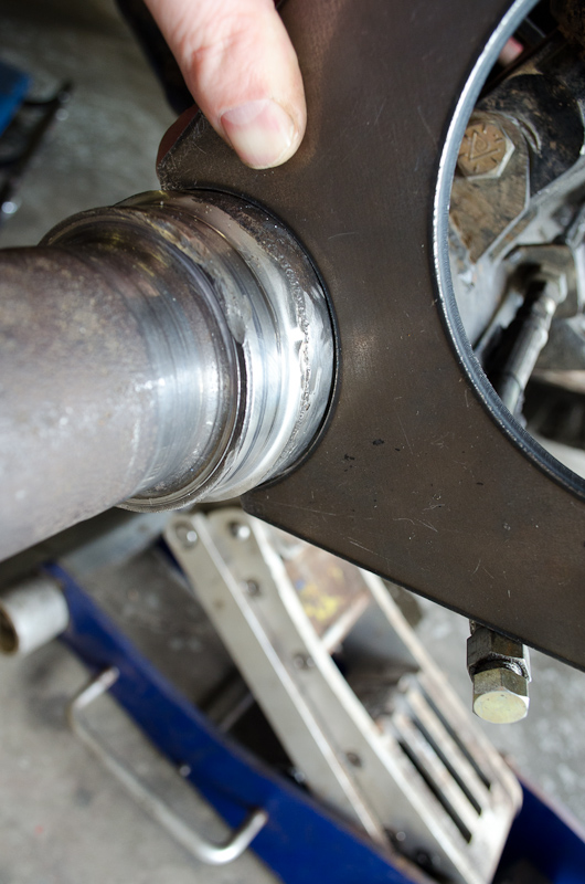 |
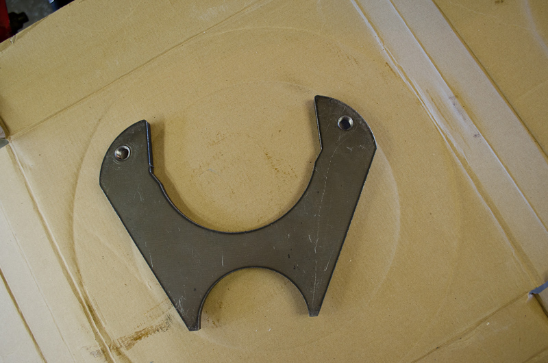
Now, the 14-Bolt axle is not a 3.25" diameter axle, but as we know, the bracket isn't going to be welded on the axle tube, but rather on the spindle. In fact, the area on the 14-Bolt spindle is slightly smaller in diameter that 3.25", but nonetheless the brackets fit pretty well and we're going to need to do some work to make sure everything is properly aligned before we tack then weld it anyway. Before we get to that, let's have a look at some of the other parts involved. |
|||||||||||||||||||||||||||||||||||||||||||||
Hubs |
||||||||||||||||||||||||||||||||||||||||||||||
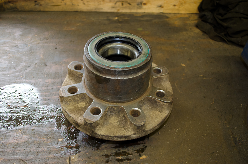 |
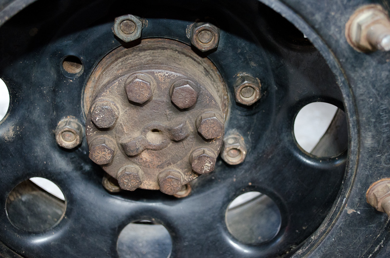
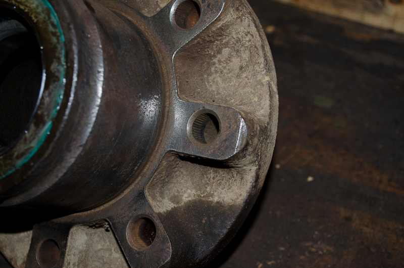
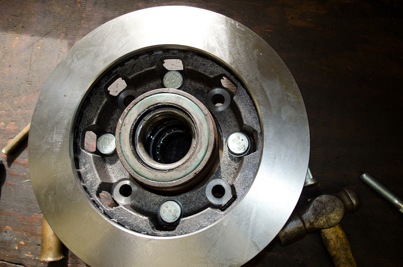
This is the back side (the inside) of a SRW 14-Bolt hub with the old brake drum removed. The disc brake rotor will be staked on the backside of the hub, on the face shown at left - the same place the drum was staked. |
|||||||||||||||||||||||||||||||||||||||||||||
 |
This is the front or outside of the hub, showing the wheel mounting surface. | |||||||||||||||||||||||||||||||||||||||||||||
 |
Side view of the hub. | |||||||||||||||||||||||||||||||||||||||||||||
 |
The thickness of the wheel-mounting flange is 1.440". This is important because it relates to the length of the wheel studs required, as they must be long enough to go through the rotor, through this flange, through the wheel's mounting flange, and have enough length remaining to fully engage the lug nuts. | |||||||||||||||||||||||||||||||||||||||||||||
 |
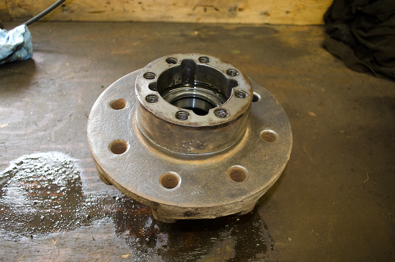
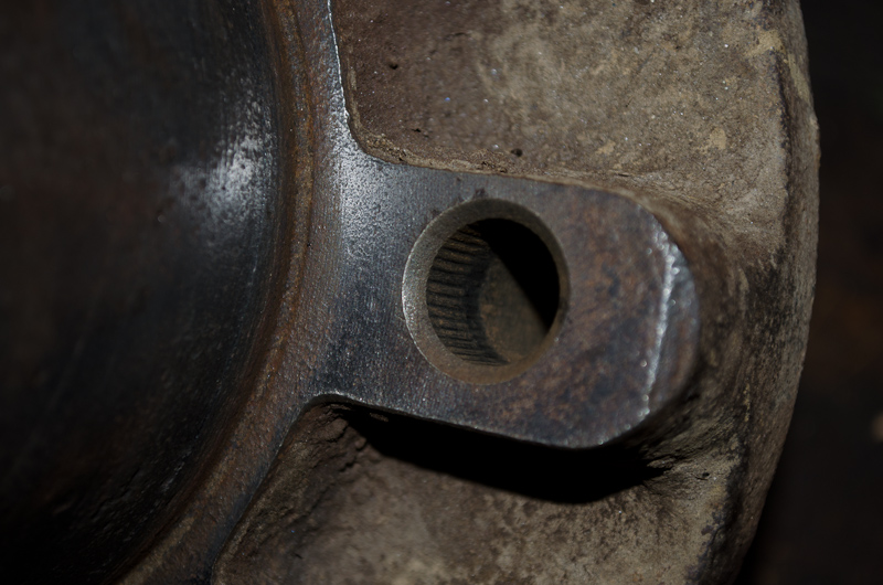
The wheel-stud holes in the hub have a chamfer on the back side, and the top part of the hole is internally splined or knurled for engaging the wheel studs securely. | |||||||||||||||||||||||||||||||||||||||||||||
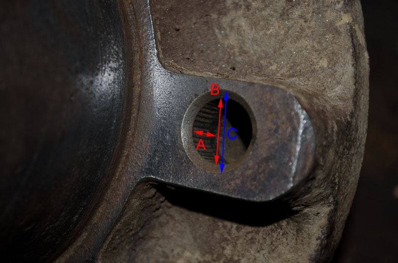 |
Rough dimensions are: A: Depth of the internal knurl - approx. 1/2" B: ID of the hole (groove-groove in the knurl) - approx. 0.608" C: Diameter of the chamfer - approx. 0.734" |
|||||||||||||||||||||||||||||||||||||||||||||
Callipers, Pads, and RotorsMost places, you will read that the callipers, pads, and rotor required can be sourced from 1972-1986 Chevy 3/4-ton trucks (rotors, pads, callipers) and 1972-1986 Chevy 1/2-ton trucks (pads & callipers). While that is a true statement, there's actually a bit more to it than that, including a larger HD calliper option, a difference between metric and standard brake line fittings, and a huge list of potential application. Here are the details, BillaVista style: CallipersThere are actually three different callipers to choose from: 1) Standard front calliper, 2-15/16" Piston, standard 7/16"-NF brake line (banjo bolt) fitting [1971-1978]. 2) Standard front calliper, 2-15/16" Piston, metric 10mm x 1.0 brake line (banjo bolt) fitting [1979-1986, 7,200 Lbs GVW, RPO JB6/JD6]. 3) Heavy-Duty front calliper, 3-5/32" Piston, metric 10mm x 1.0 brake line (banjo bolt) fitting [1971-1986, 8,400 Lbs GVW, RPO JB7/JD7] What's this RPO thing? RPO CodesGM uses a 3-digit code, called an RPO (an acronym for Regular Production Option), to identify the options with which a specific vehicle is built. They are listed on a label or sticker called the Service Parts Identification (SPID) label. On late-model GM trucks this label is found inside the glove box, on earlier trucks it may be on a door jamb or kick panel. Some of the most famous RPOs are Z28 (performance package found on Camaros) and LS1 (specific type of V8 engine). By looking up RPOs in a reference table you can identify the options with which the vehicle was built. Note that sometimes they are referred to as "options codes", "equipment codes", or even specific names such as, in this case, "brake codes". |
||||||||||||||||||||||||||||||||||||||||||||||
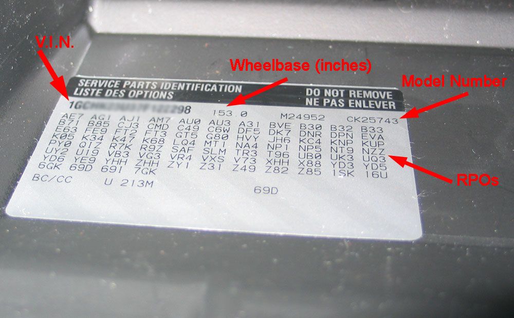 |
Just to illustrate what I'm talking about, this is the Service Parts Identification (SPID) label found in my 2007 Chevy truck. It includes other information along with the list of RPOs, including the V.I.N., wheelbase, paint codes, and vehicle model number. | |||||||||||||||||||||||||||||||||||||||||||||
Now, back to brakes - you will note that, in the description above I mentioned RPOs (aka brake codes) such as JB6 and JB7. If you search through this master list of GM RPOs, you will find the following definitions for these brake-related RPOs: JB5: Brake, Power, Disc/Drum, 6,400 Lbs GVW JD5: Brake, Dual Power, Disc/Drum, 6,400 Lbs GVW (Dual Diaphragm Vacuum Booster) Some parts places and / or manufacturers refer to these RPOs or "brake codes" when you order or lookup parts, so now you know what they are referring too. So, in summary, you can choose to use a standard calliper with a 2-15/16" piston and either standard or metric brake line fitting. Or you can choose a more heavy duty calliper with a larger 3-5/32" piston and a metric brake line fitting (there is no HD calliper with standard brake line fitting). They all fit over the same rotor, take the same pads, and bolt up to the same brackets. |
||||||||||||||||||||||||||||||||||||||||||||||
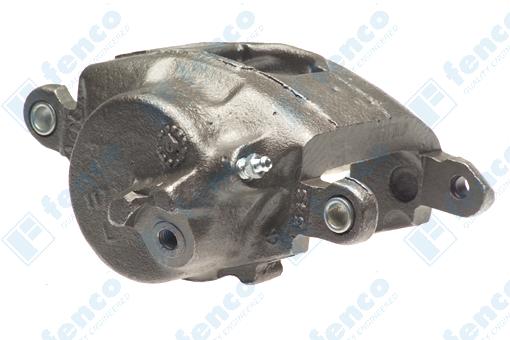 |
The standard callipers (metric and standard) are indistinguishable from one another visually, and both look like this... | |||||||||||||||||||||||||||||||||||||||||||||
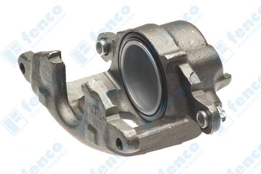 |
...and this. | |||||||||||||||||||||||||||||||||||||||||||||
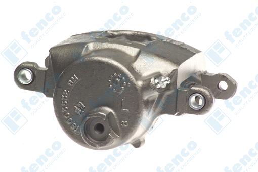 |
The HD callipers also look very similar, but there are differences. The most easily distinguished feature is the area where the brake line attaches and the raised ring around it. |
|||||||||||||||||||||||||||||||||||||||||||||
 |
The other side of the HD calliper. | |||||||||||||||||||||||||||||||||||||||||||||
Here are some part numbers for the different callipers: Standard calliper, 2-15/16" Piston, 7/16"-NF brake line (banjo bolt) fitting.Fenco Callipers: Front Left: p/n: C502 / Front Right: p/n: C503: 1971-1978 Chevy K20 4x4 3/4-ton pickup. Wagner Callipers: Front Left: p/n: CR76050 / Front Right: p/n: CR76051: 1971-1978 Chevy K20 4x4 3/4-ton pickup. Standard front calliper, 2-15/16" Piston, 10mm x 1.0 brake line (banjo bolt) fitting.Fenco Callipers: Front Left: p/n: C528 / Front Right: p/n: C529: 1979-1986 Chevy K20 4x4 3/4-ton pickup 7,200 Lbs GVW, RPO JB6/JD6. Wagner Callipers: Front Left: p/n: CR130212 / Front Right: p/n: CR130213: 1979-1980 Chevy K20 4x4 3/4-ton pickup, 7,200 Lbs GVW, RPO JB6. Front Left: p/n: CR98886 / Front Right: p/n: CR98887: 1981-1986 Chevy K20 4x4 3/4-ton pickup, 7,200 Lbs GVW, RPO JB6. Heavy-Duty front calliper, 3-5/32" Piston, 10mm x 1.0 brake line (banjo bolt) fitting.Fenco Callipers: Front Left: p/n: C530 / Front Right: p/n: C531: 1979-1986 Chevy K20 4x4 3/4-ton pickup 8,400 Lbs GVW, RPO JB7/JD7. Wagner Callipers: Front Left: p/n: CR98954 / Front Right: p/n: CR98955: 1979-1986 Chevy K20 4x4 3/4-ton pickup 8,400 Lbs GVW, RPO JB7. *Note that all these part numbers are for bare or "unloaded" callipers - meaning all you get is the bare calliper - no pins, no clips, no pads. Most manufacturers also sell callipers that are "semi-loaded" (meaning they include the hardware such as pins and clips) or "loaded" (meaning they include the hardware and pads. Often the part numbers are similar, but with a different refix. For example, "C528" is a standard metric-fitting calliper from Fenco, and "SLC528" is the same thing but Semi Loaded (SL). "CR98954" is an unloaded Wagner HD calliper, "L98954" is the same calliper loaded. But there are no hard and fast rules to this naming system. |
||||||||||||||||||||||||||||||||||||||||||||||
 |
This is some of the hardware that *usually* comes with these calipers in "semi-loaded" configuration. I say *usually* because, again, variations are possible. Pic shows enough for two callipers. Clockwise from top we have: - The abutment clips (one per caliper, clips on the inboard pad and holds it in place on the piston during installation). - Copper sealing washers for the brake line attachment - The little silver bushings that go in the ears of the calliper, through which the mounting bolts / slide pins go. |
|||||||||||||||||||||||||||||||||||||||||||||
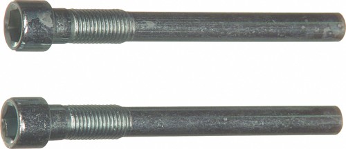 |
Semi-loaded callipers normally also include a pair of mounting bolts / slide pins per calliper too. | |||||||||||||||||||||||||||||||||||||||||||||
Here are some screen caps from the Federal-Mogul / Wagner online parts-finder app showing calliper applications: Standard calliper, 2-15/16" Piston, 7/16"-NF brake line (banjo bolt) fitting.Part numbers: CR76050 / CR76051
Standard front calliper, 2-15/16" Piston, 10mm x 1.0 brake line (banjo bolt) fitting.Part numbers: CR130212 /CR130213
Part numbers: CR98886 / CR98887
Heavy-Duty front calliper, 3-5/32" Piston, 10mm x 1.0 brake line (banjo bolt) fitting.Part numbers: CR98954 / CR98955
Two final points about ordering parts to keep in mind: 1) It is best to never quote an application on or very near a transition year, if you can help it. Sometimes funny things happen with production runs close to transition years. For example, the standard calliper with standard threads fits 1971-1978 Chevy K20, but I would never quote 1971 or 1978 to a counterman or online ordering system - too much risk. Pick a year in the middle. 2) I do my best to be accurate and complete, but even I can make mistake. Also, companies get bought, sold, re-structured, and change their inventory, part numbering, and other practices. Therefore it's always a good idea to cross check a part number or application before spending money. Fortunately there are lots of good sites with lost of good online data available where you can do your own confirming; such as those at the following links: |
||||||||||||||||||||||||||||||||||||||||||||||
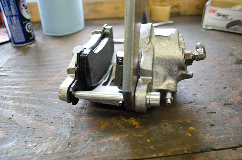
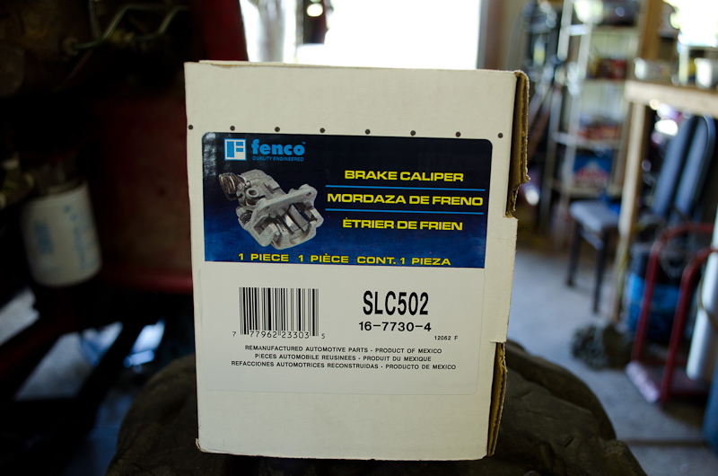 |
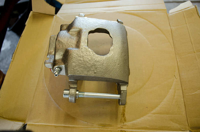
This is one of my callipers. the left one. It's a semi-loaded caliper by Fenco, the standard one with the 2-15/16" piston, and 7/16"-NF brake line (banjo bolt) fitting. p/n: is SLC502, the right calliper is SLC503. Cost me $17.99 + $20 core each at the local parts store. |
|||||||||||||||||||||||||||||||||||||||||||||
 |
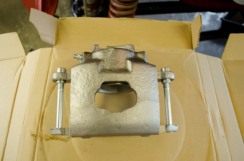
My calliper. | |||||||||||||||||||||||||||||||||||||||||||||
 |
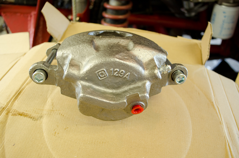
My calliper. | |||||||||||||||||||||||||||||||||||||||||||||
 |
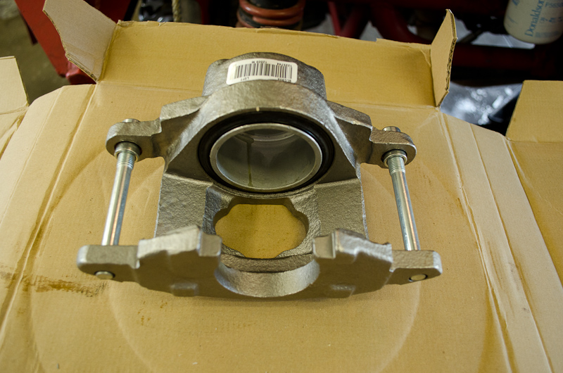
My calliper. | |||||||||||||||||||||||||||||||||||||||||||||
 |
My calliper. | |||||||||||||||||||||||||||||||||||||||||||||
PadsThere are a huge number of pads available that will work for this conversion. Obviously the pads matching the application or part number for the calliper you use will work. Also, each manufacturer usually makes 2-3 different types of pads for most of the applications in question. For example, Wagner make at least the following:
The pads for the standard callipers (metric or standard brake line) are the same. The pads for the HD Calliper are different. According to the Wagner online data, for their ThermoQuiet OE Semi-Metallic line of pads, the standard calliper pads have Friction Thickness of 0.6" (Inner Pad) and 0.54" (Outer Pad). The same pads for the larger HD calliper have Friction Thickness of 0.662" (Inner Pad) and 0.572" (Outer Pad). Not having handled or measured the HD calliper pads, I do not know if their are other differences or if they are at all interchangeable so I would recommend you stick with the pads intended for the callipers you use. Here are some Wagner Disc Brake Pad part numbers (each for set of 4 pads):
|
||||||||||||||||||||||||||||||||||||||||||||||
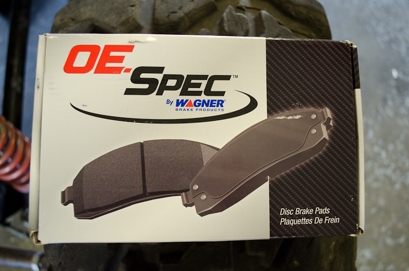 |
Here are the pads I used. | |||||||||||||||||||||||||||||||||||||||||||||
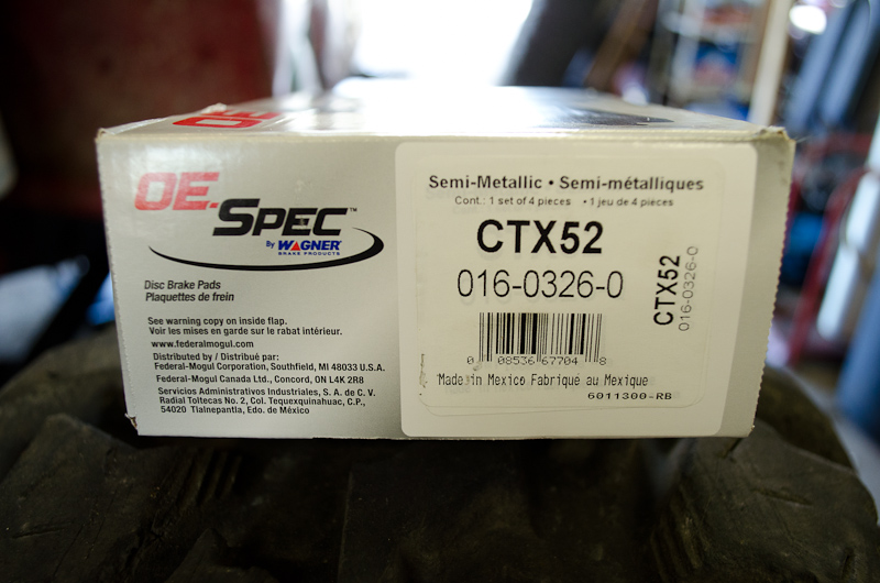 |
They're a cheap Wagner sub-brand, p/n: CTX52. I must have been in a cheap mood, probably still ticked-off at my last set of shredded pads which were good quality AC Delco parts. Cost me $36.99. |
|||||||||||||||||||||||||||||||||||||||||||||
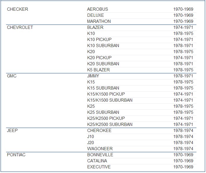
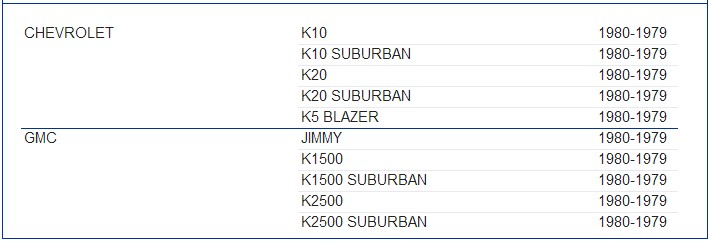
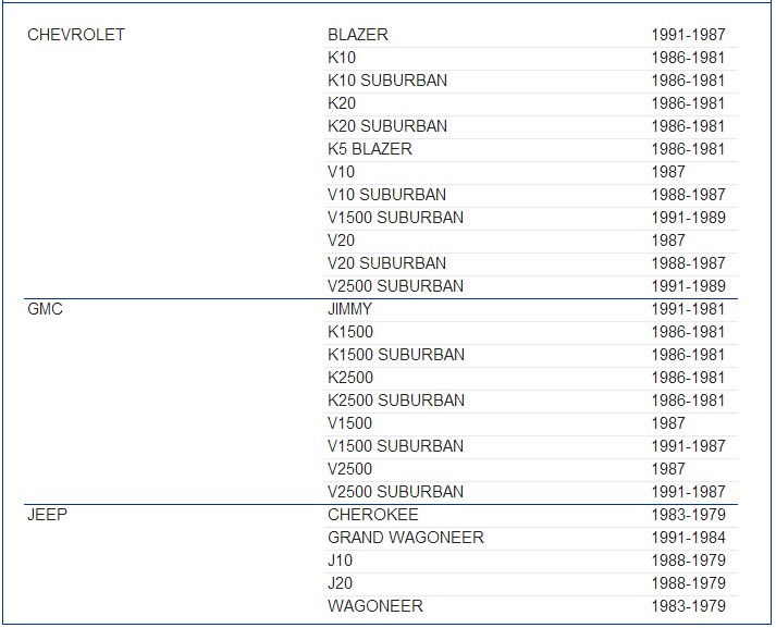
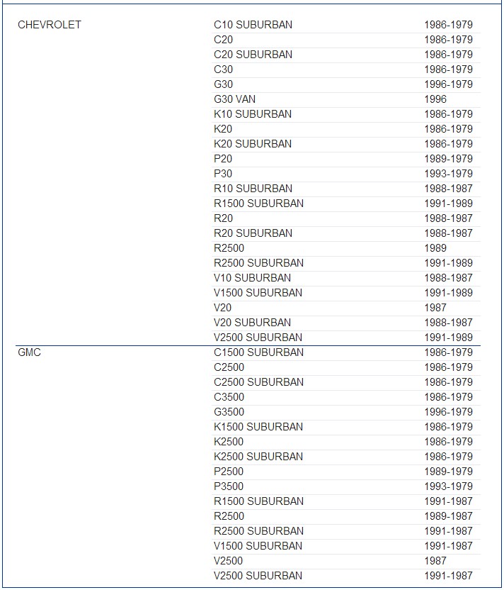
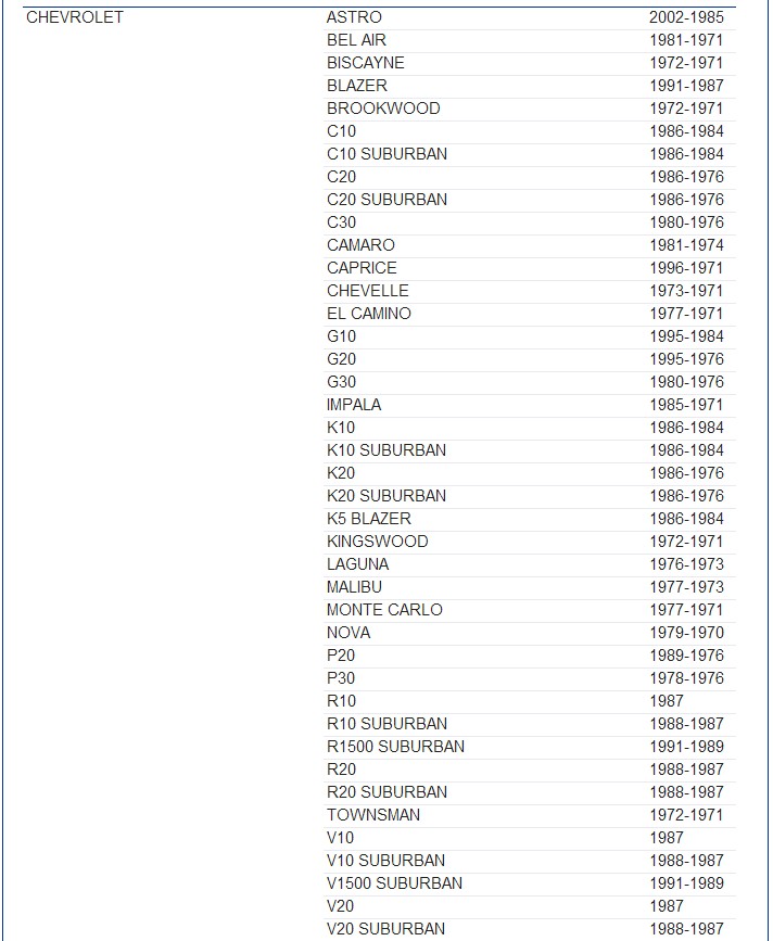
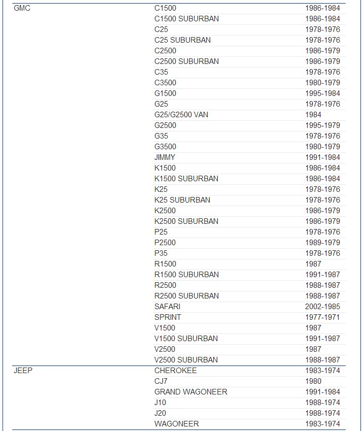
Just for interest, here's a list of applications that use the standard-calliper pads. It's ridiculously huge. So - no worries of the pads going out of service anytime soon!
RotorsThere are fewer rotor choices (thank god!) than for the callipers and pads, because obviously only applications with 8-lug axles will use 8-lug rotors that will fit the 14-Bolt axle. Here are some applications.
|
||||||||||||||||||||||||||||||||||||||||||||||
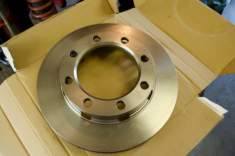 |
They are vented cast-iron rotors, 12.5" in diameter, 1.3" thick. | |||||||||||||||||||||||||||||||||||||||||||||
 |
This is the one I bought to replace my older ruined one. It's another Wagner sub-brand - Guardian, p/n: QLS 5523. Cost me $59.99. Frankly it's not very good quality. Normally I would buy a quality part like an AC Delco or Wagner. The Wagner part number is BD60427. AC Delco is 18A61. |
|||||||||||||||||||||||||||||||||||||||||||||
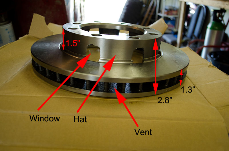 |
Good shot of the vents and the characteristic "windows" cut into the hat. These ones look like they were flame-cut by a drunk guy. The whole rotor is 2.8" thick, the discs 1.3" thick and the hat 1.5" thick. |
|||||||||||||||||||||||||||||||||||||||||||||
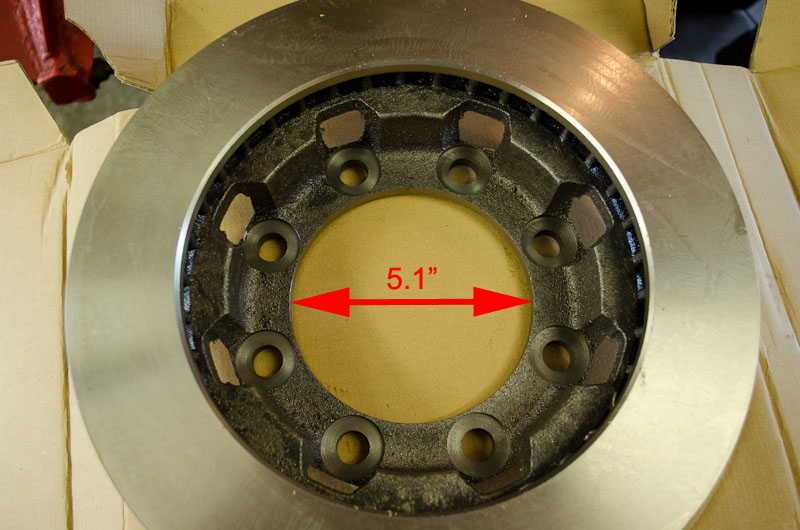 |
Inside of the rotor. The hub hole is 5.1". |
|||||||||||||||||||||||||||||||||||||||||||||
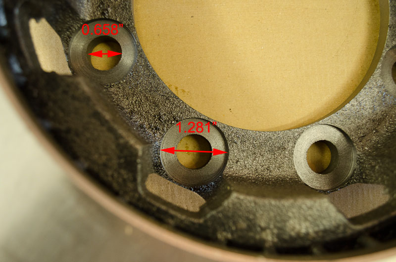 |
The holes for the studs are 0.658" (this will be important when we discuss stud choice in a moment). The recess where the head of the stud will sit is 1.281" in diameter. |
|||||||||||||||||||||||||||||||||||||||||||||
Wheel Studs |
||||||||||||||||||||||||||||||||||||||||||||||
 |
The wheel studs are used to pin or "stake" the new rotor to the back side of the wheel hub, in the same fashion they staked the old drum to the hub, like this. | |||||||||||||||||||||||||||||||||||||||||||||
 |
The stock stud is:
with the following dimensions: |
|||||||||||||||||||||||||||||||||||||||||||||
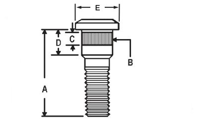 |
Thread: 9/16"-18 R Length (A): 3" Knurl Dia (B): 0.625" * Knurl Length (C): 0.875" Shoulder Length (D): 1.700" Head Diameter (E): 1.108" |
|||||||||||||||||||||||||||||||||||||||||||||
* Note: Papco list the knurl diameter as 0.630", Doorman list it as 0.622". I measured it at 0.620" - 0.625". I'm going to use 0.625" as an average. But there are three problems with reusing the old studs from the original drum setup. Compared to the old drum, the mounting flange on the new rotor hat is thicker and the diameter of the stud holes is larger. The result is: the old studs are too short, the knurled section is too small in diameter, and the knurled section is also a little too short to completely stake the rotor and hub together. So, ideally, we need a stud that is longer and has a longer and larger diameter knurled section. Let's take a look at the numbers
Looking at the numbers (bold text), we can see that there's another problem. While the stud hole in the new rotor is larger, obviously the holes in the hub are not. Therefore, if we used a stud with a large enough knurl diameter to fit snugly in the rotor hole, it wouldn't go through the hole in the hub. So, we have three options: Option 1: We could find the closest suitable stud and have the holes in the wheel hub machined out to the same diameter as the rotor holes. Since the rotor hole is 0.658" and we are staking the rotor and drum together, we need a class V interference fit (press fit) which necessitates a knurled section 10-20 thou larger than the hole - as is the case with the stock stud which is about 17 thou larger than the hub hole. So we'd need a 9/16-18 stud, at least 3.5 long, with a knurl diameter of between 0.668 - 0.678, and a knurl length of at least 0.75". |
||||||||||||||||||||||||||||||||||||||||||||||
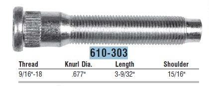 |
The closest to that available is:
with the following dimensions:
|
|||||||||||||||||||||||||||||||||||||||||||||
|
Thread: 9/16"-18 R Length (A): 3-9/32" Knurl Dia (B): 0.677" Knurl Length (C): 0.435" Shoulder Length (D): 0.725" (Papco) / 0.9375" (Dorman) Head Diameter (E): ? (pretty small) |
|||||||||||||||||||||||||||||||||||||||||||||
So this stud has the right thread, overall length, and the critical knurl diameter. But the problem is the short knurl length, short shoulder length, and the positioning of the knurl right up under the head. This means the knurl would be a nice tight fit in the rotor, but there would be no knurl length to engage the hub - not good for staking the two together and certainly not worth machining hubs for. Also, the shoulder itself is pretty short and would only go into the hub hole by about a 1/4" or so. And to top it off I wouldn't be crazy about the small head sitting in the recess on the back of the rotor. So - scratch option 1 - too much work and expense to machine the hubs for what would be a lousy solution in the end anyway. Option 2: We could find the closest suitable stud and have it machined or custom studs made to the required specifications. I discarded this option right away as being too expensive and impractical. To start with,in order to machine a stock stud, you'd have to start with one with a knurl diameter large enough to be a press fit into the rotor hole - and the only one of those is the one we mentioned above and it wouldn't work well for the reasons we already discussed. The only other option would be to start with a long-enough larger stud like a 5/8-18 that has an appropriate knurl and shoulder, and have the threads re-cut. Only two problems: 1- there aren't any and 2- in my opinion, re-cutting the threads from 5/8 to 9/16 is not a good idea on something that has the nuts on and off, and as tightly, as wheel studs. That leaves having completely new custom studs made - which has three problems: 1- How many places are able to do that? 2- It would be expensive, and 3- you would still be left with a major design flaw, namely that there would be a radius change in the stud (and therefore a natural stress riser) right were the shear-plane is between the rotor and the hub. As my old hero Carl Smith would succinctly say - dumb! Option 3: So that leaves only one realistic option - find the closest suitable stud and live with the imperfections of the design.There are two possible studs that might fit the bill here, neither of them perfect, both with their own drawbacks (actually three if we consider metric equivalents, but let's just focus on the standard-thread choices and look at the metric option later). |
||||||||||||||||||||||||||||||||||||||||||||||
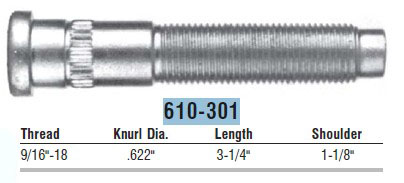 |
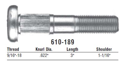
The closest to that available is:
with the following dimensions: |
|||||||||||||||||||||||||||||||||||||||||||||
|
Thread: 9/16"-18 R Length (A): 3.25 " Knurl Dia (B): 0.622" Knurl Length (C): 0.225" (about 0.4" from the underside of the head) Shoulder Length (D): 1.125" Head Diameter (E): ? (pretty small) |
|||||||||||||||||||||||||||||||||||||||||||||
So, this stud has the right thread, and the knurl is a good diameter to fit snugly in the hub hole. Also, the smooth shoulder between the underside of the head and the beginning of the knurl is about 0.7" in diameter - making it a good snug fit for the hole in the rotor (about 10 thou larger than the hole). The problem is the very short length of the knurl and its position on the shoulder. |
||||||||||||||||||||||||||||||||||||||||||||||
 |
Consider that: The rotor flange is 0.5" thick. And we can see that the knurl will barely engage the hub, maybe no more than 1/8" at best. |
|||||||||||||||||||||||||||||||||||||||||||||
And the problem with that is, it puts the stud at pretty good risk of spinning when the lug nuts are done up or removed - especially since the fit between the shoulder and the rotor is smooth and not knurled. So the stud is good for centering the hub and rotor together with the two different size holes, but it's hardly ideal since it essentially trades a poor fit in the rotor (stock stud) for a poor fit in the hub. Plus, at only 3.25" long, it's really not quite as long as we would like. So that brings us to the final option, and the one I chose. |
||||||||||||||||||||||||||||||||||||||||||||||
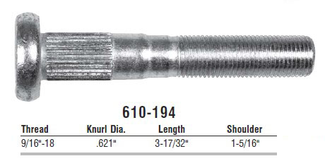 |
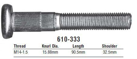
This stud is part number:
with the following dimensions: |
|||||||||||||||||||||||||||||||||||||||||||||
|
Thread: 9/16"-18 R Length (A): 3-17/32" Knurl Dia (B): 0.630" Knurl Length (C): 0.875 Shoulder Length (D): 1.675" Head Diameter (E): 1.108" |
|||||||||||||||||||||||||||||||||||||||||||||
| This stud has the right thread, great length, good knurl diameter to press-fit in the hub hole, and a good head diameter. It's problems are that the knurl will be sloppy in the rotor hole (like the stock stud) and that the knurl length is a little short for ideal engagement in the hub hole, because of the thickness of he rotor flange. | ||||||||||||||||||||||||||||||||||||||||||||||
 |
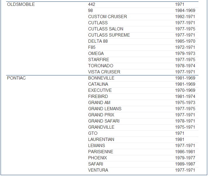
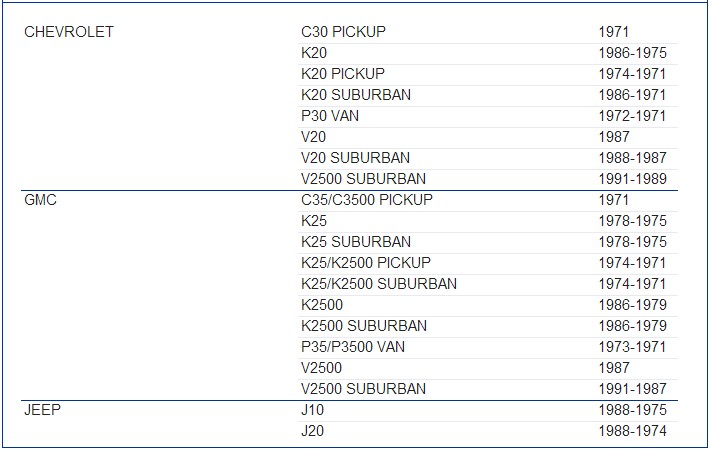
In other words, it is just a 17/32" longer version of the stock stud. Here's a picture of this stud next to the stock stud. It can be found in the following applications: 1975-1986 Chevrolet C30 2WD 1-Ton Pickup with DRW & Drum Brakes 1979-1986 Chevrolet K30 4WD 1-Ton Pickup with DRW & Drum Brakes 1994-1995 Chevrolet C3500 2WD 1-Ton Pickup with DRW & Drum Brakes |
|||||||||||||||||||||||||||||||||||||||||||||
So, this is the best compromise in my opinion (or at least the least objectionable). But it does leave the problem of the rotor being sloppy on the stud, which means that as you drive the studs through the rotor and hub, it can be difficult to maintain the rotor perfectly centred and aligned to the hub. Here's a video that shows the issue:
Not great, but not the end of the world either. Now - before we move on, there is just one stud to look at - the metric one I mentioned earlier. |
||||||||||||||||||||||||||||||||||||||||||||||
 |
This stud is part number:
with the following dimensions: |
|||||||||||||||||||||||||||||||||||||||||||||
|
Thread: M14 x 1.5R Length (A): 91mm Knurl Dia (B): 15.7mm Knurl Length (C): 22mm Shoulder Length (D): 33mm Head Diameter (E): 28mm |
|||||||||||||||||||||||||||||||||||||||||||||
It is essentially the metric version of the previous stud, used in later-model versions of the same trucks, as metric parts began to creep in more and more. It can be found in the following applications: 1988-1998 Chevrolet C3500 2WD 1-Ton Pickup with DRW & Drum Brakes 1988-1998 Chevrolet K3500 4WD 1-Ton Pickup with DRW & Drum Brakes I ended up actually using this metric wheel stud since the local parts place didn't have any in standard-thread and I was in a hurry. |
||||||||||||||||||||||||||||||||||||||||||||||
|
So, the rotor goes on the back of the hub like this. | |||||||||||||||||||||||||||||||||||||||||||||
 |
Then align the rotor and hub holes... | |||||||||||||||||||||||||||||||||||||||||||||
 |
...and drive the studs through the rotor and into the hub... | |||||||||||||||||||||||||||||||||||||||||||||
 |
...using a brass drift and big hammer. | |||||||||||||||||||||||||||||||||||||||||||||
Wheel Nuts |
||||||||||||||||||||||||||||||||||||||||||||||
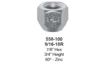 |
You can use a regular wheel-nut like this one. Papco part number: 558-100 It has the following dimensions: |
|||||||||||||||||||||||||||||||||||||||||||||
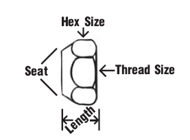 |
Hex Size: 7/8" Thread Size: 9/16-18 Length: 3/4" Seat: 60° taper. Finish: Zinc plated. |
|||||||||||||||||||||||||||||||||||||||||||||
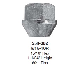 |
But I prefer this style, which is known as a "bulge" style wheel nut. Papco part number 558-062. I like the nice big cone seat, I like the extra length to protect more of the wheel stud threads, I like the fact that there's a positive stop for the socket provided by the lip between the hex and the cone seat, and I also like that they are just bigger, heavier, and meatier. This one has the following dimensions: |
|||||||||||||||||||||||||||||||||||||||||||||
|
Hex Size: 15/16" Thread Size: 9/16-18 Length: 1-1/64" Seat: 60° taper. Finish: Zinc plated. |
|||||||||||||||||||||||||||||||||||||||||||||
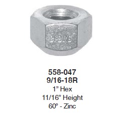 |
Another option is a big 1" hex nut, like this Papco part number 558-047. It has the following dimensions: |
|||||||||||||||||||||||||||||||||||||||||||||
|
Hex Size: 1" Thread Size: 9/16-18 Length: 11/16" Seat: 60° taper. Finish: Zinc plated. |
|||||||||||||||||||||||||||||||||||||||||||||
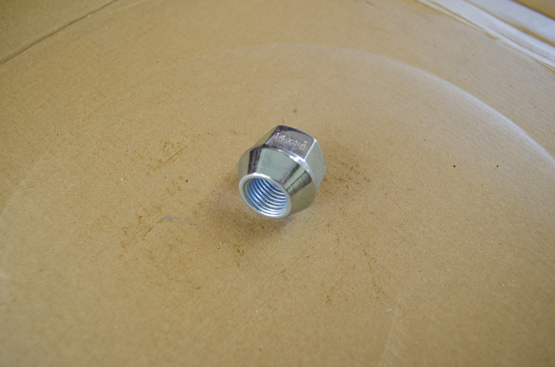 |
Because I am using metric-thread wheel studs, obviously I must use a metric wheel nut. This is Papco (H. Paulin & Co. Limited) part number 559-154. For my fellow Canadians, you can get them as Canadian Tire p/n: 4X013-9727-8 (cost $2.49 ea.) The dimensions are: |
|||||||||||||||||||||||||||||||||||||||||||||
|
Hex Size: 22mm. Thread Size: M14 x 1.5 Length: 21mm. Seat: 60° taper. Finish: Zinc plated. |
|||||||||||||||||||||||||||||||||||||||||||||
In case your needs, design, or wants differ from those that I've described in this article, you can always browse the following catalogs for different options for wheel studs and wheel nuts. Dorman Wheel Studs and Nuts Catalog Papco Wheel Parts (Hardware) - 2009 Catalog Putting it all TogetherOK, so now we have all our parts choices made, it's time to complete the project. |
||||||||||||||||||||||||||||||||||||||||||||||
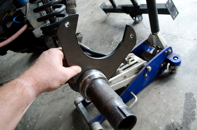 |
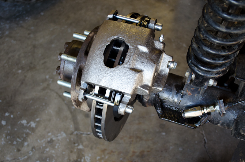
We need to get the calliper bracket welded on the 14-Bolt spindle in about this position, making sure that we get the calliper mounted as high up as possible to keep it out of the rocks, while still keeping the bleeder screw mounted at the top (otherwise we have to take the calliper off and stick a block of wood in it and hold it with the bleeder up every time we bleed the brakes - which is an enormous pain in the ass). |
|||||||||||||||||||||||||||||||||||||||||||||
 |
And we have to get the bracket perfectly positioned and square to the axle - otherwise it all goes badly wrong as shown at the beginning of the article. | |||||||||||||||||||||||||||||||||||||||||||||
 |
First, install the hub and rotor onto the spindle, and adjust the wheel bearings. No need to install the axle shafts at this time. | |||||||||||||||||||||||||||||||||||||||||||||
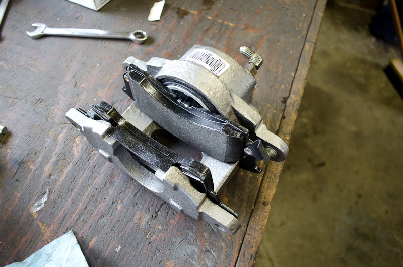 |
Next install the pads and abutment clip in the calliper, as well as the brake line fitting (here I am using a 7/16-NF ORB to -4 AN 90* conversion fitting) | |||||||||||||||||||||||||||||||||||||||||||||
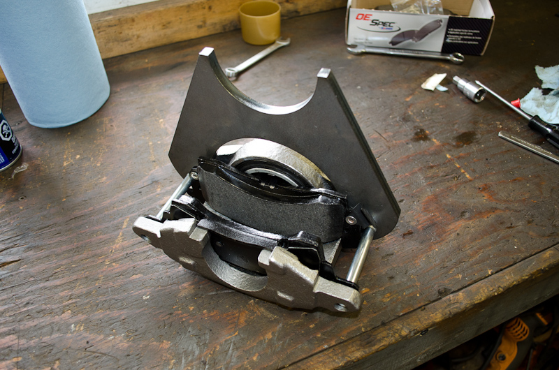 |
Then bolt the bracket to the calliper... | |||||||||||||||||||||||||||||||||||||||||||||
 |
...like this. | |||||||||||||||||||||||||||||||||||||||||||||
 |
Making sure it is snugged up with the bracket right up next to the calliper. | |||||||||||||||||||||||||||||||||||||||||||||
 |
Place the bracket in place on the spindle with the calliper over the rotor. | |||||||||||||||||||||||||||||||||||||||||||||
 |
Then connect the brake line up and rotate the calliper into position. Wire or bungee the bracket/calliper in this position so you can bleed the brakes. Then go ahead and bleed the brakes. Once you are done bleeding the brakes, double check the bracket position is right for positioning the calliper where you want, then have someone firmly apply the brake and hold it there. |
|||||||||||||||||||||||||||||||||||||||||||||
| This is the key to getting everything spaced and squared properly. You can muck around with spacers and such, but those don't hold everything nice and firm while you tack weld the bracket in place. I have fo9und it is well worth the effort to hook up the brake lines and bleed the brakes - then you can be sure everything is in the right position, and the brake pedal will hold it all nice and firmly in place. | ||||||||||||||||||||||||||||||||||||||||||||||
 |
With the pedal held down firmly, tack the bracket in place. Then release the brake, undo the brake line, remove the calliper, and take the hub and rotor off again. |
|||||||||||||||||||||||||||||||||||||||||||||
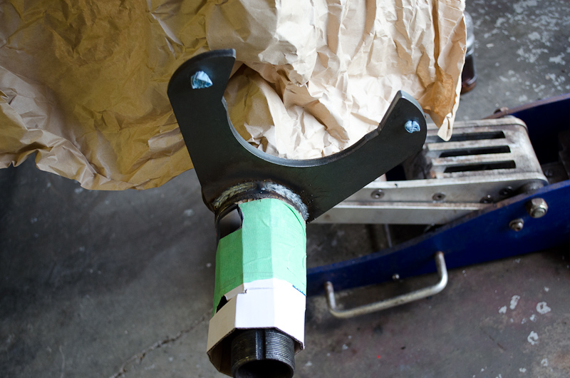 |
Cover the spindle to protect the threads and bearing / seal surfaces (they don't do well with weld splatter). And carefully weld the bracket in place. Take your time and weld a little at a time on each side - you do not want to warp the bracket with weld heat at this point and ruin the alignment. Let it cool, clean any splatter, throw on some paint, and let the paint dry. |
|||||||||||||||||||||||||||||||||||||||||||||
 |
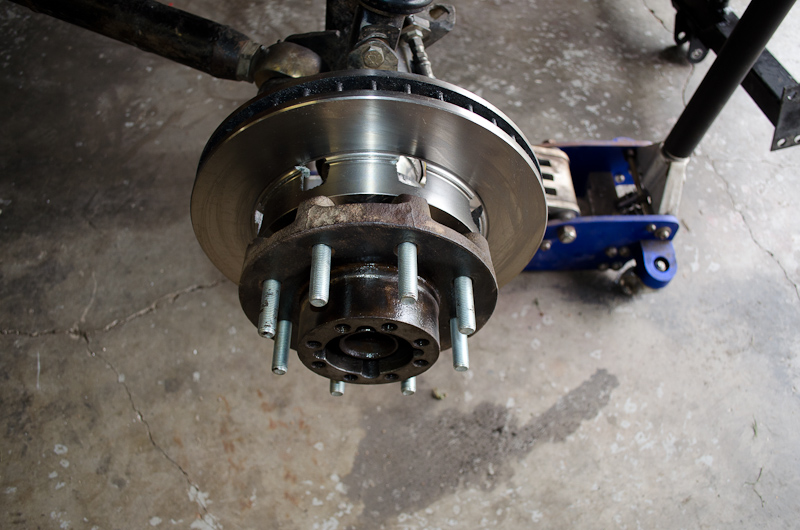
Then you just need to slap the hub and rotor back on, adjust the wheel bearings, install the axle shafts... | |||||||||||||||||||||||||||||||||||||||||||||
|
... install the calliper and pads... | |||||||||||||||||||||||||||||||||||||||||||||
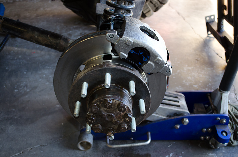
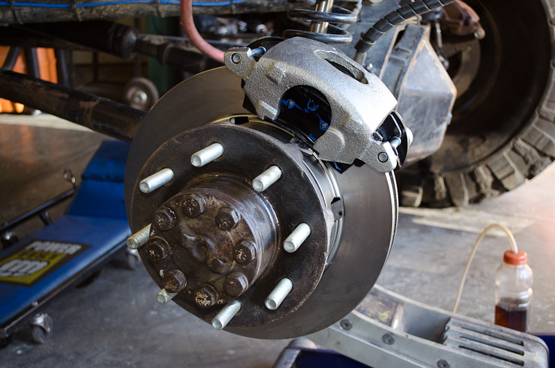 |
reconnect the brake line, bleed the brakes, and...you are done! There are 1.743" of threads protruding from the wheel mounting surface of the hub. |
|||||||||||||||||||||||||||||||||||||||||||||
 |
So, if we allow a half inch for the wheel flange, and an inch for the wheel nut legth, we still have a quarter inch left, sticking through the wheel nut (that's about 5 threads at 18TPI) Much better thread engagement of the wheel nuts now... |
|||||||||||||||||||||||||||||||||||||||||||||
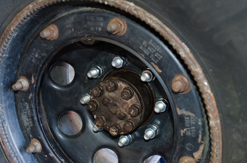 |
...in fact, enough thread remaining to run aluminum wheels with thick mounting flanges. MISSION ACCOMPLISHED! |
|||||||||||||||||||||||||||||||||||||||||||||
|
||||||||||||||||||||||||||||||||||||||||||||||

|