 |
The Automotive Plumbing Bible By Bill "BillaVista" Ansell |
What is plumbing (in the automotive sense)?Simply speaking, plumbing is the collection of components involved in moving a fluid from one place to another. The fluid could be a liquid (fuel, coolant, etc.) or a gas (compressed air, etc.). There may be many different reasons we need to move a fluid from one place to another – it could be to cool the fluid, or it could be so the fluid can do some work - as in fuel moved from a tank to an engine. What all plumbing shares in common is that its importance is often overlooked. |
 |
Why is plumbing important?Why is plumbing important? The fact is, any piece of machinery, and particularly a vehicle subjected to the rigours of offroad or racing use, is a collection of inter-operating components – and failure of any of those components often means failure of the machine. Whether that failure results in a ruined weekend adventure or the loss of a checkered flag, it is something we wish to avoid. Whatever the machine in question, it is only as reliable as its weakest link. If the weakest link fails, the machine fails. In a vehicle, there are so many systems that rely on fluid movement that, combined with the tendency for folks to overlook the importance of something as seemingly “simple” as plumbing, odds are a plumbing failure will strike all of us at some point. But it doesn’t have to – and this article is all about, as much as possible, avoiding that failure. Part of the problem with plumbing is that it is given little respect or thought. All too often it seems as if it would be easy (and cheap) to just use any old piece of hose and a hardware-store fitting to plumb something on the car. Sure, you could do this, and many do. We tend to find these people broken down and blocking the trail or sitting dejected in the pits. In fact, I would venture a guess that plumbing failure is one of the most common contributors to unnecessary failures and breakdowns. On the other hand, plumbing success need not be difficult or overly expensive – all it takes is a little knowledge compared with some care and thought. For example, which would you say is the most important component in your car: … is it the engine that produces the power? The answer is: all of them. When any one of these components fails, the machine fails – or at the very least is unable to operate at peak performance or efficiency. Since none of the components can be allowed to fail, they are all equally important! As a result – the car’s plumbing deserves every bit as much care and attention in its selection, fabrication, installation, use, and maintenance as any other part of the car! The above example deals with just a couple of systems on the car – but there are many others where plumbing is an important factor, including:
So, plumbing is important and not to be overlooked. Basic ComponentsThe basic components of any plumbing system are relatively few and straightforward. Essentially, you have:
Let’s have a look at each now, and cover them each in greater detail later. LinesFluid lines can be pipe, tube, or hose. Pipe is rigid, heavy, and normally joined by threading, soldering, or welding. The water plumbing in your house is normally pipe. It is unsuitable for automotive use and so we will say no more about it, except that if someone says “pipe” in relation to automotive plumbing they probably mean “tube”. |
|
Russell Performance Aluminum Fuel Line (tubing) |
Tube is semi-rigid, lightweight, and can be joined with a large array of fittings. Brake “hardlines” are a common example of the use of tube in automotive plumbing. Being semi-rigid, it can easily be bent by using specialized hand tools. Although it can be bent by hand, tube is not truly “flexible” and must be secured along its length and not allowed to “flex” between components. Although cheaper than hose, it is more difficult to install and normally more challenging to join (often requiring the tubing to be “flared” for use with tube fittings). Tube may be made of steel, stainless steel, aluminum, or copper – each with its own properties.
|
||||||||||||||||||||||||||||||||||||||||||||||||||||||||||||||||||||||||||||||||||||||||||||||||||||||||||||||||||||||||||||||||||||||||||||||||||||||||||||||||||||||||||||||||||||||||||||||||||||||||||||||||||||||||||||||||||||||||||||||||||||||||||||||||||||||||||||||||||||||||||||||||||||||||||||||||||||||||||||||||||||||||||||||||||||||||||||||||||||||||||||||||||||||||||||||||||||||||||||||||||||||||||||||||||||||||||||||||||||||||||||||||||||||||||||||||||||||||||||||||||||||||||||||||||||||||||||||||||||||||||||||||||||||||||||||||||||||||||||||||||||||||||||||||||||||||||||||||||||||||||||||||||||||||||||||||||||||||||||||||||||||||||||||||||||||||||||||||||||||||||||||||||||||||||||||||||||||||||||||||||||||||||||||||||||||||||||||||||||||||||||||||||||||||||||||||||||||||||||||||||||||||||||||||||||||||||||||||||||||||||||||||||||||||||||||||||||||||||||||||||||||||||||||||||||||||||||||||||||||||||||||||||||||||||||||||||||||||||||||||||||||||||||||||||||||||||||||||||||||
Russell Performance Proflex Hose |
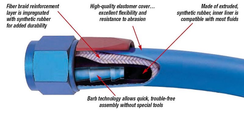
Hose is flexible, relatively lightweight, and can be constructed of many different materials depending on the nature of the fluid to be conveyed. It can be used with crimped-on or re-usable “field attachable” hose-ends. A quality automotive hose will be constructed of multiple layers to maximize it’s vibration resistance, chemical compatibility, temperature resistance, flexibility, and abrasion & corrosion resistance. Hose is essential for use with components between which there is even the slightest relative movement. | ||||||||||||||||||||||||||||||||||||||||||||||||||||||||||||||||||||||||||||||||||||||||||||||||||||||||||||||||||||||||||||||||||||||||||||||||||||||||||||||||||||||||||||||||||||||||||||||||||||||||||||||||||||||||||||||||||||||||||||||||||||||||||||||||||||||||||||||||||||||||||||||||||||||||||||||||||||||||||||||||||||||||||||||||||||||||||||||||||||||||||||||||||||||||||||||||||||||||||||||||||||||||||||||||||||||||||||||||||||||||||||||||||||||||||||||||||||||||||||||||||||||||||||||||||||||||||||||||||||||||||||||||||||||||||||||||||||||||||||||||||||||||||||||||||||||||||||||||||||||||||||||||||||||||||||||||||||||||||||||||||||||||||||||||||||||||||||||||||||||||||||||||||||||||||||||||||||||||||||||||||||||||||||||||||||||||||||||||||||||||||||||||||||||||||||||||||||||||||||||||||||||||||||||||||||||||||||||||||||||||||||||||||||||||||||||||||||||||||||||||||||||||||||||||||||||||||||||||||||||||||||||||||||||||||||||||||||||||||||||||||||||||||||||||||||||||||||||||||||||
Hose AssemblyA hose with hose-ends connected to it is known as a “hose assembly”. The most important thing to remember when constructing hose assemblies is to match the ratings of the hose and the hose-ends. It is possible to assemble a hose assembly with a hose-end(s) that have a performance rating (temperature or pressure rating) lower than the rating of the hose. Overall hose assembly performance will be limited to the lowest rating of the individual components used. Hose assemblies can be built at home using bulk hose and field-attachable hose-ends or they can be custom ordered from a manufacturer with crimped-on hose-ends. If ordering complete, crimped hose-end hose assemblies, the end user must pay very careful attention to the length ordered. Normally hose assembly lengths will be specified as either:
We shall detail later in the article the process of creating your own custom-length hose assemblies using Russell Performance Proflex hose and full-flow aluminum filed-attachable AN hose-ends. FittingsThe term "fittings" refers collectively to hose-ends, adapters, unions, and other small hard parts of the plumbing system. In general, fittings are used to join the lines together and to join the lines to the necessary components. Industrial fittings can be made of steel, brass, or aluminum but quality automotive fittings are almost exclusively aluminum. |
|||||||||||||||||||||||||||||||||||||||||||||||||||||||||||||||||||||||||||||||||||||||||||||||||||||||||||||||||||||||||||||||||||||||||||||||||||||||||||||||||||||||||||||||||||||||||||||||||||||||||||||||||||||||||||||||||||||||||||||||||||||||||||||||||||||||||||||||||||||||||||||||||||||||||||||||||||||||||||||||||||||||||||||||||||||||||||||||||||||||||||||||||||||||||||||||||||||||||||||||||||||||||||||||||||||||||||||||||||||||||||||||||||||||||||||||||||||||||||||||||||||||||||||||||||||||||||||||||||||||||||||||||||||||||||||||||||||||||||||||||||||||||||||||||||||||||||||||||||||||||||||||||||||||||||||||||||||||||||||||||||||||||||||||||||||||||||||||||||||||||||||||||||||||||||||||||||||||||||||||||||||||||||||||||||||||||||||||||||||||||||||||||||||||||||||||||||||||||||||||||||||||||||||||||||||||||||||||||||||||||||||||||||||||||||||||||||||||||||||||||||||||||||||||||||||||||||||||||||||||||||||||||||||||||||||||||||||||||||||||||||||||||||||||||||||||||||||||||||||||
Russell Performance Aluminum Full-flow hose-end |
Hose-EndsHose-ends, also called couplings, are the parts that are crimped or screwed onto the ends of hose or tubing so that the lines may be joined to the necessary components. There are several different types common in automotive plumbing, each of which we shall examine in great detail a little later. |
||||||||||||||||||||||||||||||||||||||||||||||||||||||||||||||||||||||||||||||||||||||||||||||||||||||||||||||||||||||||||||||||||||||||||||||||||||||||||||||||||||||||||||||||||||||||||||||||||||||||||||||||||||||||||||||||||||||||||||||||||||||||||||||||||||||||||||||||||||||||||||||||||||||||||||||||||||||||||||||||||||||||||||||||||||||||||||||||||||||||||||||||||||||||||||||||||||||||||||||||||||||||||||||||||||||||||||||||||||||||||||||||||||||||||||||||||||||||||||||||||||||||||||||||||||||||||||||||||||||||||||||||||||||||||||||||||||||||||||||||||||||||||||||||||||||||||||||||||||||||||||||||||||||||||||||||||||||||||||||||||||||||||||||||||||||||||||||||||||||||||||||||||||||||||||||||||||||||||||||||||||||||||||||||||||||||||||||||||||||||||||||||||||||||||||||||||||||||||||||||||||||||||||||||||||||||||||||||||||||||||||||||||||||||||||||||||||||||||||||||||||||||||||||||||||||||||||||||||||||||||||||||||||||||||||||||||||||||||||||||||||||||||||||||||||||||||||||||||||||
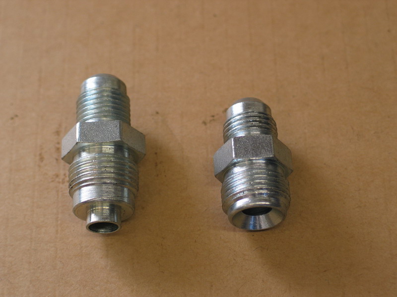
Russell Performance NPT (pipe) to AN adapter |
AdaptersAdapters are fittings that are used to connect other components that do not have common styles. They may be used to join hose-ends of differing types or sizes, or they may be used to connect a port of one style or size to a hose-end of a different style or size. For example, if you have an oil cooler with ½” NPT ports and are using oil cooler lines constructed from -10 stainless steel braided hose with -10 AN hose-ends, you would use a “½”NPT to -10 AN” adapter. Basically an adapter “adapts” one size or style of fitting to another size and/or style. |
||||||||||||||||||||||||||||||||||||||||||||||||||||||||||||||||||||||||||||||||||||||||||||||||||||||||||||||||||||||||||||||||||||||||||||||||||||||||||||||||||||||||||||||||||||||||||||||||||||||||||||||||||||||||||||||||||||||||||||||||||||||||||||||||||||||||||||||||||||||||||||||||||||||||||||||||||||||||||||||||||||||||||||||||||||||||||||||||||||||||||||||||||||||||||||||||||||||||||||||||||||||||||||||||||||||||||||||||||||||||||||||||||||||||||||||||||||||||||||||||||||||||||||||||||||||||||||||||||||||||||||||||||||||||||||||||||||||||||||||||||||||||||||||||||||||||||||||||||||||||||||||||||||||||||||||||||||||||||||||||||||||||||||||||||||||||||||||||||||||||||||||||||||||||||||||||||||||||||||||||||||||||||||||||||||||||||||||||||||||||||||||||||||||||||||||||||||||||||||||||||||||||||||||||||||||||||||||||||||||||||||||||||||||||||||||||||||||||||||||||||||||||||||||||||||||||||||||||||||||||||||||||||||||||||||||||||||||||||||||||||||||||||||||||||||||||||||||||||||||
Russell Performance -10AN to -10AN union |
UnionsA union is a special type of adapter used to join hose-ends or to join a port and a hose-end when both parts being joined are the same size and style. If you wanted to connect two hoses, both using -10AN hose-ends, you would use a “-10AN to -10AN union”. |
||||||||||||||||||||||||||||||||||||||||||||||||||||||||||||||||||||||||||||||||||||||||||||||||||||||||||||||||||||||||||||||||||||||||||||||||||||||||||||||||||||||||||||||||||||||||||||||||||||||||||||||||||||||||||||||||||||||||||||||||||||||||||||||||||||||||||||||||||||||||||||||||||||||||||||||||||||||||||||||||||||||||||||||||||||||||||||||||||||||||||||||||||||||||||||||||||||||||||||||||||||||||||||||||||||||||||||||||||||||||||||||||||||||||||||||||||||||||||||||||||||||||||||||||||||||||||||||||||||||||||||||||||||||||||||||||||||||||||||||||||||||||||||||||||||||||||||||||||||||||||||||||||||||||||||||||||||||||||||||||||||||||||||||||||||||||||||||||||||||||||||||||||||||||||||||||||||||||||||||||||||||||||||||||||||||||||||||||||||||||||||||||||||||||||||||||||||||||||||||||||||||||||||||||||||||||||||||||||||||||||||||||||||||||||||||||||||||||||||||||||||||||||||||||||||||||||||||||||||||||||||||||||||||||||||||||||||||||||||||||||||||||||||||||||||||||||||||||||||||
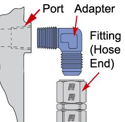 |
PortsI use the term “ports” to refer to the holes into which hose-ends, adapters, or other fittings must fit. Depending on the component in question, they may be a straight hole in which a “bulkhead fitting” is used, or they may be threaded holes such as the oil line ports in an engine block or transmission casting. Normally, when plumbing a car one uses the necessary adapters and hose-ends to fit the existing ports in the components. However, if fabricating highly customized components, the plumber may be faced with a choice of what type of port to create. In this case, I have included some discussion on the matter in the sections on individual hose-end types and thread tapping. Essentially, the easiest port to construct is a straight hole in which a “bulkhead fitting” is used, the next simplest is probably some sort of female tapered pipe thread drilled and tapped, and the most difficult, but best, would be a port that uses a machined seat for an elastomeric seal such as an O-ring. |
||||||||||||||||||||||||||||||||||||||||||||||||||||||||||||||||||||||||||||||||||||||||||||||||||||||||||||||||||||||||||||||||||||||||||||||||||||||||||||||||||||||||||||||||||||||||||||||||||||||||||||||||||||||||||||||||||||||||||||||||||||||||||||||||||||||||||||||||||||||||||||||||||||||||||||||||||||||||||||||||||||||||||||||||||||||||||||||||||||||||||||||||||||||||||||||||||||||||||||||||||||||||||||||||||||||||||||||||||||||||||||||||||||||||||||||||||||||||||||||||||||||||||||||||||||||||||||||||||||||||||||||||||||||||||||||||||||||||||||||||||||||||||||||||||||||||||||||||||||||||||||||||||||||||||||||||||||||||||||||||||||||||||||||||||||||||||||||||||||||||||||||||||||||||||||||||||||||||||||||||||||||||||||||||||||||||||||||||||||||||||||||||||||||||||||||||||||||||||||||||||||||||||||||||||||||||||||||||||||||||||||||||||||||||||||||||||||||||||||||||||||||||||||||||||||||||||||||||||||||||||||||||||||||||||||||||||||||||||||||||||||||||||||||||||||||||||||||||||||||
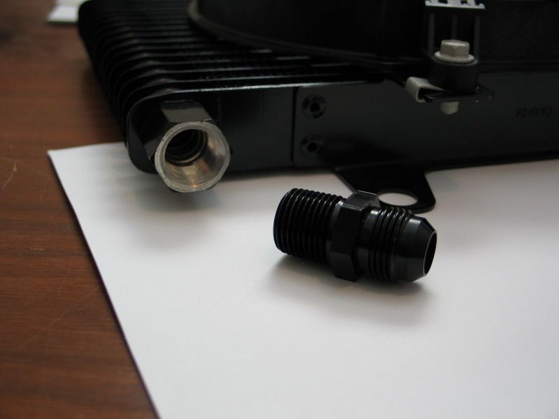 |
Oil cooler with NPT port and an NPT to AN adapter. | ||||||||||||||||||||||||||||||||||||||||||||||||||||||||||||||||||||||||||||||||||||||||||||||||||||||||||||||||||||||||||||||||||||||||||||||||||||||||||||||||||||||||||||||||||||||||||||||||||||||||||||||||||||||||||||||||||||||||||||||||||||||||||||||||||||||||||||||||||||||||||||||||||||||||||||||||||||||||||||||||||||||||||||||||||||||||||||||||||||||||||||||||||||||||||||||||||||||||||||||||||||||||||||||||||||||||||||||||||||||||||||||||||||||||||||||||||||||||||||||||||||||||||||||||||||||||||||||||||||||||||||||||||||||||||||||||||||||||||||||||||||||||||||||||||||||||||||||||||||||||||||||||||||||||||||||||||||||||||||||||||||||||||||||||||||||||||||||||||||||||||||||||||||||||||||||||||||||||||||||||||||||||||||||||||||||||||||||||||||||||||||||||||||||||||||||||||||||||||||||||||||||||||||||||||||||||||||||||||||||||||||||||||||||||||||||||||||||||||||||||||||||||||||||||||||||||||||||||||||||||||||||||||||||||||||||||||||||||||||||||||||||||||||||||||||||||||||||||||||||
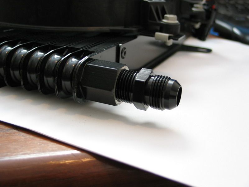 |
NPT to AN adapter fitted into NPT port. | ||||||||||||||||||||||||||||||||||||||||||||||||||||||||||||||||||||||||||||||||||||||||||||||||||||||||||||||||||||||||||||||||||||||||||||||||||||||||||||||||||||||||||||||||||||||||||||||||||||||||||||||||||||||||||||||||||||||||||||||||||||||||||||||||||||||||||||||||||||||||||||||||||||||||||||||||||||||||||||||||||||||||||||||||||||||||||||||||||||||||||||||||||||||||||||||||||||||||||||||||||||||||||||||||||||||||||||||||||||||||||||||||||||||||||||||||||||||||||||||||||||||||||||||||||||||||||||||||||||||||||||||||||||||||||||||||||||||||||||||||||||||||||||||||||||||||||||||||||||||||||||||||||||||||||||||||||||||||||||||||||||||||||||||||||||||||||||||||||||||||||||||||||||||||||||||||||||||||||||||||||||||||||||||||||||||||||||||||||||||||||||||||||||||||||||||||||||||||||||||||||||||||||||||||||||||||||||||||||||||||||||||||||||||||||||||||||||||||||||||||||||||||||||||||||||||||||||||||||||||||||||||||||||||||||||||||||||||||||||||||||||||||||||||||||||||||||||||||||||||
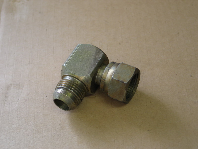
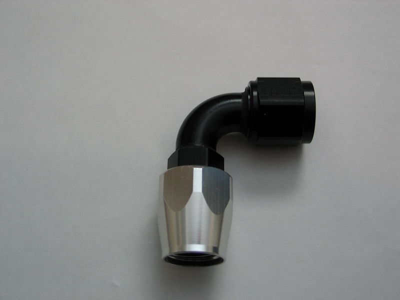
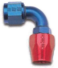
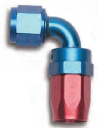
So, in short, the job of plumbing a car consists of selecting the right combination of tubing, hose, hose-end, and adapters to connect together all of the ports of the various components between which we need to transfer fluid. Here’s how we go about doing just that. Basic PrinciplesSo what exactly distinguishes a quality, reliable, leak-free, high-performance plumbing job from a poor, unreliable, failure-prone one? A quality plumbing system will: Be constructed of high-quality components of known reputation The use of cheap, no-name or generic industrial components invites unpredictable performance and unwanted failure. The demands of offroad motorsports are extreme and unique. Maybe cutting a few corners saves you a few bucks, but more likely it costs you a bunch more eventually. Using components from a manufacturer such as Russell Performance, with a proven track record of producing quality plumbing components that withstand the rigours of high performance automotive use is the easiest and best way to be well on the way to creating a quality plumbing system. Have the fewest joints/unions/connections & therefore fewest potential leak paths as possible Each and every connection in a plumbing system is a potential leak path – a point where the system can leak. Minimizing the number of connections is one of the best ways to reduce the risk of potential leaks. This can be achieved through thoughtful design and layout, as well as by the use of the best fittings available. For example, if you need to route a hose assembly 180° from the component to which it attaches, you could go to the hardware store and use two 90° elbows with a straight nipple between them for a total of three potential leak paths; but the far better way to do it would be to use a quality 180° hose-end, like those available from Russell Performance. Russell manufactures hose-ends in straight, 45°, 90°, 120°, and 180° , allowing you to design a system that is neat, clean, and has minimal potential leak paths.
Be easy to install, inspect, diagnose, and maintain Once again, quality components and thoughtful design & layout are key here. You should design your plumbing so that it can easily be inspected periodically, and use components that are readily available and easy to repair or replace. This is an area where using that Komatsu industrial hose and fitting you scavenged from a piece of heavy equipment may not be the best plan. On the other hand, stainless steel braided hose combined with AN/SAE37° field-attachable hose-ends, especially those that allow for clean routing, minimum hose length, and the minimum number of connections, are ideal for creating a system that is easy to install, inspect and maintain. We shall discuss hose-end types and their advantages in detail shortly. For abusive offroad use, particularly for systems that may be subjected to damage, the use of field-attachable hose-ends is a godsend, allowing a length of hose and spare hose-ends to be carried for easy trailside repairs. Be built of components able to handle the minimum and maximum temperatures and maximum pressures that will be experienced by the system Good hose and fittings will have published temperature and pressure limits that must be matched to the system being designed. It’s not only ineffective but also very unsafe to use hose that is unrated or that has an insufficient pressure or temperature rating to carry hot pressurized oil and other automotive fluids. Be built of components that are chemically compatible with the fluids being carried Not all hose is equal, not by a long shot. There are many different materials that can be used in the construction of hose. Particularly when plumbing fuels and oils you must ensure that the hose you use is chemically compatible with, and designed to carry, the fluids in question. Failure to do so puts not only the plumbing itself at risk, but also the components the plumbing connects since incompatible fluids can dissolve the inside of the hose creating debris that can be carried into the engine or fuel injectors or hydraulic steering components. Be as light as possible For those seeking the ultimate competitive edge in climbing or racing, weight is always an issue. Industrial hose and fittings can be bulky and heavy, whereas specialized racing hose and aluminum fittings are both strong and light weight. Minimize pressure drop, turbulence, and friction-heating of the fluid being carried Without going into excruciating detail on the laws of fluid dynamics, it is nevertheless necessary for me to cover the basics of pressure drop, turbulence, venturi effect, vapour pressure, and cavitation before we can make the best informed decision on component selection and design of our plumbing system. Don’t worry – I’ll keep it simple and summarize with some rules of thumb!
|
|||||||||||||||||||||||||||||||||||||||||||||||||||||||||||||||||||||||||||||||||||||||||||||||||||||||||||||||||||||||||||||||||||||||||||||||||||||||||||||||||||||||||||||||||||||||||||||||||||||||||||||||||||||||||||||||||||||||||||||||||||||||||||||||||||||||||||||||||||||||||||||||||||||||||||||||||||||||||||||||||||||||||||||||||||||||||||||||||||||||||||||||||||||||||||||||||||||||||||||||||||||||||||||||||||||||||||||||||||||||||||||||||||||||||||||||||||||||||||||||||||||||||||||||||||||||||||||||||||||||||||||||||||||||||||||||||||||||||||||||||||||||||||||||||||||||||||||||||||||||||||||||||||||||||||||||||||||||||||||||||||||||||||||||||||||||||||||||||||||||||||||||||||||||||||||||||||||||||||||||||||||||||||||||||||||||||||||||||||||||||||||||||||||||||||||||||||||||||||||||||||||||||||||||||||||||||||||||||||||||||||||||||||||||||||||||||||||||||||||||||||||||||||||||||||||||||||||||||||||||||||||||||||||||||||||||||||||||||||||||||||||||||||||||||||||||||||||||||||||||
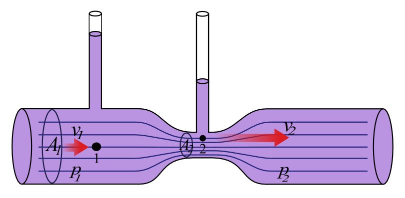 |
A model venturi. At point (2) the speed of the fluid is increased and the pressure decreased, compared to the speed and pressure at point (1). |
||||||||||||||||||||||||||||||||||||||||||||||||||||||||||||||||||||||||||||||||||||||||||||||||||||||||||||||||||||||||||||||||||||||||||||||||||||||||||||||||||||||||||||||||||||||||||||||||||||||||||||||||||||||||||||||||||||||||||||||||||||||||||||||||||||||||||||||||||||||||||||||||||||||||||||||||||||||||||||||||||||||||||||||||||||||||||||||||||||||||||||||||||||||||||||||||||||||||||||||||||||||||||||||||||||||||||||||||||||||||||||||||||||||||||||||||||||||||||||||||||||||||||||||||||||||||||||||||||||||||||||||||||||||||||||||||||||||||||||||||||||||||||||||||||||||||||||||||||||||||||||||||||||||||||||||||||||||||||||||||||||||||||||||||||||||||||||||||||||||||||||||||||||||||||||||||||||||||||||||||||||||||||||||||||||||||||||||||||||||||||||||||||||||||||||||||||||||||||||||||||||||||||||||||||||||||||||||||||||||||||||||||||||||||||||||||||||||||||||||||||||||||||||||||||||||||||||||||||||||||||||||||||||||||||||||||||||||||||||||||||||||||||||||||||||||||||||||||||||||
In summary, if our goal is a quality, reliable, leak-free, high-performance plumbing job - when selecting a product, the total system design must be considered to ensure safe, trouble-free performance. Function, material compatibility, adequate ratings, proper installation, operation, and maintenance are the responsibilities of the system designer and user. We will explore how shortly, but first a word about safety is in order. Plumbing SafetyIf plumbing itself is often overlooked – plumbing safety is something that is rarely considered. This is a gross and dangerous error. Plumbing safety needs to be a serious concern to all of us. Many of the builds or installs that I see contain at least some seriously dangerous plumbing practices - they should be a source of great concern to those involved – here’s why: Automotive plumbing is used to convey hazardous chemicals, steam, hot liquids and high-pressure oil which, if released accidentally, can cause serious bodily injury including burns, pressure wounds or chemical exposure . Selection of the proper hose and fittings for the application is essential for the proper operation and safe use of the system. Inadequate attention to the selection of components or to the design and installation of the plumbing system can result in serious personal injury or equipment damage from:
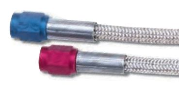
All About Hose & TubingA hose is not a hose. Obviously the hose or tube used in any particular plumbing system plays a huge role in whether the system achieves the requirements of a quality, reliable, leak-free, high-performance plumbing system. Fortunately, hose tech is fairly simple. The job of selecting the right hose consists of matching the specs of the hose in consideration with the job to be done. That, combined with purchasing from a reputable source, will have you well on the way. The important specifications of a hose are: Pressure Rating: Obviously, the hose must be rated to safely carry fluid at the pressure intended. Be extremely wary of hose sold without a pressure rating - even for use in low-pressure applications. As we have discussed, all manner of injury and damage can occur when a hose fails under pressure. In addition, this is unlikely to be beneficial to the motor, transmission, or other component to which the plumbing is attached. Temperature Rating: Both minimum and maximum operating temperatures published for the hose are important. If you drive or even store the car in a cold climate, cold-weather performance of the plumbing hose is crucial. All plumbing, regardless of climate, can be subjected to fluid at extremely high temperatures. Make sure to match the hose used with the maximum temperature that will be seen by the system in question. Be certain that fluid and ambient temperatures, both steady and transient, do not exceed the limitations of the hose. Temperatures below and above the recommended limit can degrade hose to a point where a failure may occur and release fluid. Properly insulate and protect the hose assembly when routing near hot objects (e.g. manifolds). Do not use any hose in any application where failure of the hose could result in the conveyed fluids (or vapours or mist from the conveyed fluids) contacting any open flame, hot manifold, or other potential fire ignition source that could cause burning or explosion of the conveyed fluids or vapours. Abrasion Resistance: Although there isn't a specification or measurement given, a hose's abrasion resistance is nevertheless a critical indicator of its suitability for any given installation. Abrasion is probably responsible for 80 or 90% of hose failures and subsequent plumbing system failures. Good and proper installation procedures, as detailed later in the article, can go a long way, but starting with the right hose for the job is key to success. For this reason, I always recommend a quality stainless-steel braided plumbing hose in off-road and high-performance automotive applications because of the punishing environments of high heat, dirt, and vibration. Vacuum Rating: If the hose in question is to be used as a "suction" line - for example the hose that supplies a power steering pump with fluid from a remote reservoir - it must have a suction or vacuum rating. Vacuum ratings are measured in inches of mercury or in/Hg, and a full suction rating is 28 in/Hg. Hoses used for suction applications must be selected to ensure that the hose will withstand the vacuum and pressure of the system. Improperly selected hose may collapse in suction applications. Any hose suitable for use as a suction hose will have this rating clearly indicated. If it doesn't - it's not the right hose! Chemical Compatibility: Chemical compatibility is about matching the fluid you wish to convey with the material from which the inner core of the hose is made. There are many different materials used in hose construction - known in the industry as "hose elastomers" (an elastomer is just a flexible compound). Common hose elastomers include:
Each has its own strengths and weaknesses, including cost. In addition to chemical compatibility with the fluid carried, the overall hose construction (including the elastomer, any additional braids or layers, and the outermost braid or layer) confers upon the hose its overall properties and capabilities. These in term determine its suitability for a given installation and how it will perform. As with most things in life - you tend to get what you pay for - with the cheapest solution being cheap rubber hose generally acceptable for low pressure and temperatures and highly susceptible to abrasion - with other options available all the way up to CPE or Teflon inner hose with multiple layers of construction including 308 stainless steel inner and outer braids, compatible with all automotive fluids, flexible from -40°C to 350°C, and rated to 1500psi, - like Russell Performance ProRace Hose. The following tables give general properties of different hose elastomers, followed by specific chemical compatibilities for some chemicals common in automotive applications. Be careful using them in isolation, especially the first, in order to make purchasing decisions - as many of the properties listed (like flame resistance and abrasion resistance) can be modified or greatly affected by other materials used in the hose's construction, multiple layers used in the hose, and outer coverings, braids, and sleeves. Table of Elastomer Properties
Table of Chemical Resistance.The following table is an example of a table of chemical resistance. Depending on the hose you plan on using, and the use you have in mind for it, you may need to consult such a table to make sure your design is sound. An alternative can be to purchase a hose, such as Russell ProFlex or Russell ProRace, that is certified compatible with all automotive fluids.
Here are some additional, more extensive, fluid compatibility charts from: Size: Calculating the required size of a hose can be a complicated business, involving calculations of fluid velocity, flow rate, and pressure drop - but fortunately for us it doesn't have to be. This is because many years of experience have taught us some very good rules of thumb for sizing hose in automotive plumbing applications. We'll get to those shortly, but for those who enjoy math and theory or for those who are perhaps working with a truly custom project, we'll cover a little theory first. DO NOT WORRY if you get bogged down in the math and theory that follows. It's not critical to understand - the rules of thumb will serve us well - the theory is provided as optional for true tech nerds only! Remember from our previous discussion that fluid velocity and pressure are related (as velocity, or speed, of the fluid goes up - pressure goes down) and that we wish to keep pressure drop in any plumbing system to a minimum. It stands to reason, then, that we would want to keep fluid velocity in the plumbing from becoming too high. Of course, we don't want it to be zero either, so we actually want to achieve a fluid velocity that is within a reasonable range. Standard industry recommended fluid velocity ranges, in feet per second, are: Suction or intake lines - 2-5 ft/s (e.g. power steering pump supply hose) Low pressure or return lines - 4-15 ft/s (e.g. transmission cooler lines) High pressure lines - 7-18 ft/s (e.g. hydraulic steering power lines) If only there were an equation that relates fluid velocity to hose diameter! Of course, there is:
To use the equation, flow will be taken from the spec of the pump that is moving the fluid. For example, a high-performance oil pump may pump at 10-12 gpm, an EFI fuel pump at 0.7 to 1.5 gpm, a water pump at anywhere from 15-60 gpm, and a power-steering pump at 2-4 gpm. Now, obviously there is quite a range in the acceptable fluid velocity ranges given above, and so this equation can produce quite different values, depending on which end of the velocity range you are using. Knowing which velocity will work for which application is a complicated engineering problem - which brings us back to the rules of thumb, but for those so inclined it is nice to know where the rules come from. For example, if we were to calculate the hose size required for the intake, pressure, and return lines of a hydraulic steering circuit using the above equation, a 4 gpm pump, and both extremes of fluid velocity, we would come up with: Intake: 0.9 - 0.6" diameter (1" to 5/8" or -16 to -10 AN) Return: 0.6 - 0.3" diameter (5/8" to 5/16" or -10 to -05 AN) Pressure: 0.5 - 0.3" (1/2" to 5/16" or -08 to -05 AN) For those that want to do their own calculations or comparisons without having to do a bunch of equations, you can use a chart called a "nomogram" and a straight edge. Click on the picture below to open or download a PDF file of just such a nomogram, complete with instructions and an example problem. Hose Diameter Selection Nomogram
One of the things that accounts for the different velocity recommendations is the other factor that affects the required size for a hose - the length of the hose assembly. The longer the hose, the lower the velocity that is allowable. In addition - the longer the hose, the greater the pressure loss over its length and the greater the potential for friction induced heat generation or excessive fluid turbulence. Once again, calculating specific pressure losses is something of a complex problem, requiring knowledge of flow rate, hose diameter, the specific gravity and viscosity of the fluid in question, the length of hose as well as the number, diameter, and bend radius of all bends in the hose; along with the dimension of any other restrictions to flow such as reduced inside diameters of any fittings. The following diagram (click for full size) gives flow rate versus pressure drop for 100 foot length of different size hoses (hose ID's) for WATER. To read the diagram, first determine the flow rate and select this along the left-hand side. Follow that horizontal line across to the right until it intersects the diagonal line of the hose size of interest. At this intersection, draw a vertical line straight down and read off the pressure drop in PSI. Be aware that the values so given are for a 100' length of hose. To correct for shorter lengths of hose, divide the result by the percentage of 100' that the shorter length is. For example, for a 20' hose, multiply the result by 20% or 0.2, since 20 feet is 20% of 100 feet. Flow Rate vs. Pressure Drop Diagram
This length-corrected result must then be corrected for the actual fluid conveyed if it is not water. This correction takes into account the differences between the specific gravity and viscosity of water versus the fluid in question. To make the correction, DIVIDE the water value by the correction factor for the fluid of interest. Correction factors are shown in the following table:
For interest's sake, I extracted some figures from the diagram, corrected them for a 10' length of hose, corrected them for different fluids, and charted them below for 1/2", 3/4", and 1" hose. The colour-highlighted areas represent typical fluid flow-rates for different systems as shown in the key. For a 20' hose, double the value in the table, for a 30' hose triple it, and so on. Note that I didn't include data for coolant and coolant-sized hoses as even a quick glance at the flow vs pressure drop diagram shows that: even if you had a monster 150 gpm water pump, a small 2" hose, and a long 20' length, pressure drop would only be about 4psi and since most water pumps are closer to 20 gpm and coolant hoses only a couple of feet in length it didn't seem worth extrapolating the data. Pressure Drop in PSI per 10 foot length of hose for various fluids, hose diameters, and flow rates.
Key:
So, what can we learn from all this? First, it's important to note that the data presented is drawn from average data from available sources. It includes many assumptions and possible sources of errors, not the least of which is my extrapolation-by-eyeball from the pressure-drop chart. All told, the data should not be used for precise engineering of custom solutions. Rather, it is offered merely to illustrate the principles that affect selection of hose size regarding pressure drop. For example, notice that, for oil at 10 gpm, a 10" 1/2" hose could result in as much as 24 psi pressure loss, whereas increasing the hose size to 3/4" drops this loss all the way to a mere 3 psi! In short, it is a very long winded way of saying: "Hose inside diameter can have a very big effect on pressure loss, especially at higher flow rates, and this effect is multiplied the longer the hose is" Which is, in itself, a long-winded way of saying: "Use the largest reasonable hose size you can afford, fit, tolerate the weight of, and for which the correct size hose-ends are made." Although it would be great from a pressure-drop perspective, you probably want to avoid plumbing the entire car with 1" hose as it would be prohibitively expensive, needlessly heavy, very hard to install and route nicely, and would result in some god-awful multi-adapter / reducer contraptions to adapt the 1" hose to smaller ports on the car. Which brings us rather nicely to the rules of thumb: Rule of Thumb Automotive Plumbing Hose Sizes
Typical OEM applications make extensive use of -04 and -06 hoses. High performance applications with higher flow and / or longer lines must use larger sizes accordingly. For example, the sizes I run on my rig are as follows:
All About FittingsThere are hundreds if not thousands of different fittings that exist amongst the pneumatics, hydraulics, and plumbing industries. However, there are only a couple of dozen that you are likely to run into in the automotive world and I’m only going to cover those most common in North America. I will not be covering brake fittings, metric, Japanese, European, sizes above 2”, specialized hydraulic, flanges, or quick-disconnect fittings. Regardless of the style, any fitting must do two things:
For all the fittings we shall discuss, the method of holding is via mechanical threads. That leaves the two major criteria that define a fitting as
Threads are identified by their “form” and “series”. Male and female threads must be of the same form and series in order to screw together. Methods of sealing are various, including by way of an O-ring, a soft sealing washer, machined metal-to-metal contact, or by interference fit of the threads themselves. Threads and sealing methods may be combined in many different ways, but there are “most common” configurations – especially when confining our discussion to automotive-type fittings and plumbing. For example, a common method of sealing for hydraulic fittings (and very likely to be found somewhere on off-road rigs with “full hydraulic steering” ) is the ORB or O-ring Boss. This style of fitting is available with UNF (aka SEA or standard or imperial or inch) threads, Metric (ISO 6149) threads, or BSPP (JIS B2351) threads – depending on, amongst other things, what part of the world you are in. However, in North America, the ORB fitting is most often manufactured with UNF threads. As such, I shall list it and refer to it in this article in this configuration. Just be advised that it is possible to combine sealing methods and thread forms in combinations not shown here. In fact, there are several fitting specialty companies, especially those that deal with hydraulics and pneumatics, whose catalogues run to many hundreds of pages. Essentially, for our purposes, and the purposes of this article, we will examine fittings as if certain threads are always combined with certain sealing methods – and this is certainly the case with 99% of those you’re likely to encounter, at least in North America. I just didn’t want to leave you with the impression that it always HAS to be that way. Thread and Sealing Method BasicsThread BasicsSince the threads are a major component of fittings, it behoves us to cover the basics to ensure a complete understanding. |
|||||||||||||||||||||||||||||||||||||||||||||||||||||||||||||||||||||||||||||||||||||||||||||||||||||||||||||||||||||||||||||||||||||||||||||||||||||||||||||||||||||||||||||||||||||||||||||||||||||||||||||||||||||||||||||||||||||||||||||||||||||||||||||||||||||||||||||||||||||||||||||||||||||||||||||||||||||||||||||||||||||||||||||||||||||||||||||||||||||||||||||||||||||||||||||||||||||||||||||||||||||||||||||||||||||||||||||||||||||||||||||||||||||||||||||||||||||||||||||||||||||||||||||||||||||||||||||||||||||||||||||||||||||||||||||||||||||||||||||||||||||||||||||||||||||||||||||||||||||||||||||||||||||||||||||||||||||||||||||||||||||||||||||||||||||||||||||||||||||||||||||||||||||||||||||||||||||||||||||||||||||||||||||||||||||||||||||||||||||||||||||||||||||||||||||||||||||||||||||||||||||||||||||||||||||||||||||||||||||||||||||||||||||||||||||||||||||||||||||||||||||||||||||||||||||||||||||||||||||||||||||||||||||||||||||||||||||||||||||||||||||||||||||||||||||||||||||||||||||||
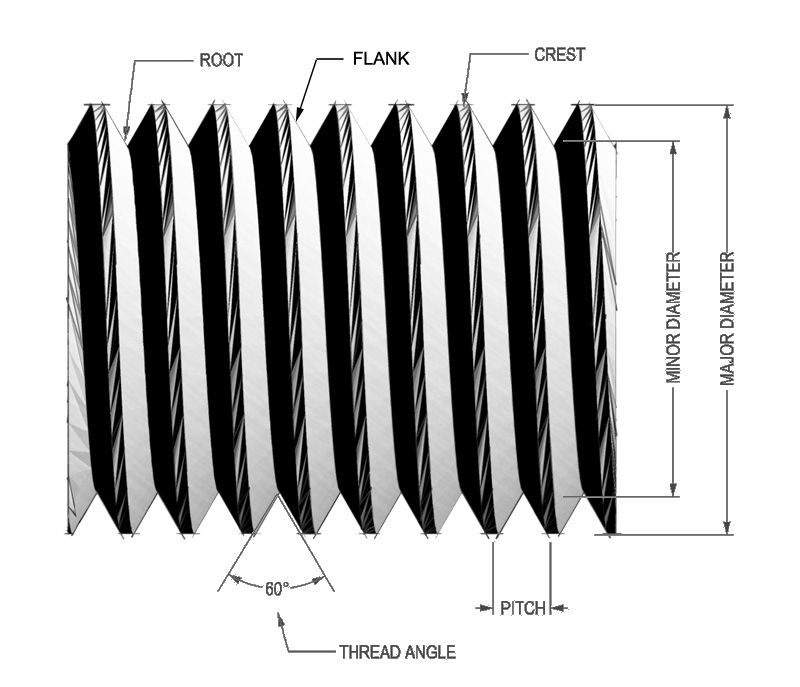 |
The basic parts and most important dimensions of a thread are illustrated in the diagram at left. A male thread is depicted, but the terms apply equally to female threads. The crest of a thread is the tip, the root of the thread is the bottom or valley between threads, and the flank of a thread is the “side” between the crest and root. Thread pitch is the distance from a point on the thread to a corresponding point on the next thread measured parallel to the fitting’s axis. In other words, It is the distance between threads and is often expressed as the number of threads per inch. The OD or major diameter is the largest diameter of a thread (measured across the crests of the thread) The ID or minor diameter is the smallest diameter of a thread (measured across the roots of the thread). The flank angle, also known as the “thread angle”, is the angle formed between two adjacent flanks. The taper angle, for threads that are not parallel, is the angle at which the threads taper. |
||||||||||||||||||||||||||||||||||||||||||||||||||||||||||||||||||||||||||||||||||||||||||||||||||||||||||||||||||||||||||||||||||||||||||||||||||||||||||||||||||||||||||||||||||||||||||||||||||||||||||||||||||||||||||||||||||||||||||||||||||||||||||||||||||||||||||||||||||||||||||||||||||||||||||||||||||||||||||||||||||||||||||||||||||||||||||||||||||||||||||||||||||||||||||||||||||||||||||||||||||||||||||||||||||||||||||||||||||||||||||||||||||||||||||||||||||||||||||||||||||||||||||||||||||||||||||||||||||||||||||||||||||||||||||||||||||||||||||||||||||||||||||||||||||||||||||||||||||||||||||||||||||||||||||||||||||||||||||||||||||||||||||||||||||||||||||||||||||||||||||||||||||||||||||||||||||||||||||||||||||||||||||||||||||||||||||||||||||||||||||||||||||||||||||||||||||||||||||||||||||||||||||||||||||||||||||||||||||||||||||||||||||||||||||||||||||||||||||||||||||||||||||||||||||||||||||||||||||||||||||||||||||||||||||||||||||||||||||||||||||||||||||||||||||||||||||||||||||||||
Not all threads are made the same way. Different types of threads, or “thread forms”, will have different dimensions such as the flank angle used. Obviously it’s important to be able to distinguish between different threads so that we know what can be screwed into what. In order for threads to mate, they must be the same size, thread form and series, and have the same pitch (# of threads per inch). Thread Form The thread form is a the “group” to which particular threads belong based on a published industry standard that sets out the shape, dimensions, and tolerances for the formation of the threads. Examples of thread forms include:
Thread Series Thread Series – often within a thread form, threads are grouped into series, based on their combination of size, pitch, and any taper (if applicable). For example, UNF stands for Unified National Fine and is a thread series within the UN thread form. Other common series include:
Not all threads of a given form fit into a series. For example, a UN thread having ¾” diameter and 18 TPI is neither course thread (UNC series) nor fine thread (UNF series). Odd and special sizes such as these that do not fit into a series, if they are UN form, are referred to as UNS or Unified National Special. Basically, for threads to thread together, they must have matching diameter and pitch (TPI), the “series” is just a convenient way of grouping threads. For example, one could refer to ‘¾” fine thread', or ' ¾” UNF’ instead of specifying ¾”-16 TPI; although it is always best practice to refer to any thread by its specific size and pitch. Threads on Fittings As mentioned, in order to function, fittings must accomplish two things – they must securely attach the components which they join, and they must seal the fluid they carry. Fittings use threads for mechanical attachment, and one of a number of different sealing methods – including using the threads themselves. That is to say, depending on the fitting, it will attach via threads and either seal also via the threads or seal by some other method. In other words, there are two broad groups of thread found on fittings: those that attach AND seal, and those that just attach. Threads that both attach and seal are tapered threads, and those that simply attach are parallel or “straight” threads. There are three thread forms of interest to us in automotive plumbing – American National Pipe threads (NP), British Standard Pipe threads (BS), and Unified National (UN) threads. NP and BS threads have both a tapered and parallel thread variant, whereas all UN threads are parallel. Tapered threads seal by means of an interference fit between the male and female threads. That is, as the threads are screwed together, metal deformation occurs between the threads and a metal-to-metal seal is achieved. However, tapered threads often use some supplement to this seal in the form of a sealing compound between the threads. The most commonly used is Teflon “plumber’s tape”. The purpose of the tape is actually two-fold. First, it provides some “lubrication” between the male and female threads, reducing the amount of thread-galling that occurs as the threads are screwed together. This is particularly important if the threads are ever to be disassembled and re-used. |
|||||||||||||||||||||||||||||||||||||||||||||||||||||||||||||||||||||||||||||||||||||||||||||||||||||||||||||||||||||||||||||||||||||||||||||||||||||||||||||||||||||||||||||||||||||||||||||||||||||||||||||||||||||||||||||||||||||||||||||||||||||||||||||||||||||||||||||||||||||||||||||||||||||||||||||||||||||||||||||||||||||||||||||||||||||||||||||||||||||||||||||||||||||||||||||||||||||||||||||||||||||||||||||||||||||||||||||||||||||||||||||||||||||||||||||||||||||||||||||||||||||||||||||||||||||||||||||||||||||||||||||||||||||||||||||||||||||||||||||||||||||||||||||||||||||||||||||||||||||||||||||||||||||||||||||||||||||||||||||||||||||||||||||||||||||||||||||||||||||||||||||||||||||||||||||||||||||||||||||||||||||||||||||||||||||||||||||||||||||||||||||||||||||||||||||||||||||||||||||||||||||||||||||||||||||||||||||||||||||||||||||||||||||||||||||||||||||||||||||||||||||||||||||||||||||||||||||||||||||||||||||||||||||||||||||||||||||||||||||||||||||||||||||||||||||||||||||||||||||||
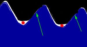 |
Secondly, in the case of some tapered threads, the seal is made when the flanks make contact (green arrows). In this case, there is a gap between the crest and roots of the male and female threads. This gap leaves a spiral leak path in the joint (red) which must be sealed by the use of a sealing compound such as Teflon tape. American NPT threads suffer from this problem. | ||||||||||||||||||||||||||||||||||||||||||||||||||||||||||||||||||||||||||||||||||||||||||||||||||||||||||||||||||||||||||||||||||||||||||||||||||||||||||||||||||||||||||||||||||||||||||||||||||||||||||||||||||||||||||||||||||||||||||||||||||||||||||||||||||||||||||||||||||||||||||||||||||||||||||||||||||||||||||||||||||||||||||||||||||||||||||||||||||||||||||||||||||||||||||||||||||||||||||||||||||||||||||||||||||||||||||||||||||||||||||||||||||||||||||||||||||||||||||||||||||||||||||||||||||||||||||||||||||||||||||||||||||||||||||||||||||||||||||||||||||||||||||||||||||||||||||||||||||||||||||||||||||||||||||||||||||||||||||||||||||||||||||||||||||||||||||||||||||||||||||||||||||||||||||||||||||||||||||||||||||||||||||||||||||||||||||||||||||||||||||||||||||||||||||||||||||||||||||||||||||||||||||||||||||||||||||||||||||||||||||||||||||||||||||||||||||||||||||||||||||||||||||||||||||||||||||||||||||||||||||||||||||||||||||||||||||||||||||||||||||||||||||||||||||||||||||||||||||||||
Normally, 2 to 3 turns of Teflon tape wrapped around the male thread before assembly is adequate. Liquid Teflon-based sealants are also used successfully to ensure a pressure tight seal. It is always important to use care when applying sealants to avoid introducing the sealant material into the system flow path. This is particularly true in critical hydraulic applications such as steering and braking systems where even a tiny piece of debris in the plumbing can block a crucial orifice or port, causing system failure. NP Threads NP threads are manufactured to various ANSI/ASME and SAE standards. There are both tapered and straight versions, however all NP threads have a 60° flank angle and have thread pitch measured in threads per inch. There are also a number of variants of NP threads. The two most important to us are: NPT – American National Standard Taper Pipe Thread (ANSI B1.20.1). NPT threads are by far the most common NP thread. They are tapered interference fit threads where the crests and roots of the threads are truncated (cut off) so that the flanks come into contact to form the seal. This results in a spiral leak path at the crests and roots and therefore a sealant compound or Teflon tape must be used for a leak-free seal. The threads have a taper of 1° 47' 24" or 1.7899°, meaning the thread tapers ¾” for every foot in length or 1 in 16. NPT threads have a 60° thread angle and the thread pitch is measured in threads per inch (TPI). Each thread size has a defined number of threads per inch. Both the TPI and OD of the thread are required for positive identification of thread size because more than one size has the same TPI. Pipe thread sizes are nominal only – meaning they are a name only. The “size” does not refer to any physical dimension – not the thread size, fitting ID nor fitting OD. For example, a male ¾” NPT fitting has a thread OD of 1.05 inches. To identify an NPT fitting by thread size the thread OD and pitch must be measured and the results compared to a chart like those given later in this article. However, as a rule of thumb, for NP sizes up to 1-1/4”, you can measure the diameter of the threads and subtract 1/4" to get the nominal size. For example, subtract 1/4" from a 1" thread O.D. to obtain the nominal pipe size of 3/4". You may also see the abbreviation NPT defined as:
In addition, NPT threads may also be referred to as:
NPTF - Dryseal USA (American) Standard Taper Pipe Thread (ANSI B1.20.3) aka American National Standard Taper Pipe Thread - Fuel Because of the spiral leak path problem with NPT threads, some years ago the Society of Automotive Engineers in cooperation with industry set up a standard for improvement in pipe threads. This improvement is known as the Dryseal Pipe Thread. With this thread design, there are controls on the crests and roots of both the male and the female threads to ensure the crest crushes into the root of the mating thread. The interference fit between the crest of one thread and the root of the other, along with the thread flanks matching, seals against spiral leakage. Apart from this design improvement NPTF threads share remaining characteristics with NPT threads and will appear identical to the naked eye. If both male and female threads are NPTF, strictly speaking thread sealant is not required to form a leak-free seal on first assembly (although it usually is on subsequent assemblies). This can be an advantage in applications where there is a risk of contaminating the fluid with extraneous thread sealant or bits of Teflon tape. However, in any tapered interference-fit thread, if possible, it is still a good idea to use some sealant to lubricate the threads and minimize galling. Although not ideal, NPT and NPTF threads can be combined, but sealant will be required. There are also a large number of other specialized NP thread variants in use - although rarely in the automotive industry. I list them here only so you may recognize what they are if you should come across them.
British Standard (BS) Pipe Threads BSP threads are of the Whitworth thread form. This thread form differs from both NP and UN threads by its use of a 55° flank angle (versus the 60° flank angle used on the NP & UN threads). Because of this difference, the thread forms are NOT interchangeable. The Whitworth thread form is common for pipe fittings in countries that otherwise use metric threads. BSP threads are rounded equally at the crests and roots. There are two forms of British Standard Pipe Threads in use today - BSPT (British Standard Pipe Tapered) and BSPP (British Standard Pipe Parallel). BSPT threads are a tapered interference fit, similar to NPTF threads, and also have a taper of 1° 47' 24" or 1.7899°, meaning the thread tapers ¾” for every foot in length or 1 in 16. BSPT threads are also referred to as “R series threads”, the R coming from the German word “Rohr”, for pipe. As such, frequently BSPP threads are designated by the letter R for external (male) taper threads or the letters Rc for internal (female) taper threads, followed by the nominal pipe size in inches, such as: R-1/2 or Although you may also see the designation include the thread pitch in TPI, as in: R-1/2-14 BSPT threads may also be referred to as:
And / or be designated by the symbology:
BSPP threads are parallel threads and therefore require a separate sealing system apart from the threads. The male BSPP fitting has a 30° flare that mates with a matching female BSPP 30° cone, although frequently an additional sealing ring or washer is used to achieve a pressure-tight seal. BSPP threads are also referred to as “G series threads”, the G coming from the German word “Gaz”, as the threads were originally designed for gas pipe. As such, frequently BSPT threads are designated by just the letter G, followed by the nominal pipe size in inches, such as: G-1/2, or sometimes Although you may also see the designation include the thread pitch in TPI, as in: G-3/8–19 BSPP threads may also be referred to as:
And / or be designated by the symbology:
A BSPT male can be screwed into a BSPP female, but not the other way around. British Pipe thread sizes There are 16 thread sizes defined by the standards, ranging from 1/16” to 6”. The size number was originally based on the inner diameter measured in inches of a steel tube for which the thread was intended, but is simply a nominal size number in the modern version of the standard. UN Threads All UN threads used on plumbing fittings are parallel threads and only serve the function of attaching the fitting. Sealing is achieved by some other means, such as with an O-ring or machined surface. UN threads have a 60° flank angle and are grouped into thread series based on pitch. The following UN thread series are common in automotive plumbing fittings:
Thread Class UN threads are also grouped by “thread class”. Thread classes are based on the amount of tolerance and allowance permitted in the manufacture of the threads. The higher the class, the tighter the tolerance. Classes are assigned a numeral, followed by the letter A for external threads or the letter B for internal threads, as follows: Class 1A/1B – Designed for ordnance and other special uses, class 1 threads have large tolerances & allowances to permit quick and easy assembly, even with dirty or slightly damaged threads. Class 2A/2B – Designed for most general commercial and industrial uses including nuts, bolts, and fittings. Class 2 threads are by far the most common and 99% of the threads you encounter are likely to be class 2. Class 3A/3B – Designed for use where closer tolerance than afforded by class 2 threads is desired. Class 3 threads are such that the upper end of the male tolerance and the lower end of the female tolerance would produce threads with no clearance for assembly. Class 3 threads are uncommon and can be difficult to do up, especially if not perfectly clean. Bottom line – most UN threads you will encounter are class 2. UN Thread Sealing Methods The various sealing methods used with UN thread fittings include:
The sealing method for each of the most common automotive plumbing fittings are detailed below in the sections on the individual fitting styles. Drilling & TappingWhile this article is not intended to be a technical treatise on the fine art of drilling for and tapping threads, information is provided should you need to drill and tap a hole for a fitting for some reason. Of course, because all straight threads found on fasteners require some sort of sealing method other than the threads, unless you are capable of machining the appropriate surface or chamfer for an O-ring or soft sealing washer or the like, most home-brew tapping for plumbing fittings is probably best confined to the tapered thread forms (NPT / NPTF / BSPT). That said, if it is a low pressure non-critical function you have in mind (such as a vent port for an axle or transmission), and you don’t want to use a tapered thread form (and who can blame you!) you can use the information provided to, for example, drill and tap an ORB fitting hole in an axle housing and then use an ORB to AN / SAE 37° fitting in the hole allowing you to run a hose with AN fittings on it. The advantage to this over tapered threads is that you are likely to already have many more UN taps than NP taps. Of course, if you’re stuck, you could also always use the information provided to decide what chance of success you might have of ramming two mismatched fittings together…not that I would EVER do that ;-) The recommendations given in the tables in this article for min and max hole sizes and the accompanying drills to be used for drilling holes to be tapped are based on the following assumptions, guidelines, and rules-of-thumb:
Once the hole size for the tapping has been calculated by considering the thread depth, depth of engagement, thread class, the material to be tapped, and the type of tap to be used – you still need to actually drill the hole; and as such are limited by the size of drills available to you. These variables are the reason that a range of hole sizes and accompanying drill sizes are given in the tables later in the article (these hole-size and drill-size listings are included with the data tables for each type of fitting). Where two drill sizes are given, I normally use the smaller size:
Otherwise I would use the larger of the two drill sizes given. Plumbing Sizing Sizing hose, tube, and fittings can be a little confusing for the beginner. This is because the nominal size rarely, if ever, corresponds to an actual measurable dimension. This seems counterintuitive at first, but actually simplifies things once you understand the systems. Nominal sizes refer to the named size – i.e. the size that would be printed on the package or stamped on the fitting. The most important thing to understand is that these nominal sizes are a close approximation to the tube or bore size of the plumbing component in question and NOT the thread size. For example, a ½” fitting, whether it be NPT, AN/SAE 37, SAE 45° flare, or ORS (O-ring Face Seal) has an ID or bore of “approximately” ½”. The actual ID or bore will be something less than ½”, but it will be close. Depending on the style of fitting, the THREAD size of a ½” fitting may range from ¾” to 13/16”. Actual thread sizes can be measured to aid in the identification of fittings, as will be explained shortly, but again the important point here is that a ½” fitting will not have any dimension that is actually ½”. The same is true for hose and tube. A ½” hose will have an OD greater than ½” and an ID somewhat smaller than ½”. For example, ½” Russell performance Proflex hose has an ID of 7/16” and an OD of 5/8”. Other brands of ½” hose may well have different precise dimensions, depending on the construction method. The same is true for different brands or styles of fittings – they may well have slightly different bore diameters. Imagine the headache if you had to measure, verify, and match all those different dimensions in order to design and construct a plumbing system! This is where the advantage of a “nominal” system comes into play. Regardless of the manufacturer in questions, as long as the hose and fittings in question are designed to be used together, it doesn’t much matter what the precise dimensions are – a ½” hose is a ½” hose and would be used with a ½” fitting – be that fitting AN, NPT, or SAE 45° flare. AN or Dash Sizing The AN (Army-Navy) standard was established many years ago by the U.S. military to set a common system for designating the size of hose and fittings. The system is based on the nominal outside diameter (O.D.) of the ridged metal tube that is compatible with each size of fitting – the same as “inch sizing” that we have just discussed. The only difference is, AN sizes always refer to the size in sixteenths of an inch, and are expressed as a dash, followed by a two digit number. For example, AN size -08 translates to 8 sixteenths of an inch or ½”. The system is so convenient and simple to use that it is often used with hose and fittings that are not AN standard, and as such is sometimes referred to as “dash sizing” because of the dash in the designation. To convert from dash sizing to inch sizing, simply place the dash number over a denominator of 16 and reduce the fraction as required. The following table shows the conversion for most common sizes.
The most commonly used size for hose and fittings in automotive plumbing are indicated in the table in bold text. Let’s have a look at some universal fitting tech, and then finally get into the details of each of the most common types of fittings in automotive plumbing. Fitting Construction - aluminum vs steel vs brass Fittings are commonly constructed of steel, brass, or aluminum. |
|||||||||||||||||||||||||||||||||||||||||||||||||||||||||||||||||||||||||||||||||||||||||||||||||||||||||||||||||||||||||||||||||||||||||||||||||||||||||||||||||||||||||||||||||||||||||||||||||||||||||||||||||||||||||||||||||||||||||||||||||||||||||||||||||||||||||||||||||||||||||||||||||||||||||||||||||||||||||||||||||||||||||||||||||||||||||||||||||||||||||||||||||||||||||||||||||||||||||||||||||||||||||||||||||||||||||||||||||||||||||||||||||||||||||||||||||||||||||||||||||||||||||||||||||||||||||||||||||||||||||||||||||||||||||||||||||||||||||||||||||||||||||||||||||||||||||||||||||||||||||||||||||||||||||||||||||||||||||||||||||||||||||||||||||||||||||||||||||||||||||||||||||||||||||||||||||||||||||||||||||||||||||||||||||||||||||||||||||||||||||||||||||||||||||||||||||||||||||||||||||||||||||||||||||||||||||||||||||||||||||||||||||||||||||||||||||||||||||||||||||||||||||||||||||||||||||||||||||||||||||||||||||||||||||||||||||||||||||||||||||||||||||||||||||||||||||||||||||||||||
 |
Steel – strong, hard, heavy, susceptible to corrosion if not plated. As steel is much harder than brass or aluminum, use of steel tapered threads joined to any other metal can lead to problems like port cracking. For example, I wouldn’t thread a steel male tapered pipe thread into an aluminum female port for risk of cracking the aluminum. | ||||||||||||||||||||||||||||||||||||||||||||||||||||||||||||||||||||||||||||||||||||||||||||||||||||||||||||||||||||||||||||||||||||||||||||||||||||||||||||||||||||||||||||||||||||||||||||||||||||||||||||||||||||||||||||||||||||||||||||||||||||||||||||||||||||||||||||||||||||||||||||||||||||||||||||||||||||||||||||||||||||||||||||||||||||||||||||||||||||||||||||||||||||||||||||||||||||||||||||||||||||||||||||||||||||||||||||||||||||||||||||||||||||||||||||||||||||||||||||||||||||||||||||||||||||||||||||||||||||||||||||||||||||||||||||||||||||||||||||||||||||||||||||||||||||||||||||||||||||||||||||||||||||||||||||||||||||||||||||||||||||||||||||||||||||||||||||||||||||||||||||||||||||||||||||||||||||||||||||||||||||||||||||||||||||||||||||||||||||||||||||||||||||||||||||||||||||||||||||||||||||||||||||||||||||||||||||||||||||||||||||||||||||||||||||||||||||||||||||||||||||||||||||||||||||||||||||||||||||||||||||||||||||||||||||||||||||||||||||||||||||||||||||||||||||||||||||||||||||||
 |
Brass – Strong, very heavy, softer than steel, tapered threads tend to gall and deform easily. Mostly used in industrial / hydraulic applications. | ||||||||||||||||||||||||||||||||||||||||||||||||||||||||||||||||||||||||||||||||||||||||||||||||||||||||||||||||||||||||||||||||||||||||||||||||||||||||||||||||||||||||||||||||||||||||||||||||||||||||||||||||||||||||||||||||||||||||||||||||||||||||||||||||||||||||||||||||||||||||||||||||||||||||||||||||||||||||||||||||||||||||||||||||||||||||||||||||||||||||||||||||||||||||||||||||||||||||||||||||||||||||||||||||||||||||||||||||||||||||||||||||||||||||||||||||||||||||||||||||||||||||||||||||||||||||||||||||||||||||||||||||||||||||||||||||||||||||||||||||||||||||||||||||||||||||||||||||||||||||||||||||||||||||||||||||||||||||||||||||||||||||||||||||||||||||||||||||||||||||||||||||||||||||||||||||||||||||||||||||||||||||||||||||||||||||||||||||||||||||||||||||||||||||||||||||||||||||||||||||||||||||||||||||||||||||||||||||||||||||||||||||||||||||||||||||||||||||||||||||||||||||||||||||||||||||||||||||||||||||||||||||||||||||||||||||||||||||||||||||||||||||||||||||||||||||||||||||||||||
 |
Aluminum – strong, corrosion resistant, lightweight, good compromise between thread strength and softness giving low risk of assembly damage and good ability to be disassembled and reassembled. | ||||||||||||||||||||||||||||||||||||||||||||||||||||||||||||||||||||||||||||||||||||||||||||||||||||||||||||||||||||||||||||||||||||||||||||||||||||||||||||||||||||||||||||||||||||||||||||||||||||||||||||||||||||||||||||||||||||||||||||||||||||||||||||||||||||||||||||||||||||||||||||||||||||||||||||||||||||||||||||||||||||||||||||||||||||||||||||||||||||||||||||||||||||||||||||||||||||||||||||||||||||||||||||||||||||||||||||||||||||||||||||||||||||||||||||||||||||||||||||||||||||||||||||||||||||||||||||||||||||||||||||||||||||||||||||||||||||||||||||||||||||||||||||||||||||||||||||||||||||||||||||||||||||||||||||||||||||||||||||||||||||||||||||||||||||||||||||||||||||||||||||||||||||||||||||||||||||||||||||||||||||||||||||||||||||||||||||||||||||||||||||||||||||||||||||||||||||||||||||||||||||||||||||||||||||||||||||||||||||||||||||||||||||||||||||||||||||||||||||||||||||||||||||||||||||||||||||||||||||||||||||||||||||||||||||||||||||||||||||||||||||||||||||||||||||||||||||||||||||||
Crimp vs field attachable vs hose barb (Twist-Lok) Hose-ends can be attached to hose by one of three methods |
|||||||||||||||||||||||||||||||||||||||||||||||||||||||||||||||||||||||||||||||||||||||||||||||||||||||||||||||||||||||||||||||||||||||||||||||||||||||||||||||||||||||||||||||||||||||||||||||||||||||||||||||||||||||||||||||||||||||||||||||||||||||||||||||||||||||||||||||||||||||||||||||||||||||||||||||||||||||||||||||||||||||||||||||||||||||||||||||||||||||||||||||||||||||||||||||||||||||||||||||||||||||||||||||||||||||||||||||||||||||||||||||||||||||||||||||||||||||||||||||||||||||||||||||||||||||||||||||||||||||||||||||||||||||||||||||||||||||||||||||||||||||||||||||||||||||||||||||||||||||||||||||||||||||||||||||||||||||||||||||||||||||||||||||||||||||||||||||||||||||||||||||||||||||||||||||||||||||||||||||||||||||||||||||||||||||||||||||||||||||||||||||||||||||||||||||||||||||||||||||||||||||||||||||||||||||||||||||||||||||||||||||||||||||||||||||||||||||||||||||||||||||||||||||||||||||||||||||||||||||||||||||||||||||||||||||||||||||||||||||||||||||||||||||||||||||||||||||||||||||
 |
Hose Barb – for use only with low pressure hose. Easy to make custom-length hose assemblies at home. Newer, high-quality systems like Russell’s Twist-Lok system do not require any hose clamps. Because of the tight one-way union between barb and hose, removal of hose-end from hose often requires cutting the hose, shortening the length of the hose and making reassembly problematic. | ||||||||||||||||||||||||||||||||||||||||||||||||||||||||||||||||||||||||||||||||||||||||||||||||||||||||||||||||||||||||||||||||||||||||||||||||||||||||||||||||||||||||||||||||||||||||||||||||||||||||||||||||||||||||||||||||||||||||||||||||||||||||||||||||||||||||||||||||||||||||||||||||||||||||||||||||||||||||||||||||||||||||||||||||||||||||||||||||||||||||||||||||||||||||||||||||||||||||||||||||||||||||||||||||||||||||||||||||||||||||||||||||||||||||||||||||||||||||||||||||||||||||||||||||||||||||||||||||||||||||||||||||||||||||||||||||||||||||||||||||||||||||||||||||||||||||||||||||||||||||||||||||||||||||||||||||||||||||||||||||||||||||||||||||||||||||||||||||||||||||||||||||||||||||||||||||||||||||||||||||||||||||||||||||||||||||||||||||||||||||||||||||||||||||||||||||||||||||||||||||||||||||||||||||||||||||||||||||||||||||||||||||||||||||||||||||||||||||||||||||||||||||||||||||||||||||||||||||||||||||||||||||||||||||||||||||||||||||||||||||||||||||||||||||||||||||||||||||||||||
 |
Crimp – crimped hose-ends, if done using the proper equipment by trained personnel, offer very secure and reliable connections. The disadvantages are that you must know the exact length of the required hose assembly before ordering, they cannot be easily made at home without expensive equipment, and they are not field serviceable – if a hose-end fails the entire hose assembly must be replaced. | ||||||||||||||||||||||||||||||||||||||||||||||||||||||||||||||||||||||||||||||||||||||||||||||||||||||||||||||||||||||||||||||||||||||||||||||||||||||||||||||||||||||||||||||||||||||||||||||||||||||||||||||||||||||||||||||||||||||||||||||||||||||||||||||||||||||||||||||||||||||||||||||||||||||||||||||||||||||||||||||||||||||||||||||||||||||||||||||||||||||||||||||||||||||||||||||||||||||||||||||||||||||||||||||||||||||||||||||||||||||||||||||||||||||||||||||||||||||||||||||||||||||||||||||||||||||||||||||||||||||||||||||||||||||||||||||||||||||||||||||||||||||||||||||||||||||||||||||||||||||||||||||||||||||||||||||||||||||||||||||||||||||||||||||||||||||||||||||||||||||||||||||||||||||||||||||||||||||||||||||||||||||||||||||||||||||||||||||||||||||||||||||||||||||||||||||||||||||||||||||||||||||||||||||||||||||||||||||||||||||||||||||||||||||||||||||||||||||||||||||||||||||||||||||||||||||||||||||||||||||||||||||||||||||||||||||||||||||||||||||||||||||||||||||||||||||||||||||||||||||
|
Field Attachable – also known as "socket hose-ends" or "reusable hose-ends", this style of hose-end is easily attached to the hose at home. The advantages are:
|
||||||||||||||||||||||||||||||||||||||||||||||||||||||||||||||||||||||||||||||||||||||||||||||||||||||||||||||||||||||||||||||||||||||||||||||||||||||||||||||||||||||||||||||||||||||||||||||||||||||||||||||||||||||||||||||||||||||||||||||||||||||||||||||||||||||||||||||||||||||||||||||||||||||||||||||||||||||||||||||||||||||||||||||||||||||||||||||||||||||||||||||||||||||||||||||||||||||||||||||||||||||||||||||||||||||||||||||||||||||||||||||||||||||||||||||||||||||||||||||||||||||||||||||||||||||||||||||||||||||||||||||||||||||||||||||||||||||||||||||||||||||||||||||||||||||||||||||||||||||||||||||||||||||||||||||||||||||||||||||||||||||||||||||||||||||||||||||||||||||||||||||||||||||||||||||||||||||||||||||||||||||||||||||||||||||||||||||||||||||||||||||||||||||||||||||||||||||||||||||||||||||||||||||||||||||||||||||||||||||||||||||||||||||||||||||||||||||||||||||||||||||||||||||||||||||||||||||||||||||||||||||||||||||||||||||||||||||||||||||||||||||||||||||||||||||||||||||||||||||
Swivel or not? Once you have decided on a hose-end style, material, and hose attachment style, the only choice remaining is whether or not to use a swivel hose-end or not. For example, suppose you have chosen to use an AN/SAE 37° hose-end style in field-attachable aluminum. This type of hose-end is available in both regular and swivel styles. Both styles can be rotated at the hose-end to adapter point to allow the hose to be oriented as required on installation simply by holding the hose in place as the nut is tightened. However, a swivel hose-end is also able to rotate freely at the hose-end to hose joint after installation. This means the hose can be rotated (or is free to swivel along its length - around its longitudinal axis) after assembly. The benefits are that swivel hose-ends are more easy to install since the hose can swivel after the hose-ends are tightened, which can considerably ease routing the hose. However, the most important advantage is that, since it is able to rotate or swivel in service, a swivel hose-end can prevent unnecessary twisting loads on the hose assembly during use. This can be very important since twisting forces can lead to significantly reduced hose life or hose failure. The disadvantage to swivel hose-ends is the increased cost and the addition of an additional potential failure point in the swivel mechanism. The decision on which to use is best left to particular installation conditions in consideration of the mechanical loads on the hose assembly in service. |
|||||||||||||||||||||||||||||||||||||||||||||||||||||||||||||||||||||||||||||||||||||||||||||||||||||||||||||||||||||||||||||||||||||||||||||||||||||||||||||||||||||||||||||||||||||||||||||||||||||||||||||||||||||||||||||||||||||||||||||||||||||||||||||||||||||||||||||||||||||||||||||||||||||||||||||||||||||||||||||||||||||||||||||||||||||||||||||||||||||||||||||||||||||||||||||||||||||||||||||||||||||||||||||||||||||||||||||||||||||||||||||||||||||||||||||||||||||||||||||||||||||||||||||||||||||||||||||||||||||||||||||||||||||||||||||||||||||||||||||||||||||||||||||||||||||||||||||||||||||||||||||||||||||||||||||||||||||||||||||||||||||||||||||||||||||||||||||||||||||||||||||||||||||||||||||||||||||||||||||||||||||||||||||||||||||||||||||||||||||||||||||||||||||||||||||||||||||||||||||||||||||||||||||||||||||||||||||||||||||||||||||||||||||||||||||||||||||||||||||||||||||||||||||||||||||||||||||||||||||||||||||||||||||||||||||||||||||||||||||||||||||||||||||||||||||||||||||||||||||||
 |
Standard hose-end fitting. | ||||||||||||||||||||||||||||||||||||||||||||||||||||||||||||||||||||||||||||||||||||||||||||||||||||||||||||||||||||||||||||||||||||||||||||||||||||||||||||||||||||||||||||||||||||||||||||||||||||||||||||||||||||||||||||||||||||||||||||||||||||||||||||||||||||||||||||||||||||||||||||||||||||||||||||||||||||||||||||||||||||||||||||||||||||||||||||||||||||||||||||||||||||||||||||||||||||||||||||||||||||||||||||||||||||||||||||||||||||||||||||||||||||||||||||||||||||||||||||||||||||||||||||||||||||||||||||||||||||||||||||||||||||||||||||||||||||||||||||||||||||||||||||||||||||||||||||||||||||||||||||||||||||||||||||||||||||||||||||||||||||||||||||||||||||||||||||||||||||||||||||||||||||||||||||||||||||||||||||||||||||||||||||||||||||||||||||||||||||||||||||||||||||||||||||||||||||||||||||||||||||||||||||||||||||||||||||||||||||||||||||||||||||||||||||||||||||||||||||||||||||||||||||||||||||||||||||||||||||||||||||||||||||||||||||||||||||||||||||||||||||||||||||||||||||||||||||||||||||||
 |
360°swivel hose-end fitting. Note the swivel assembly above the red socket. |
||||||||||||||||||||||||||||||||||||||||||||||||||||||||||||||||||||||||||||||||||||||||||||||||||||||||||||||||||||||||||||||||||||||||||||||||||||||||||||||||||||||||||||||||||||||||||||||||||||||||||||||||||||||||||||||||||||||||||||||||||||||||||||||||||||||||||||||||||||||||||||||||||||||||||||||||||||||||||||||||||||||||||||||||||||||||||||||||||||||||||||||||||||||||||||||||||||||||||||||||||||||||||||||||||||||||||||||||||||||||||||||||||||||||||||||||||||||||||||||||||||||||||||||||||||||||||||||||||||||||||||||||||||||||||||||||||||||||||||||||||||||||||||||||||||||||||||||||||||||||||||||||||||||||||||||||||||||||||||||||||||||||||||||||||||||||||||||||||||||||||||||||||||||||||||||||||||||||||||||||||||||||||||||||||||||||||||||||||||||||||||||||||||||||||||||||||||||||||||||||||||||||||||||||||||||||||||||||||||||||||||||||||||||||||||||||||||||||||||||||||||||||||||||||||||||||||||||||||||||||||||||||||||||||||||||||||||||||||||||||||||||||||||||||||||||||||||||||||||||
Fitting / Thread ExaminationIn this section I will detail each of the most common style of fittings found in automotive plumbing. In the diagrams, I have tried to indicate the actual sealing surfaces in red. To the uninitiated, some of the naming conventions can be confusing. For example - what is the difference between an SAE 45° Flare and an SAE 45° Inverted Flare - and how can I remember them and identify them later by sight? In this regard I find it helpful to think in terms of the female (internal thread) fitting or seat. That is, if you look at SAE 45° Flare fittings, the female seat is either flared tube, or a machined seat the same shape as flared tube - that is, the female sealing surface is concave or "flared" in shape. On the other hand, if you look at SAE 45° Inverted Flare fittings you find that the female (internal thread) sealing surface or seat is a convex, conical shape - i.e. it is the opposite of a flare - an "inverted flare." In other words - "flare" fittings have a female fitting the sealing surface of which is concave or "flared" in shape and a male fitting the sealing surface of which is convex or "cone" in shape. "Inverted flare" fittings are the opposite - the female is convex or "inverted flare", the male is concave or "flared". The pressures listed below for the different style fittings are intended as rough guide for comparative purposes between the different fitting styles only. They are not intended to indicate a design specification, safe working pressure, standard or guaranteed capability. This is because there are many factors that influence the pressure at which a hydraulic or plumbing system will or will not perform satisfactorily. For example, torque settings, size (bore), length, flow, fluid velocity, assembly procedures, material, construction, alignment, support, pressures (internal and external), temperature limits, environmental, installation, vibration, damage, chemical exposure and resistance, cleanliness and regular maintenance all affect specific allowable working pressures. The actual numbers below are taken from a single manufacturer's listings for -08 fittings under ideal conditions. Again, they are simply a comparative guide. Finally, note that, on the whole, virtually any fitting's actual pressure rating is likely to be far in excess of any automotive needs.
Fitting Gallery |
|||||||||||||||||||||||||||||||||||||||||||||||||||||||||||||||||||||||||||||||||||||||||||||||||||||||||||||||||||||||||||||||||||||||||||||||||||||||||||||||||||||||||||||||||||||||||||||||||||||||||||||||||||||||||||||||||||||||||||||||||||||||||||||||||||||||||||||||||||||||||||||||||||||||||||||||||||||||||||||||||||||||||||||||||||||||||||||||||||||||||||||||||||||||||||||||||||||||||||||||||||||||||||||||||||||||||||||||||||||||||||||||||||||||||||||||||||||||||||||||||||||||||||||||||||||||||||||||||||||||||||||||||||||||||||||||||||||||||||||||||||||||||||||||||||||||||||||||||||||||||||||||||||||||||||||||||||||||||||||||||||||||||||||||||||||||||||||||||||||||||||||||||||||||||||||||||||||||||||||||||||||||||||||||||||||||||||||||||||||||||||||||||||||||||||||||||||||||||||||||||||||||||||||||||||||||||||||||||||||||||||||||||||||||||||||||||||||||||||||||||||||||||||||||||||||||||||||||||||||||||||||||||||||||||||||||||||||||||||||||||||||||||||||||||||||||||||||||||||||||
|
Industrial brass AN/SAE 37 90° union. Note the abrupt transition likely to have an adverse effect on fluid flow, pressure drop, and turbulence. | ||||||||||||||||||||||||||||||||||||||||||||||||||||||||||||||||||||||||||||||||||||||||||||||||||||||||||||||||||||||||||||||||||||||||||||||||||||||||||||||||||||||||||||||||||||||||||||||||||||||||||||||||||||||||||||||||||||||||||||||||||||||||||||||||||||||||||||||||||||||||||||||||||||||||||||||||||||||||||||||||||||||||||||||||||||||||||||||||||||||||||||||||||||||||||||||||||||||||||||||||||||||||||||||||||||||||||||||||||||||||||||||||||||||||||||||||||||||||||||||||||||||||||||||||||||||||||||||||||||||||||||||||||||||||||||||||||||||||||||||||||||||||||||||||||||||||||||||||||||||||||||||||||||||||||||||||||||||||||||||||||||||||||||||||||||||||||||||||||||||||||||||||||||||||||||||||||||||||||||||||||||||||||||||||||||||||||||||||||||||||||||||||||||||||||||||||||||||||||||||||||||||||||||||||||||||||||||||||||||||||||||||||||||||||||||||||||||||||||||||||||||||||||||||||||||||||||||||||||||||||||||||||||||||||||||||||||||||||||||||||||||||||||||||||||||||||||||||||||||||
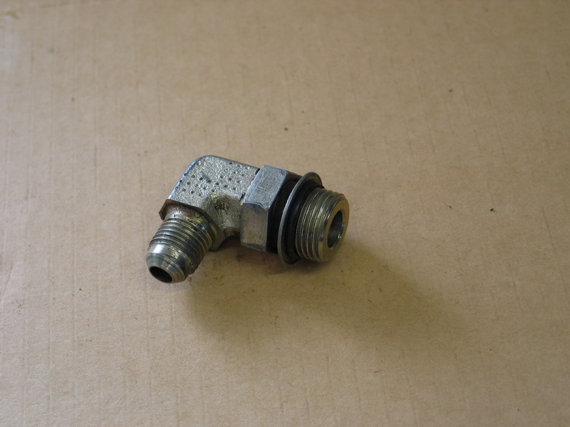 |
Industrial brass ORB to AN/SAE 37 90° adapter. Note the free-running nut and retaining washer above the /-ring and the parallel threads. The separate nut and retaining washer allow for fitting alignment separate from seal tightening. The fitting is screwed into the port and aligned to the desired orientation. The fitting is then held in this orientation and the nut tightened down against the washer, compressing the O-ring into the port's boss creating the seal and securing the fitting in place. This ability to align the fitting to the desired direction, and then tighten it in this orientation is one of the chief benefits of this style of fitting and one of the reasons ORB fittings make such good port fittings. |
||||||||||||||||||||||||||||||||||||||||||||||||||||||||||||||||||||||||||||||||||||||||||||||||||||||||||||||||||||||||||||||||||||||||||||||||||||||||||||||||||||||||||||||||||||||||||||||||||||||||||||||||||||||||||||||||||||||||||||||||||||||||||||||||||||||||||||||||||||||||||||||||||||||||||||||||||||||||||||||||||||||||||||||||||||||||||||||||||||||||||||||||||||||||||||||||||||||||||||||||||||||||||||||||||||||||||||||||||||||||||||||||||||||||||||||||||||||||||||||||||||||||||||||||||||||||||||||||||||||||||||||||||||||||||||||||||||||||||||||||||||||||||||||||||||||||||||||||||||||||||||||||||||||||||||||||||||||||||||||||||||||||||||||||||||||||||||||||||||||||||||||||||||||||||||||||||||||||||||||||||||||||||||||||||||||||||||||||||||||||||||||||||||||||||||||||||||||||||||||||||||||||||||||||||||||||||||||||||||||||||||||||||||||||||||||||||||||||||||||||||||||||||||||||||||||||||||||||||||||||||||||||||||||||||||||||||||||||||||||||||||||||||||||||||||||||||||||||||||||
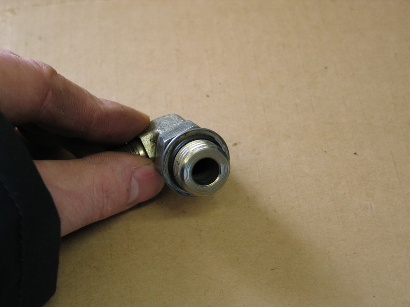 |
ORB. | ||||||||||||||||||||||||||||||||||||||||||||||||||||||||||||||||||||||||||||||||||||||||||||||||||||||||||||||||||||||||||||||||||||||||||||||||||||||||||||||||||||||||||||||||||||||||||||||||||||||||||||||||||||||||||||||||||||||||||||||||||||||||||||||||||||||||||||||||||||||||||||||||||||||||||||||||||||||||||||||||||||||||||||||||||||||||||||||||||||||||||||||||||||||||||||||||||||||||||||||||||||||||||||||||||||||||||||||||||||||||||||||||||||||||||||||||||||||||||||||||||||||||||||||||||||||||||||||||||||||||||||||||||||||||||||||||||||||||||||||||||||||||||||||||||||||||||||||||||||||||||||||||||||||||||||||||||||||||||||||||||||||||||||||||||||||||||||||||||||||||||||||||||||||||||||||||||||||||||||||||||||||||||||||||||||||||||||||||||||||||||||||||||||||||||||||||||||||||||||||||||||||||||||||||||||||||||||||||||||||||||||||||||||||||||||||||||||||||||||||||||||||||||||||||||||||||||||||||||||||||||||||||||||||||||||||||||||||||||||||||||||||||||||||||||||||||||||||||||||||
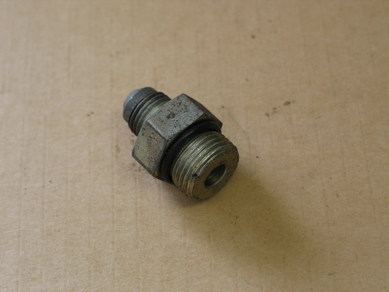 |
Not all ORB fitting have a free-running nut and retaining washer. This fitting is an ORB to AN/SAE 37 adapter. Obviously this style does not enjoy the seperate-align-and-tighten feature. |
||||||||||||||||||||||||||||||||||||||||||||||||||||||||||||||||||||||||||||||||||||||||||||||||||||||||||||||||||||||||||||||||||||||||||||||||||||||||||||||||||||||||||||||||||||||||||||||||||||||||||||||||||||||||||||||||||||||||||||||||||||||||||||||||||||||||||||||||||||||||||||||||||||||||||||||||||||||||||||||||||||||||||||||||||||||||||||||||||||||||||||||||||||||||||||||||||||||||||||||||||||||||||||||||||||||||||||||||||||||||||||||||||||||||||||||||||||||||||||||||||||||||||||||||||||||||||||||||||||||||||||||||||||||||||||||||||||||||||||||||||||||||||||||||||||||||||||||||||||||||||||||||||||||||||||||||||||||||||||||||||||||||||||||||||||||||||||||||||||||||||||||||||||||||||||||||||||||||||||||||||||||||||||||||||||||||||||||||||||||||||||||||||||||||||||||||||||||||||||||||||||||||||||||||||||||||||||||||||||||||||||||||||||||||||||||||||||||||||||||||||||||||||||||||||||||||||||||||||||||||||||||||||||||||||||||||||||||||||||||||||||||||||||||||||||||||||||||||||||||
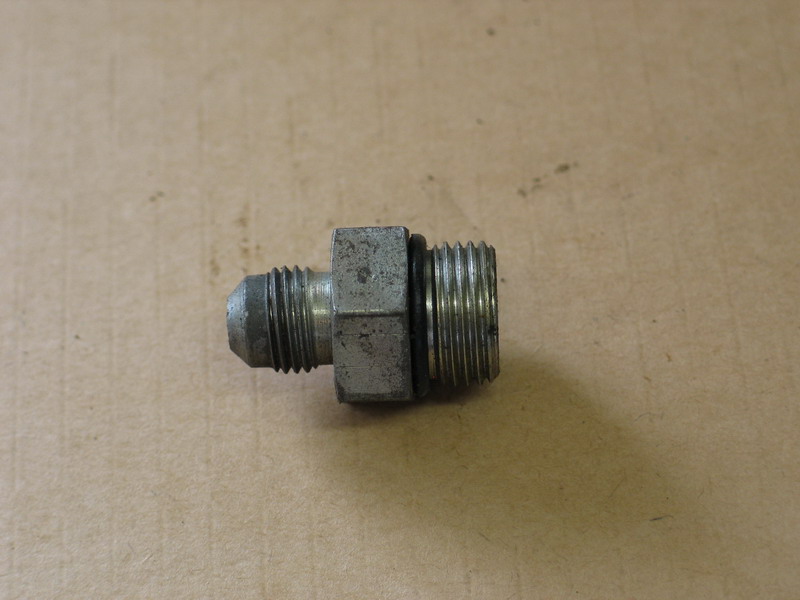 |
ORB to AN/SAE 37 adapter - no free-running nut or retaining washer. | ||||||||||||||||||||||||||||||||||||||||||||||||||||||||||||||||||||||||||||||||||||||||||||||||||||||||||||||||||||||||||||||||||||||||||||||||||||||||||||||||||||||||||||||||||||||||||||||||||||||||||||||||||||||||||||||||||||||||||||||||||||||||||||||||||||||||||||||||||||||||||||||||||||||||||||||||||||||||||||||||||||||||||||||||||||||||||||||||||||||||||||||||||||||||||||||||||||||||||||||||||||||||||||||||||||||||||||||||||||||||||||||||||||||||||||||||||||||||||||||||||||||||||||||||||||||||||||||||||||||||||||||||||||||||||||||||||||||||||||||||||||||||||||||||||||||||||||||||||||||||||||||||||||||||||||||||||||||||||||||||||||||||||||||||||||||||||||||||||||||||||||||||||||||||||||||||||||||||||||||||||||||||||||||||||||||||||||||||||||||||||||||||||||||||||||||||||||||||||||||||||||||||||||||||||||||||||||||||||||||||||||||||||||||||||||||||||||||||||||||||||||||||||||||||||||||||||||||||||||||||||||||||||||||||||||||||||||||||||||||||||||||||||||||||||||||||||||||||||||||
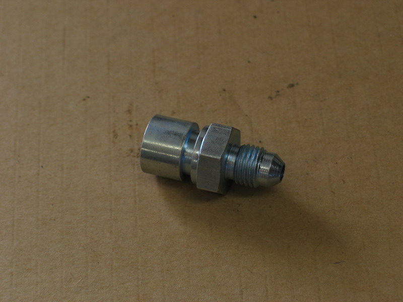 |
Brake line conversion fitting (adapter). This adapter is from 7/16" SAE inverted flare to -03 AN/SAE 37. |
||||||||||||||||||||||||||||||||||||||||||||||||||||||||||||||||||||||||||||||||||||||||||||||||||||||||||||||||||||||||||||||||||||||||||||||||||||||||||||||||||||||||||||||||||||||||||||||||||||||||||||||||||||||||||||||||||||||||||||||||||||||||||||||||||||||||||||||||||||||||||||||||||||||||||||||||||||||||||||||||||||||||||||||||||||||||||||||||||||||||||||||||||||||||||||||||||||||||||||||||||||||||||||||||||||||||||||||||||||||||||||||||||||||||||||||||||||||||||||||||||||||||||||||||||||||||||||||||||||||||||||||||||||||||||||||||||||||||||||||||||||||||||||||||||||||||||||||||||||||||||||||||||||||||||||||||||||||||||||||||||||||||||||||||||||||||||||||||||||||||||||||||||||||||||||||||||||||||||||||||||||||||||||||||||||||||||||||||||||||||||||||||||||||||||||||||||||||||||||||||||||||||||||||||||||||||||||||||||||||||||||||||||||||||||||||||||||||||||||||||||||||||||||||||||||||||||||||||||||||||||||||||||||||||||||||||||||||||||||||||||||||||||||||||||||||||||||||||||||||
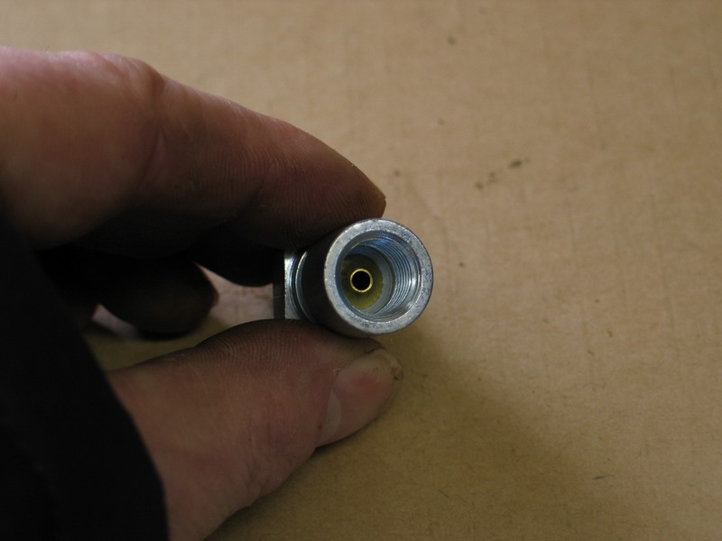 |
Inverted flare seat inside SAE inverted flare to -03 AN/SAE 37 adapter. | ||||||||||||||||||||||||||||||||||||||||||||||||||||||||||||||||||||||||||||||||||||||||||||||||||||||||||||||||||||||||||||||||||||||||||||||||||||||||||||||||||||||||||||||||||||||||||||||||||||||||||||||||||||||||||||||||||||||||||||||||||||||||||||||||||||||||||||||||||||||||||||||||||||||||||||||||||||||||||||||||||||||||||||||||||||||||||||||||||||||||||||||||||||||||||||||||||||||||||||||||||||||||||||||||||||||||||||||||||||||||||||||||||||||||||||||||||||||||||||||||||||||||||||||||||||||||||||||||||||||||||||||||||||||||||||||||||||||||||||||||||||||||||||||||||||||||||||||||||||||||||||||||||||||||||||||||||||||||||||||||||||||||||||||||||||||||||||||||||||||||||||||||||||||||||||||||||||||||||||||||||||||||||||||||||||||||||||||||||||||||||||||||||||||||||||||||||||||||||||||||||||||||||||||||||||||||||||||||||||||||||||||||||||||||||||||||||||||||||||||||||||||||||||||||||||||||||||||||||||||||||||||||||||||||||||||||||||||||||||||||||||||||||||||||||||||||||||||||||||||
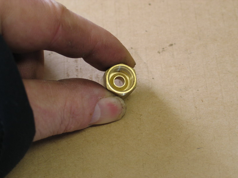 |
Inverted flare seat in SAE inverted flare union - this one for brake lines. | ||||||||||||||||||||||||||||||||||||||||||||||||||||||||||||||||||||||||||||||||||||||||||||||||||||||||||||||||||||||||||||||||||||||||||||||||||||||||||||||||||||||||||||||||||||||||||||||||||||||||||||||||||||||||||||||||||||||||||||||||||||||||||||||||||||||||||||||||||||||||||||||||||||||||||||||||||||||||||||||||||||||||||||||||||||||||||||||||||||||||||||||||||||||||||||||||||||||||||||||||||||||||||||||||||||||||||||||||||||||||||||||||||||||||||||||||||||||||||||||||||||||||||||||||||||||||||||||||||||||||||||||||||||||||||||||||||||||||||||||||||||||||||||||||||||||||||||||||||||||||||||||||||||||||||||||||||||||||||||||||||||||||||||||||||||||||||||||||||||||||||||||||||||||||||||||||||||||||||||||||||||||||||||||||||||||||||||||||||||||||||||||||||||||||||||||||||||||||||||||||||||||||||||||||||||||||||||||||||||||||||||||||||||||||||||||||||||||||||||||||||||||||||||||||||||||||||||||||||||||||||||||||||||||||||||||||||||||||||||||||||||||||||||||||||||||||||||||||||||||
|
Two types of power steering pump outlet / hydroboost brake booster adapters. On the left is an /-ring pilot to AN/SAE 37, without the /-ring installed. On the right is an SAE inverted flare to AN/SAE 37. |
||||||||||||||||||||||||||||||||||||||||||||||||||||||||||||||||||||||||||||||||||||||||||||||||||||||||||||||||||||||||||||||||||||||||||||||||||||||||||||||||||||||||||||||||||||||||||||||||||||||||||||||||||||||||||||||||||||||||||||||||||||||||||||||||||||||||||||||||||||||||||||||||||||||||||||||||||||||||||||||||||||||||||||||||||||||||||||||||||||||||||||||||||||||||||||||||||||||||||||||||||||||||||||||||||||||||||||||||||||||||||||||||||||||||||||||||||||||||||||||||||||||||||||||||||||||||||||||||||||||||||||||||||||||||||||||||||||||||||||||||||||||||||||||||||||||||||||||||||||||||||||||||||||||||||||||||||||||||||||||||||||||||||||||||||||||||||||||||||||||||||||||||||||||||||||||||||||||||||||||||||||||||||||||||||||||||||||||||||||||||||||||||||||||||||||||||||||||||||||||||||||||||||||||||||||||||||||||||||||||||||||||||||||||||||||||||||||||||||||||||||||||||||||||||||||||||||||||||||||||||||||||||||||||||||||||||||||||||||||||||||||||||||||||||||||||||||||||||||||||
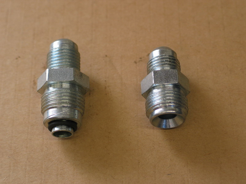 |
On the left is an /-ring pilot to AN/SAE 37, with the /-ring installed. On the right is an SAE inverted flare to AN/SAE 37. |
||||||||||||||||||||||||||||||||||||||||||||||||||||||||||||||||||||||||||||||||||||||||||||||||||||||||||||||||||||||||||||||||||||||||||||||||||||||||||||||||||||||||||||||||||||||||||||||||||||||||||||||||||||||||||||||||||||||||||||||||||||||||||||||||||||||||||||||||||||||||||||||||||||||||||||||||||||||||||||||||||||||||||||||||||||||||||||||||||||||||||||||||||||||||||||||||||||||||||||||||||||||||||||||||||||||||||||||||||||||||||||||||||||||||||||||||||||||||||||||||||||||||||||||||||||||||||||||||||||||||||||||||||||||||||||||||||||||||||||||||||||||||||||||||||||||||||||||||||||||||||||||||||||||||||||||||||||||||||||||||||||||||||||||||||||||||||||||||||||||||||||||||||||||||||||||||||||||||||||||||||||||||||||||||||||||||||||||||||||||||||||||||||||||||||||||||||||||||||||||||||||||||||||||||||||||||||||||||||||||||||||||||||||||||||||||||||||||||||||||||||||||||||||||||||||||||||||||||||||||||||||||||||||||||||||||||||||||||||||||||||||||||||||||||||||||||||||||||||||||
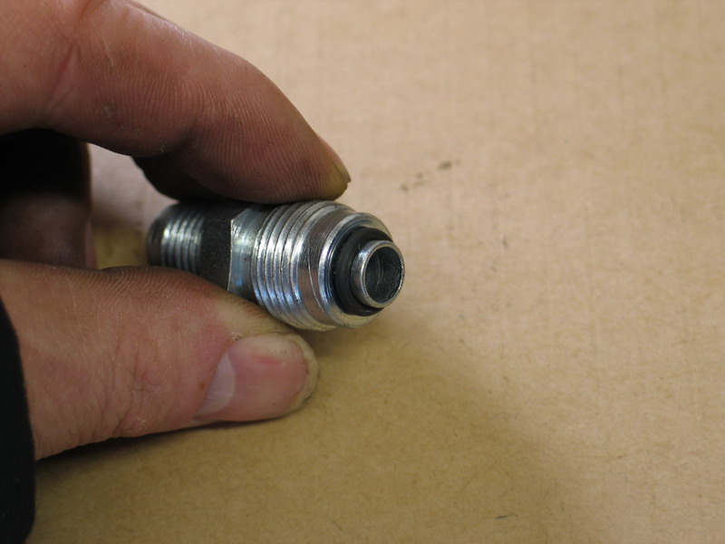 |
/-ring pilot. | ||||||||||||||||||||||||||||||||||||||||||||||||||||||||||||||||||||||||||||||||||||||||||||||||||||||||||||||||||||||||||||||||||||||||||||||||||||||||||||||||||||||||||||||||||||||||||||||||||||||||||||||||||||||||||||||||||||||||||||||||||||||||||||||||||||||||||||||||||||||||||||||||||||||||||||||||||||||||||||||||||||||||||||||||||||||||||||||||||||||||||||||||||||||||||||||||||||||||||||||||||||||||||||||||||||||||||||||||||||||||||||||||||||||||||||||||||||||||||||||||||||||||||||||||||||||||||||||||||||||||||||||||||||||||||||||||||||||||||||||||||||||||||||||||||||||||||||||||||||||||||||||||||||||||||||||||||||||||||||||||||||||||||||||||||||||||||||||||||||||||||||||||||||||||||||||||||||||||||||||||||||||||||||||||||||||||||||||||||||||||||||||||||||||||||||||||||||||||||||||||||||||||||||||||||||||||||||||||||||||||||||||||||||||||||||||||||||||||||||||||||||||||||||||||||||||||||||||||||||||||||||||||||||||||||||||||||||||||||||||||||||||||||||||||||||||||||||||||||||||
 |
SAE Inverted flare. Note the pronounced 45° flare sealing surface. Obviously, this is a male fitting. |
||||||||||||||||||||||||||||||||||||||||||||||||||||||||||||||||||||||||||||||||||||||||||||||||||||||||||||||||||||||||||||||||||||||||||||||||||||||||||||||||||||||||||||||||||||||||||||||||||||||||||||||||||||||||||||||||||||||||||||||||||||||||||||||||||||||||||||||||||||||||||||||||||||||||||||||||||||||||||||||||||||||||||||||||||||||||||||||||||||||||||||||||||||||||||||||||||||||||||||||||||||||||||||||||||||||||||||||||||||||||||||||||||||||||||||||||||||||||||||||||||||||||||||||||||||||||||||||||||||||||||||||||||||||||||||||||||||||||||||||||||||||||||||||||||||||||||||||||||||||||||||||||||||||||||||||||||||||||||||||||||||||||||||||||||||||||||||||||||||||||||||||||||||||||||||||||||||||||||||||||||||||||||||||||||||||||||||||||||||||||||||||||||||||||||||||||||||||||||||||||||||||||||||||||||||||||||||||||||||||||||||||||||||||||||||||||||||||||||||||||||||||||||||||||||||||||||||||||||||||||||||||||||||||||||||||||||||||||||||||||||||||||||||||||||||||||||||||||||||||
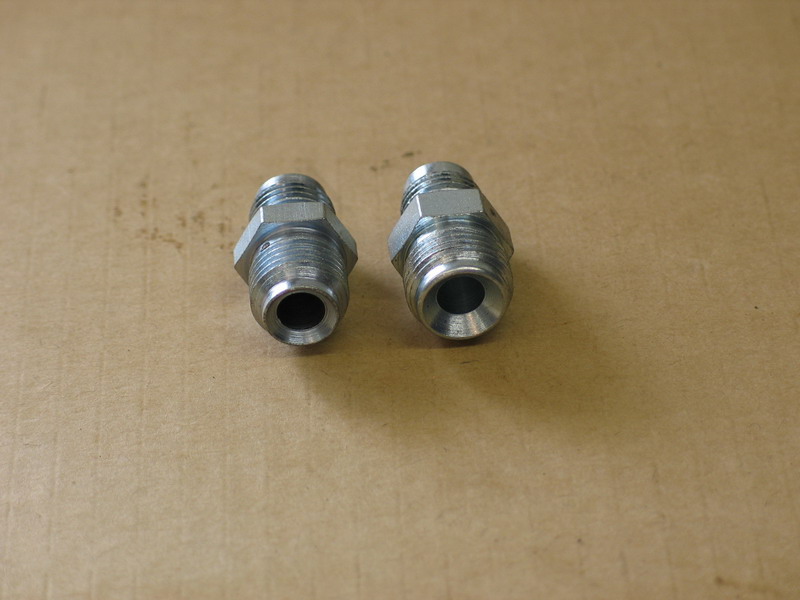 |
Two different sizes of SAE Inverted flare. | ||||||||||||||||||||||||||||||||||||||||||||||||||||||||||||||||||||||||||||||||||||||||||||||||||||||||||||||||||||||||||||||||||||||||||||||||||||||||||||||||||||||||||||||||||||||||||||||||||||||||||||||||||||||||||||||||||||||||||||||||||||||||||||||||||||||||||||||||||||||||||||||||||||||||||||||||||||||||||||||||||||||||||||||||||||||||||||||||||||||||||||||||||||||||||||||||||||||||||||||||||||||||||||||||||||||||||||||||||||||||||||||||||||||||||||||||||||||||||||||||||||||||||||||||||||||||||||||||||||||||||||||||||||||||||||||||||||||||||||||||||||||||||||||||||||||||||||||||||||||||||||||||||||||||||||||||||||||||||||||||||||||||||||||||||||||||||||||||||||||||||||||||||||||||||||||||||||||||||||||||||||||||||||||||||||||||||||||||||||||||||||||||||||||||||||||||||||||||||||||||||||||||||||||||||||||||||||||||||||||||||||||||||||||||||||||||||||||||||||||||||||||||||||||||||||||||||||||||||||||||||||||||||||||||||||||||||||||||||||||||||||||||||||||||||||||||||||||||||||||
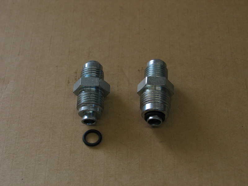 |
Two different sizes of /-ring pilot to AN/SAE 37 adapters. | ||||||||||||||||||||||||||||||||||||||||||||||||||||||||||||||||||||||||||||||||||||||||||||||||||||||||||||||||||||||||||||||||||||||||||||||||||||||||||||||||||||||||||||||||||||||||||||||||||||||||||||||||||||||||||||||||||||||||||||||||||||||||||||||||||||||||||||||||||||||||||||||||||||||||||||||||||||||||||||||||||||||||||||||||||||||||||||||||||||||||||||||||||||||||||||||||||||||||||||||||||||||||||||||||||||||||||||||||||||||||||||||||||||||||||||||||||||||||||||||||||||||||||||||||||||||||||||||||||||||||||||||||||||||||||||||||||||||||||||||||||||||||||||||||||||||||||||||||||||||||||||||||||||||||||||||||||||||||||||||||||||||||||||||||||||||||||||||||||||||||||||||||||||||||||||||||||||||||||||||||||||||||||||||||||||||||||||||||||||||||||||||||||||||||||||||||||||||||||||||||||||||||||||||||||||||||||||||||||||||||||||||||||||||||||||||||||||||||||||||||||||||||||||||||||||||||||||||||||||||||||||||||||||||||||||||||||||||||||||||||||||||||||||||||||||||||||||||||||||||
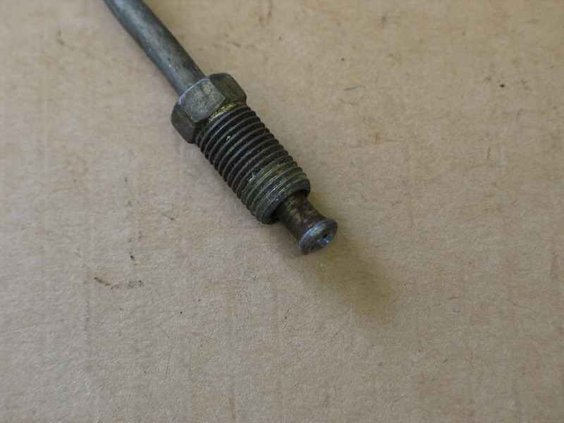 |
This is obviously a brake line. Q: What type of fitting is it? |
||||||||||||||||||||||||||||||||||||||||||||||||||||||||||||||||||||||||||||||||||||||||||||||||||||||||||||||||||||||||||||||||||||||||||||||||||||||||||||||||||||||||||||||||||||||||||||||||||||||||||||||||||||||||||||||||||||||||||||||||||||||||||||||||||||||||||||||||||||||||||||||||||||||||||||||||||||||||||||||||||||||||||||||||||||||||||||||||||||||||||||||||||||||||||||||||||||||||||||||||||||||||||||||||||||||||||||||||||||||||||||||||||||||||||||||||||||||||||||||||||||||||||||||||||||||||||||||||||||||||||||||||||||||||||||||||||||||||||||||||||||||||||||||||||||||||||||||||||||||||||||||||||||||||||||||||||||||||||||||||||||||||||||||||||||||||||||||||||||||||||||||||||||||||||||||||||||||||||||||||||||||||||||||||||||||||||||||||||||||||||||||||||||||||||||||||||||||||||||||||||||||||||||||||||||||||||||||||||||||||||||||||||||||||||||||||||||||||||||||||||||||||||||||||||||||||||||||||||||||||||||||||||||||||||||||||||||||||||||||||||||||||||||||||||||||||||||||||||||||
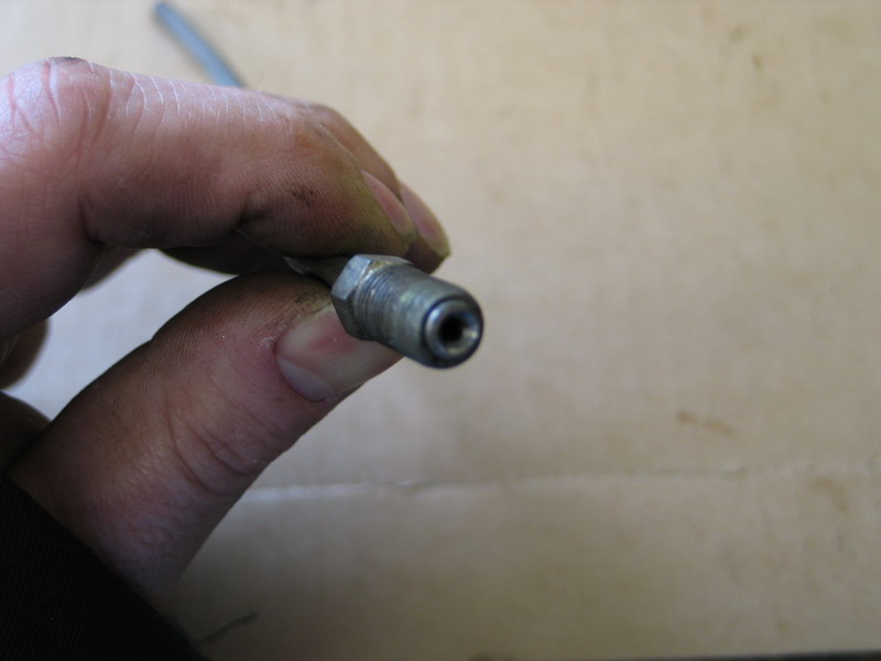 |
A: SAE inverted flare. | ||||||||||||||||||||||||||||||||||||||||||||||||||||||||||||||||||||||||||||||||||||||||||||||||||||||||||||||||||||||||||||||||||||||||||||||||||||||||||||||||||||||||||||||||||||||||||||||||||||||||||||||||||||||||||||||||||||||||||||||||||||||||||||||||||||||||||||||||||||||||||||||||||||||||||||||||||||||||||||||||||||||||||||||||||||||||||||||||||||||||||||||||||||||||||||||||||||||||||||||||||||||||||||||||||||||||||||||||||||||||||||||||||||||||||||||||||||||||||||||||||||||||||||||||||||||||||||||||||||||||||||||||||||||||||||||||||||||||||||||||||||||||||||||||||||||||||||||||||||||||||||||||||||||||||||||||||||||||||||||||||||||||||||||||||||||||||||||||||||||||||||||||||||||||||||||||||||||||||||||||||||||||||||||||||||||||||||||||||||||||||||||||||||||||||||||||||||||||||||||||||||||||||||||||||||||||||||||||||||||||||||||||||||||||||||||||||||||||||||||||||||||||||||||||||||||||||||||||||||||||||||||||||||||||||||||||||||||||||||||||||||||||||||||||||||||||||||||||||||||
 |
NPSM to SAE inverted flare adapter on the left. This one from a TH400 automatic transmission cooler line. The NPSM end screws into the TH400 case, the SAE inverted flare is the fitting on the end of the transmission cooler line. |
||||||||||||||||||||||||||||||||||||||||||||||||||||||||||||||||||||||||||||||||||||||||||||||||||||||||||||||||||||||||||||||||||||||||||||||||||||||||||||||||||||||||||||||||||||||||||||||||||||||||||||||||||||||||||||||||||||||||||||||||||||||||||||||||||||||||||||||||||||||||||||||||||||||||||||||||||||||||||||||||||||||||||||||||||||||||||||||||||||||||||||||||||||||||||||||||||||||||||||||||||||||||||||||||||||||||||||||||||||||||||||||||||||||||||||||||||||||||||||||||||||||||||||||||||||||||||||||||||||||||||||||||||||||||||||||||||||||||||||||||||||||||||||||||||||||||||||||||||||||||||||||||||||||||||||||||||||||||||||||||||||||||||||||||||||||||||||||||||||||||||||||||||||||||||||||||||||||||||||||||||||||||||||||||||||||||||||||||||||||||||||||||||||||||||||||||||||||||||||||||||||||||||||||||||||||||||||||||||||||||||||||||||||||||||||||||||||||||||||||||||||||||||||||||||||||||||||||||||||||||||||||||||||||||||||||||||||||||||||||||||||||||||||||||||||||||||||||||||||||
 |
NPSM to SAE inverted flare adapter - note the shiny surface under the hex, where the sealing washer was located. | ||||||||||||||||||||||||||||||||||||||||||||||||||||||||||||||||||||||||||||||||||||||||||||||||||||||||||||||||||||||||||||||||||||||||||||||||||||||||||||||||||||||||||||||||||||||||||||||||||||||||||||||||||||||||||||||||||||||||||||||||||||||||||||||||||||||||||||||||||||||||||||||||||||||||||||||||||||||||||||||||||||||||||||||||||||||||||||||||||||||||||||||||||||||||||||||||||||||||||||||||||||||||||||||||||||||||||||||||||||||||||||||||||||||||||||||||||||||||||||||||||||||||||||||||||||||||||||||||||||||||||||||||||||||||||||||||||||||||||||||||||||||||||||||||||||||||||||||||||||||||||||||||||||||||||||||||||||||||||||||||||||||||||||||||||||||||||||||||||||||||||||||||||||||||||||||||||||||||||||||||||||||||||||||||||||||||||||||||||||||||||||||||||||||||||||||||||||||||||||||||||||||||||||||||||||||||||||||||||||||||||||||||||||||||||||||||||||||||||||||||||||||||||||||||||||||||||||||||||||||||||||||||||||||||||||||||||||||||||||||||||||||||||||||||||||||||||||||||||||||
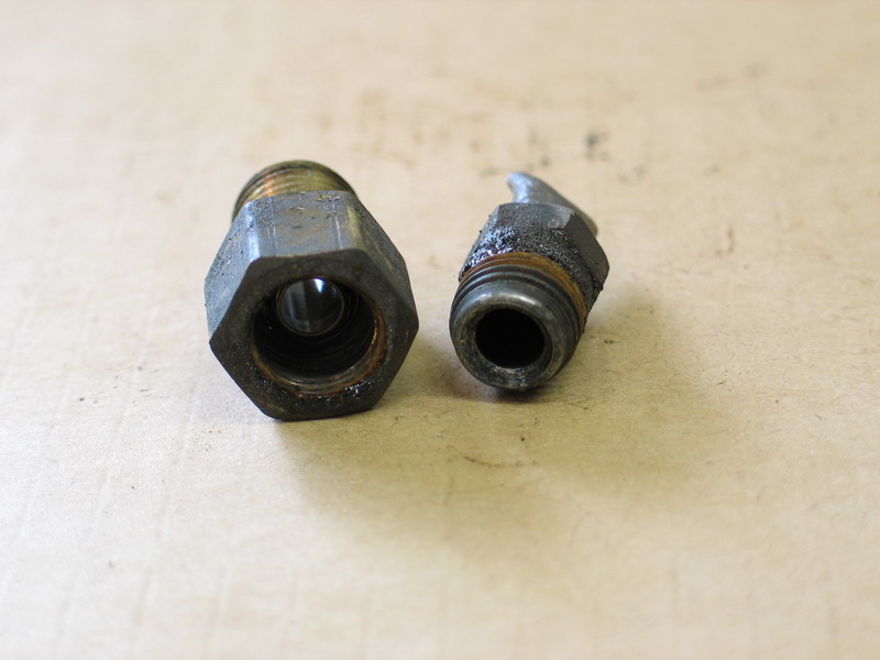 |
SAE inverted flare side of the TH400 transmission cooler line adapter. | ||||||||||||||||||||||||||||||||||||||||||||||||||||||||||||||||||||||||||||||||||||||||||||||||||||||||||||||||||||||||||||||||||||||||||||||||||||||||||||||||||||||||||||||||||||||||||||||||||||||||||||||||||||||||||||||||||||||||||||||||||||||||||||||||||||||||||||||||||||||||||||||||||||||||||||||||||||||||||||||||||||||||||||||||||||||||||||||||||||||||||||||||||||||||||||||||||||||||||||||||||||||||||||||||||||||||||||||||||||||||||||||||||||||||||||||||||||||||||||||||||||||||||||||||||||||||||||||||||||||||||||||||||||||||||||||||||||||||||||||||||||||||||||||||||||||||||||||||||||||||||||||||||||||||||||||||||||||||||||||||||||||||||||||||||||||||||||||||||||||||||||||||||||||||||||||||||||||||||||||||||||||||||||||||||||||||||||||||||||||||||||||||||||||||||||||||||||||||||||||||||||||||||||||||||||||||||||||||||||||||||||||||||||||||||||||||||||||||||||||||||||||||||||||||||||||||||||||||||||||||||||||||||||||||||||||||||||||||||||||||||||||||||||||||||||||||||||||||||||||
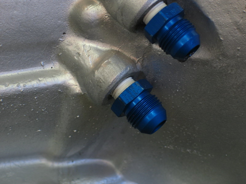 |
NPT to AN/SAE 37 adapters - screwed into NPSM ports in TH400 case with plenty of Teflon tape sealant. Checking the theory that one can screw an NPT male fitting into an NPSM port and still achieve a satisfactory seal. |
||||||||||||||||||||||||||||||||||||||||||||||||||||||||||||||||||||||||||||||||||||||||||||||||||||||||||||||||||||||||||||||||||||||||||||||||||||||||||||||||||||||||||||||||||||||||||||||||||||||||||||||||||||||||||||||||||||||||||||||||||||||||||||||||||||||||||||||||||||||||||||||||||||||||||||||||||||||||||||||||||||||||||||||||||||||||||||||||||||||||||||||||||||||||||||||||||||||||||||||||||||||||||||||||||||||||||||||||||||||||||||||||||||||||||||||||||||||||||||||||||||||||||||||||||||||||||||||||||||||||||||||||||||||||||||||||||||||||||||||||||||||||||||||||||||||||||||||||||||||||||||||||||||||||||||||||||||||||||||||||||||||||||||||||||||||||||||||||||||||||||||||||||||||||||||||||||||||||||||||||||||||||||||||||||||||||||||||||||||||||||||||||||||||||||||||||||||||||||||||||||||||||||||||||||||||||||||||||||||||||||||||||||||||||||||||||||||||||||||||||||||||||||||||||||||||||||||||||||||||||||||||||||||||||||||||||||||||||||||||||||||||||||||||||||||||||||||||||||||||
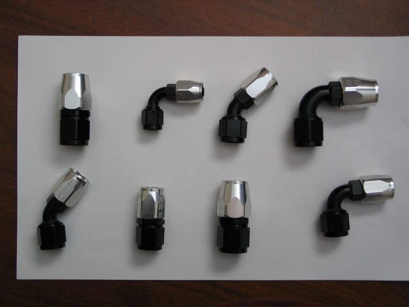 |
Various AN/SAE 37 re-usable (field attachable) hose-ends. These are Russell Performance "full flow" hose-ends in aluminum. |
||||||||||||||||||||||||||||||||||||||||||||||||||||||||||||||||||||||||||||||||||||||||||||||||||||||||||||||||||||||||||||||||||||||||||||||||||||||||||||||||||||||||||||||||||||||||||||||||||||||||||||||||||||||||||||||||||||||||||||||||||||||||||||||||||||||||||||||||||||||||||||||||||||||||||||||||||||||||||||||||||||||||||||||||||||||||||||||||||||||||||||||||||||||||||||||||||||||||||||||||||||||||||||||||||||||||||||||||||||||||||||||||||||||||||||||||||||||||||||||||||||||||||||||||||||||||||||||||||||||||||||||||||||||||||||||||||||||||||||||||||||||||||||||||||||||||||||||||||||||||||||||||||||||||||||||||||||||||||||||||||||||||||||||||||||||||||||||||||||||||||||||||||||||||||||||||||||||||||||||||||||||||||||||||||||||||||||||||||||||||||||||||||||||||||||||||||||||||||||||||||||||||||||||||||||||||||||||||||||||||||||||||||||||||||||||||||||||||||||||||||||||||||||||||||||||||||||||||||||||||||||||||||||||||||||||||||||||||||||||||||||||||||||||||||||||||||||||||||||||
How to Identify FittingsThe process of identifying an unknown fitting is a multi-step procedure as detailed below that involves taking some empirical measurements and comparing the results to the data contained in the fitting tables above. Step 1 - carefully examine the fitting for any markings or a part number that may aid in identification. Step 2 - examine the fitting for features that will narrow down the possibilities, such as:
Step 3 - measure and categorize the threads as follows: |
|||||||||||||||||||||||||||||||||||||||||||||||||||||||||||||||||||||||||||||||||||||||||||||||||||||||||||||||||||||||||||||||||||||||||||||||||||||||||||||||||||||||||||||||||||||||||||||||||||||||||||||||||||||||||||||||||||||||||||||||||||||||||||||||||||||||||||||||||||||||||||||||||||||||||||||||||||||||||||||||||||||||||||||||||||||||||||||||||||||||||||||||||||||||||||||||||||||||||||||||||||||||||||||||||||||||||||||||||||||||||||||||||||||||||||||||||||||||||||||||||||||||||||||||||||||||||||||||||||||||||||||||||||||||||||||||||||||||||||||||||||||||||||||||||||||||||||||||||||||||||||||||||||||||||||||||||||||||||||||||||||||||||||||||||||||||||||||||||||||||||||||||||||||||||||||||||||||||||||||||||||||||||||||||||||||||||||||||||||||||||||||||||||||||||||||||||||||||||||||||||||||||||||||||||||||||||||||||||||||||||||||||||||||||||||||||||||||||||||||||||||||||||||||||||||||||||||||||||||||||||||||||||||||||||||||||||||||||||||||||||||||||||||||||||||||||||||||||||||||||
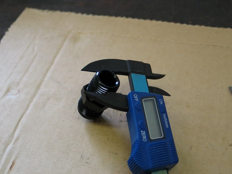 |
Measure the OD of the threads (or the ID in the case of a female fitting) and... | ||||||||||||||||||||||||||||||||||||||||||||||||||||||||||||||||||||||||||||||||||||||||||||||||||||||||||||||||||||||||||||||||||||||||||||||||||||||||||||||||||||||||||||||||||||||||||||||||||||||||||||||||||||||||||||||||||||||||||||||||||||||||||||||||||||||||||||||||||||||||||||||||||||||||||||||||||||||||||||||||||||||||||||||||||||||||||||||||||||||||||||||||||||||||||||||||||||||||||||||||||||||||||||||||||||||||||||||||||||||||||||||||||||||||||||||||||||||||||||||||||||||||||||||||||||||||||||||||||||||||||||||||||||||||||||||||||||||||||||||||||||||||||||||||||||||||||||||||||||||||||||||||||||||||||||||||||||||||||||||||||||||||||||||||||||||||||||||||||||||||||||||||||||||||||||||||||||||||||||||||||||||||||||||||||||||||||||||||||||||||||||||||||||||||||||||||||||||||||||||||||||||||||||||||||||||||||||||||||||||||||||||||||||||||||||||||||||||||||||||||||||||||||||||||||||||||||||||||||||||||||||||||||||||||||||||||||||||||||||||||||||||||||||||||||||||||||||||||||||||
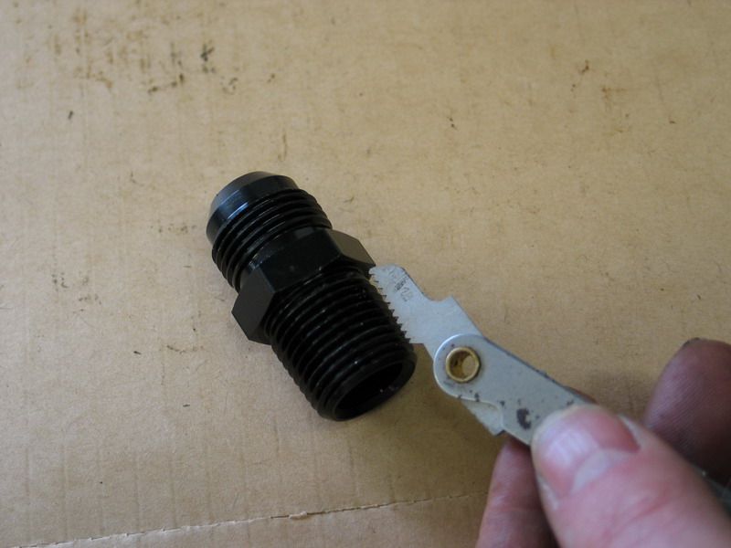 |
... measure the pitch of the threads (or TPI) using a thread gauge. | ||||||||||||||||||||||||||||||||||||||||||||||||||||||||||||||||||||||||||||||||||||||||||||||||||||||||||||||||||||||||||||||||||||||||||||||||||||||||||||||||||||||||||||||||||||||||||||||||||||||||||||||||||||||||||||||||||||||||||||||||||||||||||||||||||||||||||||||||||||||||||||||||||||||||||||||||||||||||||||||||||||||||||||||||||||||||||||||||||||||||||||||||||||||||||||||||||||||||||||||||||||||||||||||||||||||||||||||||||||||||||||||||||||||||||||||||||||||||||||||||||||||||||||||||||||||||||||||||||||||||||||||||||||||||||||||||||||||||||||||||||||||||||||||||||||||||||||||||||||||||||||||||||||||||||||||||||||||||||||||||||||||||||||||||||||||||||||||||||||||||||||||||||||||||||||||||||||||||||||||||||||||||||||||||||||||||||||||||||||||||||||||||||||||||||||||||||||||||||||||||||||||||||||||||||||||||||||||||||||||||||||||||||||||||||||||||||||||||||||||||||||||||||||||||||||||||||||||||||||||||||||||||||||||||||||||||||||||||||||||||||||||||||||||||||||||||||||||||||||||
In addition to measuring the OD / ID and pitch, if the tools are available, you can also use:
Step 4 - measure the angle of the sealing surface. Special gauges are available for this purpose. |
|||||||||||||||||||||||||||||||||||||||||||||||||||||||||||||||||||||||||||||||||||||||||||||||||||||||||||||||||||||||||||||||||||||||||||||||||||||||||||||||||||||||||||||||||||||||||||||||||||||||||||||||||||||||||||||||||||||||||||||||||||||||||||||||||||||||||||||||||||||||||||||||||||||||||||||||||||||||||||||||||||||||||||||||||||||||||||||||||||||||||||||||||||||||||||||||||||||||||||||||||||||||||||||||||||||||||||||||||||||||||||||||||||||||||||||||||||||||||||||||||||||||||||||||||||||||||||||||||||||||||||||||||||||||||||||||||||||||||||||||||||||||||||||||||||||||||||||||||||||||||||||||||||||||||||||||||||||||||||||||||||||||||||||||||||||||||||||||||||||||||||||||||||||||||||||||||||||||||||||||||||||||||||||||||||||||||||||||||||||||||||||||||||||||||||||||||||||||||||||||||||||||||||||||||||||||||||||||||||||||||||||||||||||||||||||||||||||||||||||||||||||||||||||||||||||||||||||||||||||||||||||||||||||||||||||||||||||||||||||||||||||||||||||||||||||||||||||||||||||||
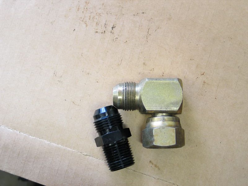 |
However, if you don't have a sealing surface angle gauge, an approximation can be made by comparing the angle of the sealing surface with that of a fitting whose angle is known. | ||||||||||||||||||||||||||||||||||||||||||||||||||||||||||||||||||||||||||||||||||||||||||||||||||||||||||||||||||||||||||||||||||||||||||||||||||||||||||||||||||||||||||||||||||||||||||||||||||||||||||||||||||||||||||||||||||||||||||||||||||||||||||||||||||||||||||||||||||||||||||||||||||||||||||||||||||||||||||||||||||||||||||||||||||||||||||||||||||||||||||||||||||||||||||||||||||||||||||||||||||||||||||||||||||||||||||||||||||||||||||||||||||||||||||||||||||||||||||||||||||||||||||||||||||||||||||||||||||||||||||||||||||||||||||||||||||||||||||||||||||||||||||||||||||||||||||||||||||||||||||||||||||||||||||||||||||||||||||||||||||||||||||||||||||||||||||||||||||||||||||||||||||||||||||||||||||||||||||||||||||||||||||||||||||||||||||||||||||||||||||||||||||||||||||||||||||||||||||||||||||||||||||||||||||||||||||||||||||||||||||||||||||||||||||||||||||||||||||||||||||||||||||||||||||||||||||||||||||||||||||||||||||||||||||||||||||||||||||||||||||||||||||||||||||||||||||||||||||||||
Step 5 - refer to tables. Using all the data collected in steps 2,3, and 4 - compare these results with the data in the tables above for each style of fitting. You should be able to determine a match at this point. Step 6 - verify. Once you have the fitting identified, you can double check your result by attempting to mate the fitting with one of the same size and style as that which you believe it to be. Hose Assembly ConstructionThe beauty of creating custom hose assemblies with Russell Performance hose and full-flow hose-ends is that it is extremely easy to do so. Nevertheless, there are a few tips and tricks worth sharing. The procedure shown below uses Russell Performance Proflex stainless-steel braided hose and ProClassic full-flow hose-ends. |
|||||||||||||||||||||||||||||||||||||||||||||||||||||||||||||||||||||||||||||||||||||||||||||||||||||||||||||||||||||||||||||||||||||||||||||||||||||||||||||||||||||||||||||||||||||||||||||||||||||||||||||||||||||||||||||||||||||||||||||||||||||||||||||||||||||||||||||||||||||||||||||||||||||||||||||||||||||||||||||||||||||||||||||||||||||||||||||||||||||||||||||||||||||||||||||||||||||||||||||||||||||||||||||||||||||||||||||||||||||||||||||||||||||||||||||||||||||||||||||||||||||||||||||||||||||||||||||||||||||||||||||||||||||||||||||||||||||||||||||||||||||||||||||||||||||||||||||||||||||||||||||||||||||||||||||||||||||||||||||||||||||||||||||||||||||||||||||||||||||||||||||||||||||||||||||||||||||||||||||||||||||||||||||||||||||||||||||||||||||||||||||||||||||||||||||||||||||||||||||||||||||||||||||||||||||||||||||||||||||||||||||||||||||||||||||||||||||||||||||||||||||||||||||||||||||||||||||||||||||||||||||||||||||||||||||||||||||||||||||||||||||||||||||||||||||||||||||||||||||||
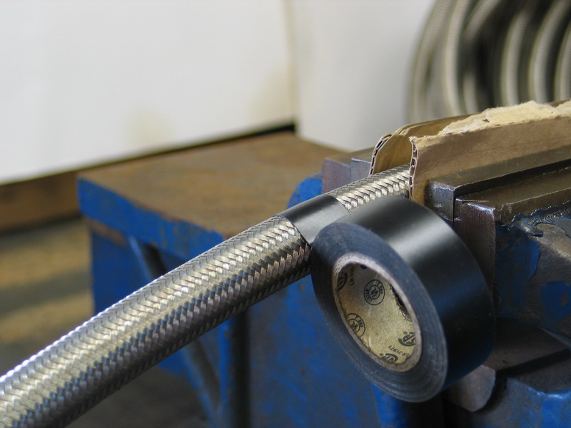 |
Before cutting the hose, wrap twice with electrical tape at the point where the cut is to be made. I have found electrical tape works best, although you can use other tapes such as masking tape. Avoid using tapes with heavy glue residues, such as duct tape. |
||||||||||||||||||||||||||||||||||||||||||||||||||||||||||||||||||||||||||||||||||||||||||||||||||||||||||||||||||||||||||||||||||||||||||||||||||||||||||||||||||||||||||||||||||||||||||||||||||||||||||||||||||||||||||||||||||||||||||||||||||||||||||||||||||||||||||||||||||||||||||||||||||||||||||||||||||||||||||||||||||||||||||||||||||||||||||||||||||||||||||||||||||||||||||||||||||||||||||||||||||||||||||||||||||||||||||||||||||||||||||||||||||||||||||||||||||||||||||||||||||||||||||||||||||||||||||||||||||||||||||||||||||||||||||||||||||||||||||||||||||||||||||||||||||||||||||||||||||||||||||||||||||||||||||||||||||||||||||||||||||||||||||||||||||||||||||||||||||||||||||||||||||||||||||||||||||||||||||||||||||||||||||||||||||||||||||||||||||||||||||||||||||||||||||||||||||||||||||||||||||||||||||||||||||||||||||||||||||||||||||||||||||||||||||||||||||||||||||||||||||||||||||||||||||||||||||||||||||||||||||||||||||||||||||||||||||||||||||||||||||||||||||||||||||||||||||||||||||||||
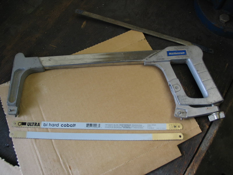 |
There are two ways to cut the hose - either by hand using a hacksaw or by using an abrasive cut-off wheel in an electrical or pneumatic power tool. It will become immediately apparent which method I favour and why. However, if you are going to use a hack saw, one tip is to install two blades facing in opposing directions. |
||||||||||||||||||||||||||||||||||||||||||||||||||||||||||||||||||||||||||||||||||||||||||||||||||||||||||||||||||||||||||||||||||||||||||||||||||||||||||||||||||||||||||||||||||||||||||||||||||||||||||||||||||||||||||||||||||||||||||||||||||||||||||||||||||||||||||||||||||||||||||||||||||||||||||||||||||||||||||||||||||||||||||||||||||||||||||||||||||||||||||||||||||||||||||||||||||||||||||||||||||||||||||||||||||||||||||||||||||||||||||||||||||||||||||||||||||||||||||||||||||||||||||||||||||||||||||||||||||||||||||||||||||||||||||||||||||||||||||||||||||||||||||||||||||||||||||||||||||||||||||||||||||||||||||||||||||||||||||||||||||||||||||||||||||||||||||||||||||||||||||||||||||||||||||||||||||||||||||||||||||||||||||||||||||||||||||||||||||||||||||||||||||||||||||||||||||||||||||||||||||||||||||||||||||||||||||||||||||||||||||||||||||||||||||||||||||||||||||||||||||||||||||||||||||||||||||||||||||||||||||||||||||||||||||||||||||||||||||||||||||||||||||||||||||||||||||||||||||||||
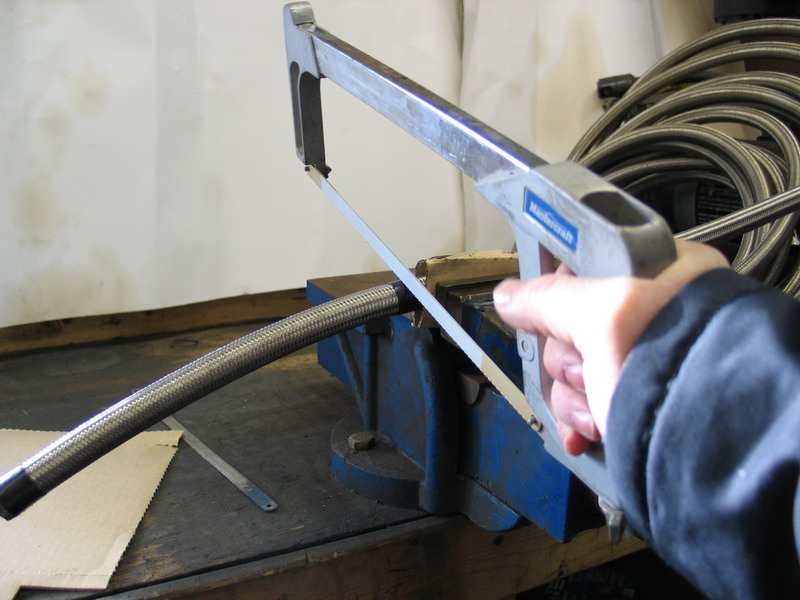 |
With the hose lightly clamped in a vice, make the cut. Be careful not to over-tighten the vice and crush the hose. |
||||||||||||||||||||||||||||||||||||||||||||||||||||||||||||||||||||||||||||||||||||||||||||||||||||||||||||||||||||||||||||||||||||||||||||||||||||||||||||||||||||||||||||||||||||||||||||||||||||||||||||||||||||||||||||||||||||||||||||||||||||||||||||||||||||||||||||||||||||||||||||||||||||||||||||||||||||||||||||||||||||||||||||||||||||||||||||||||||||||||||||||||||||||||||||||||||||||||||||||||||||||||||||||||||||||||||||||||||||||||||||||||||||||||||||||||||||||||||||||||||||||||||||||||||||||||||||||||||||||||||||||||||||||||||||||||||||||||||||||||||||||||||||||||||||||||||||||||||||||||||||||||||||||||||||||||||||||||||||||||||||||||||||||||||||||||||||||||||||||||||||||||||||||||||||||||||||||||||||||||||||||||||||||||||||||||||||||||||||||||||||||||||||||||||||||||||||||||||||||||||||||||||||||||||||||||||||||||||||||||||||||||||||||||||||||||||||||||||||||||||||||||||||||||||||||||||||||||||||||||||||||||||||||||||||||||||||||||||||||||||||||||||||||||||||||||||||||||||||||
 |
If you plan to use a cut-off tool (my preference) the best abrasive cutting wheels are the ultra-thin versions (3/32"). | ||||||||||||||||||||||||||||||||||||||||||||||||||||||||||||||||||||||||||||||||||||||||||||||||||||||||||||||||||||||||||||||||||||||||||||||||||||||||||||||||||||||||||||||||||||||||||||||||||||||||||||||||||||||||||||||||||||||||||||||||||||||||||||||||||||||||||||||||||||||||||||||||||||||||||||||||||||||||||||||||||||||||||||||||||||||||||||||||||||||||||||||||||||||||||||||||||||||||||||||||||||||||||||||||||||||||||||||||||||||||||||||||||||||||||||||||||||||||||||||||||||||||||||||||||||||||||||||||||||||||||||||||||||||||||||||||||||||||||||||||||||||||||||||||||||||||||||||||||||||||||||||||||||||||||||||||||||||||||||||||||||||||||||||||||||||||||||||||||||||||||||||||||||||||||||||||||||||||||||||||||||||||||||||||||||||||||||||||||||||||||||||||||||||||||||||||||||||||||||||||||||||||||||||||||||||||||||||||||||||||||||||||||||||||||||||||||||||||||||||||||||||||||||||||||||||||||||||||||||||||||||||||||||||||||||||||||||||||||||||||||||||||||||||||||||||||||||||||||||||
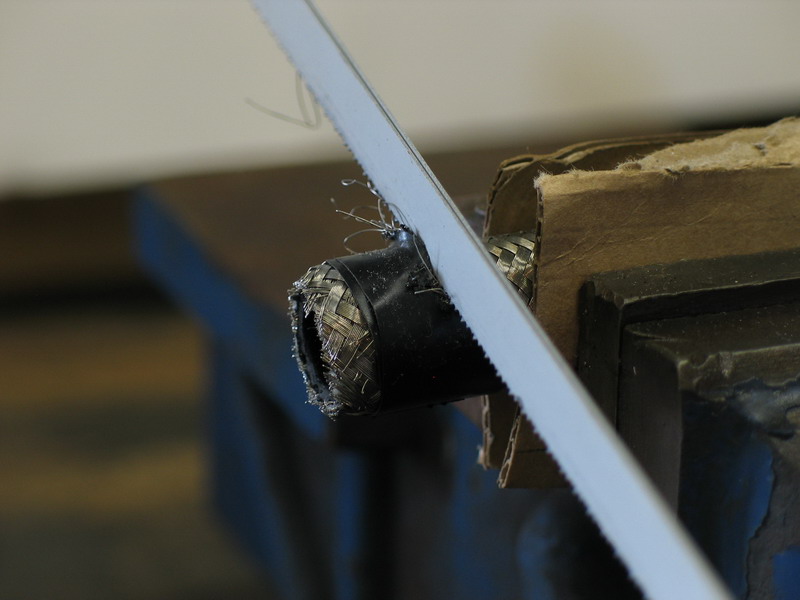 |
Using a hacksaw, I find that no matter what tape I use, what blades I use, or whether there are one or two blades, as soon as I start to cut the outer stainless steel braid begins to go haywire. | ||||||||||||||||||||||||||||||||||||||||||||||||||||||||||||||||||||||||||||||||||||||||||||||||||||||||||||||||||||||||||||||||||||||||||||||||||||||||||||||||||||||||||||||||||||||||||||||||||||||||||||||||||||||||||||||||||||||||||||||||||||||||||||||||||||||||||||||||||||||||||||||||||||||||||||||||||||||||||||||||||||||||||||||||||||||||||||||||||||||||||||||||||||||||||||||||||||||||||||||||||||||||||||||||||||||||||||||||||||||||||||||||||||||||||||||||||||||||||||||||||||||||||||||||||||||||||||||||||||||||||||||||||||||||||||||||||||||||||||||||||||||||||||||||||||||||||||||||||||||||||||||||||||||||||||||||||||||||||||||||||||||||||||||||||||||||||||||||||||||||||||||||||||||||||||||||||||||||||||||||||||||||||||||||||||||||||||||||||||||||||||||||||||||||||||||||||||||||||||||||||||||||||||||||||||||||||||||||||||||||||||||||||||||||||||||||||||||||||||||||||||||||||||||||||||||||||||||||||||||||||||||||||||||||||||||||||||||||||||||||||||||||||||||||||||||||||||||||||||||
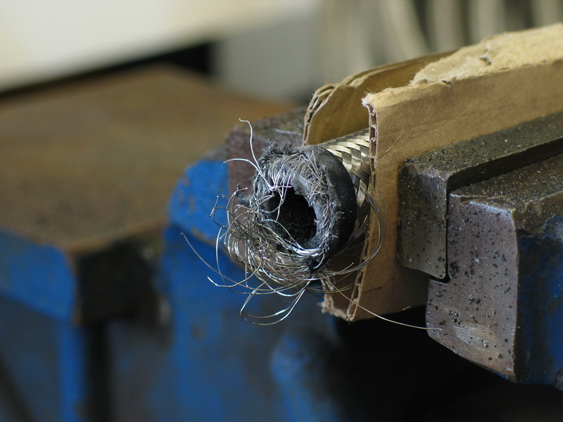 |
Persistence usually leads to a disaster of a finished cut that looks like this. Obviously this is completely useless and cannot be inserted into a fitting. You may have better technique or luck, but I prefer to use an abrasive cut-off tool. |
||||||||||||||||||||||||||||||||||||||||||||||||||||||||||||||||||||||||||||||||||||||||||||||||||||||||||||||||||||||||||||||||||||||||||||||||||||||||||||||||||||||||||||||||||||||||||||||||||||||||||||||||||||||||||||||||||||||||||||||||||||||||||||||||||||||||||||||||||||||||||||||||||||||||||||||||||||||||||||||||||||||||||||||||||||||||||||||||||||||||||||||||||||||||||||||||||||||||||||||||||||||||||||||||||||||||||||||||||||||||||||||||||||||||||||||||||||||||||||||||||||||||||||||||||||||||||||||||||||||||||||||||||||||||||||||||||||||||||||||||||||||||||||||||||||||||||||||||||||||||||||||||||||||||||||||||||||||||||||||||||||||||||||||||||||||||||||||||||||||||||||||||||||||||||||||||||||||||||||||||||||||||||||||||||||||||||||||||||||||||||||||||||||||||||||||||||||||||||||||||||||||||||||||||||||||||||||||||||||||||||||||||||||||||||||||||||||||||||||||||||||||||||||||||||||||||||||||||||||||||||||||||||||||||||||||||||||||||||||||||||||||||||||||||||||||||||||||||||||||
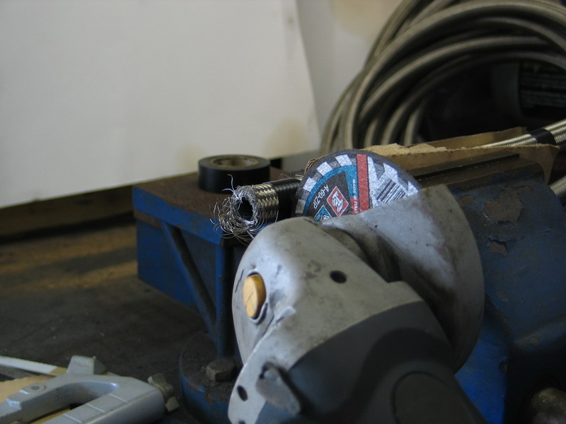 |
The only trick to using the cut-off tool is holding it square to the hose throughout the cut. | ||||||||||||||||||||||||||||||||||||||||||||||||||||||||||||||||||||||||||||||||||||||||||||||||||||||||||||||||||||||||||||||||||||||||||||||||||||||||||||||||||||||||||||||||||||||||||||||||||||||||||||||||||||||||||||||||||||||||||||||||||||||||||||||||||||||||||||||||||||||||||||||||||||||||||||||||||||||||||||||||||||||||||||||||||||||||||||||||||||||||||||||||||||||||||||||||||||||||||||||||||||||||||||||||||||||||||||||||||||||||||||||||||||||||||||||||||||||||||||||||||||||||||||||||||||||||||||||||||||||||||||||||||||||||||||||||||||||||||||||||||||||||||||||||||||||||||||||||||||||||||||||||||||||||||||||||||||||||||||||||||||||||||||||||||||||||||||||||||||||||||||||||||||||||||||||||||||||||||||||||||||||||||||||||||||||||||||||||||||||||||||||||||||||||||||||||||||||||||||||||||||||||||||||||||||||||||||||||||||||||||||||||||||||||||||||||||||||||||||||||||||||||||||||||||||||||||||||||||||||||||||||||||||||||||||||||||||||||||||||||||||||||||||||||||||||||||||||||||||||
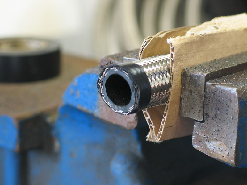 |
Here you can see that I didn't do the best job of that - BUT - you can clearly see the neatness of the cut. | ||||||||||||||||||||||||||||||||||||||||||||||||||||||||||||||||||||||||||||||||||||||||||||||||||||||||||||||||||||||||||||||||||||||||||||||||||||||||||||||||||||||||||||||||||||||||||||||||||||||||||||||||||||||||||||||||||||||||||||||||||||||||||||||||||||||||||||||||||||||||||||||||||||||||||||||||||||||||||||||||||||||||||||||||||||||||||||||||||||||||||||||||||||||||||||||||||||||||||||||||||||||||||||||||||||||||||||||||||||||||||||||||||||||||||||||||||||||||||||||||||||||||||||||||||||||||||||||||||||||||||||||||||||||||||||||||||||||||||||||||||||||||||||||||||||||||||||||||||||||||||||||||||||||||||||||||||||||||||||||||||||||||||||||||||||||||||||||||||||||||||||||||||||||||||||||||||||||||||||||||||||||||||||||||||||||||||||||||||||||||||||||||||||||||||||||||||||||||||||||||||||||||||||||||||||||||||||||||||||||||||||||||||||||||||||||||||||||||||||||||||||||||||||||||||||||||||||||||||||||||||||||||||||||||||||||||||||||||||||||||||||||||||||||||||||||||||||||||||||||
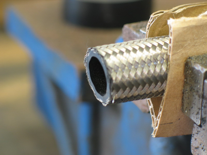 |
With the tape removed, the end of the hose is ready for the hose-end fitting. One caution you must observe if using the abrasive cut method is this: you must carefully blow out, or otherwise clean out of the hose, any debris created by the cutting process. If you expand this pic to full size you can clearly see the abrasive dust and debris left behind after the cut is made. I find that it is easy to blow out with compressed air and / or is easily removed with a Q-tip dipped in a little alcohol. Yes, this is an extra step, but I find the quality of cut well worth the effort. |
||||||||||||||||||||||||||||||||||||||||||||||||||||||||||||||||||||||||||||||||||||||||||||||||||||||||||||||||||||||||||||||||||||||||||||||||||||||||||||||||||||||||||||||||||||||||||||||||||||||||||||||||||||||||||||||||||||||||||||||||||||||||||||||||||||||||||||||||||||||||||||||||||||||||||||||||||||||||||||||||||||||||||||||||||||||||||||||||||||||||||||||||||||||||||||||||||||||||||||||||||||||||||||||||||||||||||||||||||||||||||||||||||||||||||||||||||||||||||||||||||||||||||||||||||||||||||||||||||||||||||||||||||||||||||||||||||||||||||||||||||||||||||||||||||||||||||||||||||||||||||||||||||||||||||||||||||||||||||||||||||||||||||||||||||||||||||||||||||||||||||||||||||||||||||||||||||||||||||||||||||||||||||||||||||||||||||||||||||||||||||||||||||||||||||||||||||||||||||||||||||||||||||||||||||||||||||||||||||||||||||||||||||||||||||||||||||||||||||||||||||||||||||||||||||||||||||||||||||||||||||||||||||||||||||||||||||||||||||||||||||||||||||||||||||||||||||||||||||||||
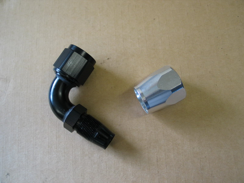 |
With the hose cut and cleaned, it's time to attach the hose-end. Begin by unscrewing the socket (silver part) from the nipple (black part). |
||||||||||||||||||||||||||||||||||||||||||||||||||||||||||||||||||||||||||||||||||||||||||||||||||||||||||||||||||||||||||||||||||||||||||||||||||||||||||||||||||||||||||||||||||||||||||||||||||||||||||||||||||||||||||||||||||||||||||||||||||||||||||||||||||||||||||||||||||||||||||||||||||||||||||||||||||||||||||||||||||||||||||||||||||||||||||||||||||||||||||||||||||||||||||||||||||||||||||||||||||||||||||||||||||||||||||||||||||||||||||||||||||||||||||||||||||||||||||||||||||||||||||||||||||||||||||||||||||||||||||||||||||||||||||||||||||||||||||||||||||||||||||||||||||||||||||||||||||||||||||||||||||||||||||||||||||||||||||||||||||||||||||||||||||||||||||||||||||||||||||||||||||||||||||||||||||||||||||||||||||||||||||||||||||||||||||||||||||||||||||||||||||||||||||||||||||||||||||||||||||||||||||||||||||||||||||||||||||||||||||||||||||||||||||||||||||||||||||||||||||||||||||||||||||||||||||||||||||||||||||||||||||||||||||||||||||||||||||||||||||||||||||||||||||||||||||||||||||||||
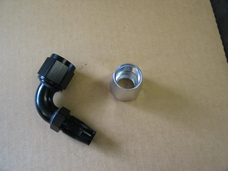 |
Lubricate the threads inside the socket as well as the threads on the nipple with Russell assembly lube. Alternatively you can use a little of the fluid that the system will carry - i.e. clean engine oil or transmission fluid, etc. | ||||||||||||||||||||||||||||||||||||||||||||||||||||||||||||||||||||||||||||||||||||||||||||||||||||||||||||||||||||||||||||||||||||||||||||||||||||||||||||||||||||||||||||||||||||||||||||||||||||||||||||||||||||||||||||||||||||||||||||||||||||||||||||||||||||||||||||||||||||||||||||||||||||||||||||||||||||||||||||||||||||||||||||||||||||||||||||||||||||||||||||||||||||||||||||||||||||||||||||||||||||||||||||||||||||||||||||||||||||||||||||||||||||||||||||||||||||||||||||||||||||||||||||||||||||||||||||||||||||||||||||||||||||||||||||||||||||||||||||||||||||||||||||||||||||||||||||||||||||||||||||||||||||||||||||||||||||||||||||||||||||||||||||||||||||||||||||||||||||||||||||||||||||||||||||||||||||||||||||||||||||||||||||||||||||||||||||||||||||||||||||||||||||||||||||||||||||||||||||||||||||||||||||||||||||||||||||||||||||||||||||||||||||||||||||||||||||||||||||||||||||||||||||||||||||||||||||||||||||||||||||||||||||||||||||||||||||||||||||||||||||||||||||||||||||||||||||||||||||||
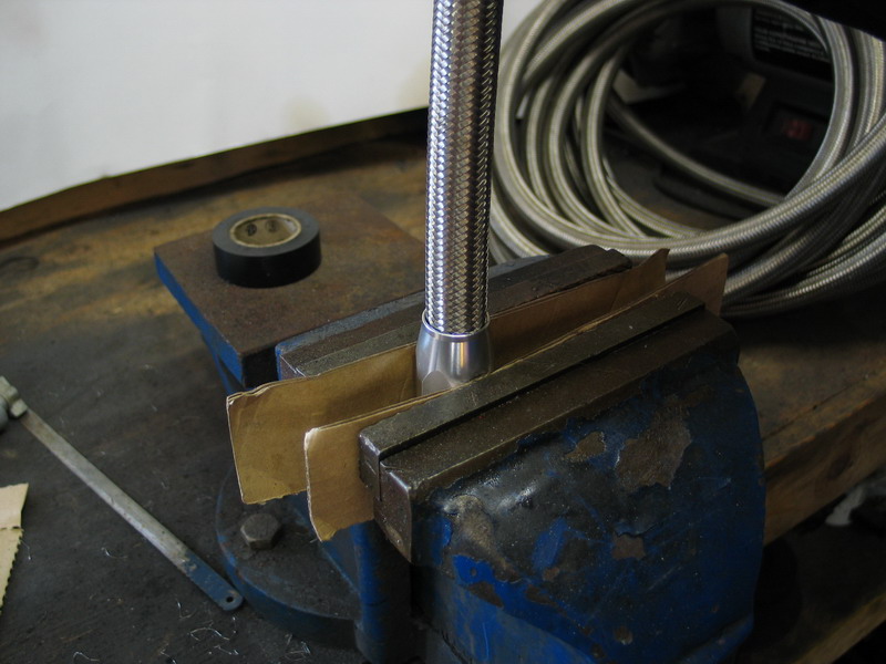 |
The next step is to thread the socket onto the hose. To avoid crushing the hose, it is best to clamp the socket in the vice and thread the hose into the socket. The socket threads are left-hand, so screw the hose in counter-clockwise. Having said that, if the hose is long, screwing it in can be cumbersome... |
||||||||||||||||||||||||||||||||||||||||||||||||||||||||||||||||||||||||||||||||||||||||||||||||||||||||||||||||||||||||||||||||||||||||||||||||||||||||||||||||||||||||||||||||||||||||||||||||||||||||||||||||||||||||||||||||||||||||||||||||||||||||||||||||||||||||||||||||||||||||||||||||||||||||||||||||||||||||||||||||||||||||||||||||||||||||||||||||||||||||||||||||||||||||||||||||||||||||||||||||||||||||||||||||||||||||||||||||||||||||||||||||||||||||||||||||||||||||||||||||||||||||||||||||||||||||||||||||||||||||||||||||||||||||||||||||||||||||||||||||||||||||||||||||||||||||||||||||||||||||||||||||||||||||||||||||||||||||||||||||||||||||||||||||||||||||||||||||||||||||||||||||||||||||||||||||||||||||||||||||||||||||||||||||||||||||||||||||||||||||||||||||||||||||||||||||||||||||||||||||||||||||||||||||||||||||||||||||||||||||||||||||||||||||||||||||||||||||||||||||||||||||||||||||||||||||||||||||||||||||||||||||||||||||||||||||||||||||||||||||||||||||||||||||||||||||||||||||||||||
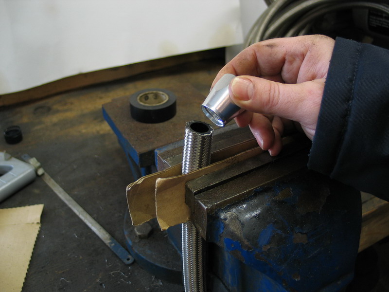 |
... in that case, it can be easier to clamp the hose in the vice and screw the socket on the hose. Be careful not to crush or deform the hose, and remember to screw the socket on counter-clockwise. |
||||||||||||||||||||||||||||||||||||||||||||||||||||||||||||||||||||||||||||||||||||||||||||||||||||||||||||||||||||||||||||||||||||||||||||||||||||||||||||||||||||||||||||||||||||||||||||||||||||||||||||||||||||||||||||||||||||||||||||||||||||||||||||||||||||||||||||||||||||||||||||||||||||||||||||||||||||||||||||||||||||||||||||||||||||||||||||||||||||||||||||||||||||||||||||||||||||||||||||||||||||||||||||||||||||||||||||||||||||||||||||||||||||||||||||||||||||||||||||||||||||||||||||||||||||||||||||||||||||||||||||||||||||||||||||||||||||||||||||||||||||||||||||||||||||||||||||||||||||||||||||||||||||||||||||||||||||||||||||||||||||||||||||||||||||||||||||||||||||||||||||||||||||||||||||||||||||||||||||||||||||||||||||||||||||||||||||||||||||||||||||||||||||||||||||||||||||||||||||||||||||||||||||||||||||||||||||||||||||||||||||||||||||||||||||||||||||||||||||||||||||||||||||||||||||||||||||||||||||||||||||||||||||||||||||||||||||||||||||||||||||||||||||||||||||||||||||||||||||||
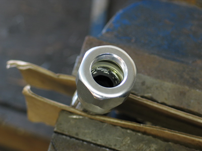 |
Continue to screw the socket on... | ||||||||||||||||||||||||||||||||||||||||||||||||||||||||||||||||||||||||||||||||||||||||||||||||||||||||||||||||||||||||||||||||||||||||||||||||||||||||||||||||||||||||||||||||||||||||||||||||||||||||||||||||||||||||||||||||||||||||||||||||||||||||||||||||||||||||||||||||||||||||||||||||||||||||||||||||||||||||||||||||||||||||||||||||||||||||||||||||||||||||||||||||||||||||||||||||||||||||||||||||||||||||||||||||||||||||||||||||||||||||||||||||||||||||||||||||||||||||||||||||||||||||||||||||||||||||||||||||||||||||||||||||||||||||||||||||||||||||||||||||||||||||||||||||||||||||||||||||||||||||||||||||||||||||||||||||||||||||||||||||||||||||||||||||||||||||||||||||||||||||||||||||||||||||||||||||||||||||||||||||||||||||||||||||||||||||||||||||||||||||||||||||||||||||||||||||||||||||||||||||||||||||||||||||||||||||||||||||||||||||||||||||||||||||||||||||||||||||||||||||||||||||||||||||||||||||||||||||||||||||||||||||||||||||||||||||||||||||||||||||||||||||||||||||||||||||||||||||||||||
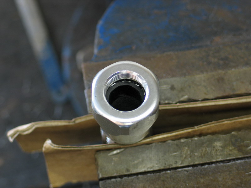 |
...until the hose bottoms inside the socket. You will likely have to use a wrench as the socket tightens on the hose but you don't have to keep screwing until you can't turn it any more. In fact, doing so will damage the hose. | ||||||||||||||||||||||||||||||||||||||||||||||||||||||||||||||||||||||||||||||||||||||||||||||||||||||||||||||||||||||||||||||||||||||||||||||||||||||||||||||||||||||||||||||||||||||||||||||||||||||||||||||||||||||||||||||||||||||||||||||||||||||||||||||||||||||||||||||||||||||||||||||||||||||||||||||||||||||||||||||||||||||||||||||||||||||||||||||||||||||||||||||||||||||||||||||||||||||||||||||||||||||||||||||||||||||||||||||||||||||||||||||||||||||||||||||||||||||||||||||||||||||||||||||||||||||||||||||||||||||||||||||||||||||||||||||||||||||||||||||||||||||||||||||||||||||||||||||||||||||||||||||||||||||||||||||||||||||||||||||||||||||||||||||||||||||||||||||||||||||||||||||||||||||||||||||||||||||||||||||||||||||||||||||||||||||||||||||||||||||||||||||||||||||||||||||||||||||||||||||||||||||||||||||||||||||||||||||||||||||||||||||||||||||||||||||||||||||||||||||||||||||||||||||||||||||||||||||||||||||||||||||||||||||||||||||||||||||||||||||||||||||||||||||||||||||||||||||||||||||
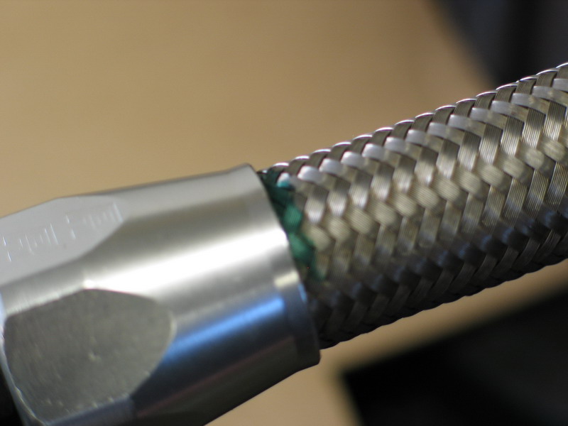 |
With the socket in place on the hose, make an alignment mark on the hose at the end of the socket. | ||||||||||||||||||||||||||||||||||||||||||||||||||||||||||||||||||||||||||||||||||||||||||||||||||||||||||||||||||||||||||||||||||||||||||||||||||||||||||||||||||||||||||||||||||||||||||||||||||||||||||||||||||||||||||||||||||||||||||||||||||||||||||||||||||||||||||||||||||||||||||||||||||||||||||||||||||||||||||||||||||||||||||||||||||||||||||||||||||||||||||||||||||||||||||||||||||||||||||||||||||||||||||||||||||||||||||||||||||||||||||||||||||||||||||||||||||||||||||||||||||||||||||||||||||||||||||||||||||||||||||||||||||||||||||||||||||||||||||||||||||||||||||||||||||||||||||||||||||||||||||||||||||||||||||||||||||||||||||||||||||||||||||||||||||||||||||||||||||||||||||||||||||||||||||||||||||||||||||||||||||||||||||||||||||||||||||||||||||||||||||||||||||||||||||||||||||||||||||||||||||||||||||||||||||||||||||||||||||||||||||||||||||||||||||||||||||||||||||||||||||||||||||||||||||||||||||||||||||||||||||||||||||||||||||||||||||||||||||||||||||||||||||||||||||||||||||||||||||||||
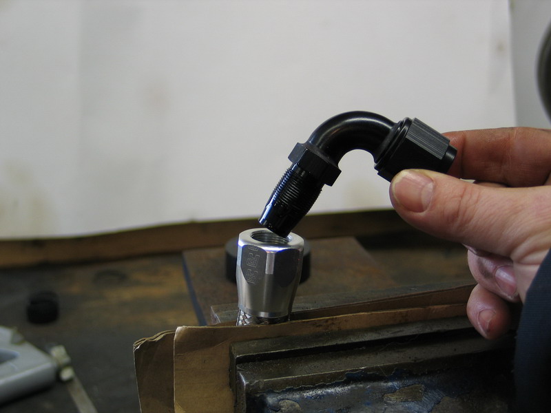 |
With the threads lubed, insert the nipple into the socket. | ||||||||||||||||||||||||||||||||||||||||||||||||||||||||||||||||||||||||||||||||||||||||||||||||||||||||||||||||||||||||||||||||||||||||||||||||||||||||||||||||||||||||||||||||||||||||||||||||||||||||||||||||||||||||||||||||||||||||||||||||||||||||||||||||||||||||||||||||||||||||||||||||||||||||||||||||||||||||||||||||||||||||||||||||||||||||||||||||||||||||||||||||||||||||||||||||||||||||||||||||||||||||||||||||||||||||||||||||||||||||||||||||||||||||||||||||||||||||||||||||||||||||||||||||||||||||||||||||||||||||||||||||||||||||||||||||||||||||||||||||||||||||||||||||||||||||||||||||||||||||||||||||||||||||||||||||||||||||||||||||||||||||||||||||||||||||||||||||||||||||||||||||||||||||||||||||||||||||||||||||||||||||||||||||||||||||||||||||||||||||||||||||||||||||||||||||||||||||||||||||||||||||||||||||||||||||||||||||||||||||||||||||||||||||||||||||||||||||||||||||||||||||||||||||||||||||||||||||||||||||||||||||||||||||||||||||||||||||||||||||||||||||||||||||||||||||||||||||||||||
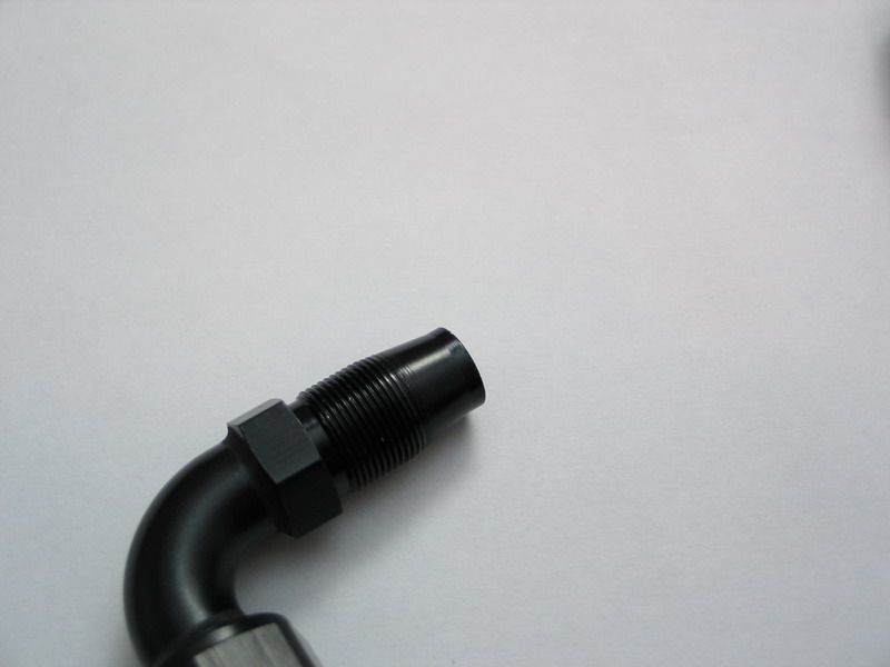 |
The design of the Russell Performance nipple, with taper that flares at the end, makes alignment in hose and socket easy, and eliminates any chance of the dreaded loose flap of rubber in the flow path. | ||||||||||||||||||||||||||||||||||||||||||||||||||||||||||||||||||||||||||||||||||||||||||||||||||||||||||||||||||||||||||||||||||||||||||||||||||||||||||||||||||||||||||||||||||||||||||||||||||||||||||||||||||||||||||||||||||||||||||||||||||||||||||||||||||||||||||||||||||||||||||||||||||||||||||||||||||||||||||||||||||||||||||||||||||||||||||||||||||||||||||||||||||||||||||||||||||||||||||||||||||||||||||||||||||||||||||||||||||||||||||||||||||||||||||||||||||||||||||||||||||||||||||||||||||||||||||||||||||||||||||||||||||||||||||||||||||||||||||||||||||||||||||||||||||||||||||||||||||||||||||||||||||||||||||||||||||||||||||||||||||||||||||||||||||||||||||||||||||||||||||||||||||||||||||||||||||||||||||||||||||||||||||||||||||||||||||||||||||||||||||||||||||||||||||||||||||||||||||||||||||||||||||||||||||||||||||||||||||||||||||||||||||||||||||||||||||||||||||||||||||||||||||||||||||||||||||||||||||||||||||||||||||||||||||||||||||||||||||||||||||||||||||||||||||||||||||||||||||||||
 |
With the socket clamped in the vice, tighten the nipple. | ||||||||||||||||||||||||||||||||||||||||||||||||||||||||||||||||||||||||||||||||||||||||||||||||||||||||||||||||||||||||||||||||||||||||||||||||||||||||||||||||||||||||||||||||||||||||||||||||||||||||||||||||||||||||||||||||||||||||||||||||||||||||||||||||||||||||||||||||||||||||||||||||||||||||||||||||||||||||||||||||||||||||||||||||||||||||||||||||||||||||||||||||||||||||||||||||||||||||||||||||||||||||||||||||||||||||||||||||||||||||||||||||||||||||||||||||||||||||||||||||||||||||||||||||||||||||||||||||||||||||||||||||||||||||||||||||||||||||||||||||||||||||||||||||||||||||||||||||||||||||||||||||||||||||||||||||||||||||||||||||||||||||||||||||||||||||||||||||||||||||||||||||||||||||||||||||||||||||||||||||||||||||||||||||||||||||||||||||||||||||||||||||||||||||||||||||||||||||||||||||||||||||||||||||||||||||||||||||||||||||||||||||||||||||||||||||||||||||||||||||||||||||||||||||||||||||||||||||||||||||||||||||||||||||||||||||||||||||||||||||||||||||||||||||||||||||||||||||||||||
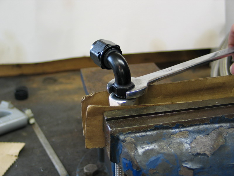 |
As you near the end, you will have to use a wrench. To avoid marring the finish of the hose-end, it is best to use an aluminum AN wrench. |
||||||||||||||||||||||||||||||||||||||||||||||||||||||||||||||||||||||||||||||||||||||||||||||||||||||||||||||||||||||||||||||||||||||||||||||||||||||||||||||||||||||||||||||||||||||||||||||||||||||||||||||||||||||||||||||||||||||||||||||||||||||||||||||||||||||||||||||||||||||||||||||||||||||||||||||||||||||||||||||||||||||||||||||||||||||||||||||||||||||||||||||||||||||||||||||||||||||||||||||||||||||||||||||||||||||||||||||||||||||||||||||||||||||||||||||||||||||||||||||||||||||||||||||||||||||||||||||||||||||||||||||||||||||||||||||||||||||||||||||||||||||||||||||||||||||||||||||||||||||||||||||||||||||||||||||||||||||||||||||||||||||||||||||||||||||||||||||||||||||||||||||||||||||||||||||||||||||||||||||||||||||||||||||||||||||||||||||||||||||||||||||||||||||||||||||||||||||||||||||||||||||||||||||||||||||||||||||||||||||||||||||||||||||||||||||||||||||||||||||||||||||||||||||||||||||||||||||||||||||||||||||||||||||||||||||||||||||||||||||||||||||||||||||||||||||||||||||||||||||
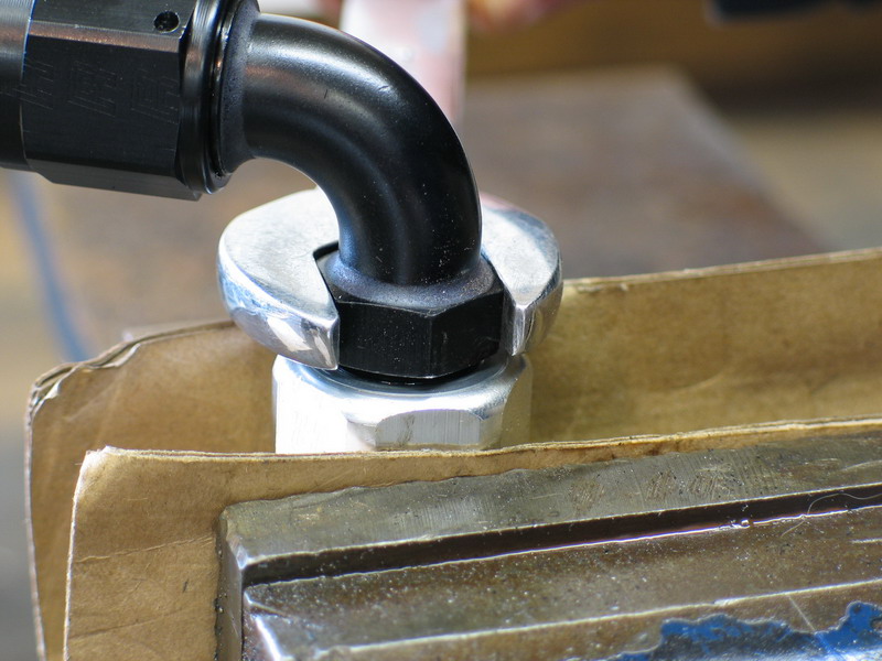 |
As you finish tightening, observe the gap between the hex on the nipple and the socket. | ||||||||||||||||||||||||||||||||||||||||||||||||||||||||||||||||||||||||||||||||||||||||||||||||||||||||||||||||||||||||||||||||||||||||||||||||||||||||||||||||||||||||||||||||||||||||||||||||||||||||||||||||||||||||||||||||||||||||||||||||||||||||||||||||||||||||||||||||||||||||||||||||||||||||||||||||||||||||||||||||||||||||||||||||||||||||||||||||||||||||||||||||||||||||||||||||||||||||||||||||||||||||||||||||||||||||||||||||||||||||||||||||||||||||||||||||||||||||||||||||||||||||||||||||||||||||||||||||||||||||||||||||||||||||||||||||||||||||||||||||||||||||||||||||||||||||||||||||||||||||||||||||||||||||||||||||||||||||||||||||||||||||||||||||||||||||||||||||||||||||||||||||||||||||||||||||||||||||||||||||||||||||||||||||||||||||||||||||||||||||||||||||||||||||||||||||||||||||||||||||||||||||||||||||||||||||||||||||||||||||||||||||||||||||||||||||||||||||||||||||||||||||||||||||||||||||||||||||||||||||||||||||||||||||||||||||||||||||||||||||||||||||||||||||||||||||||||||||||||||
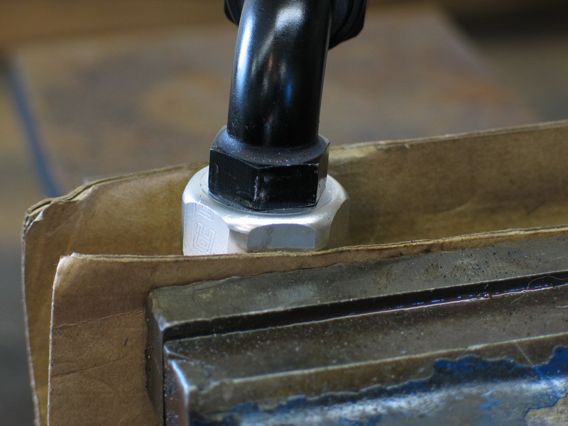 |
On completion, the gap should be no more than 1/16". The nipple may touch the socket, but do not tighten any further than this. An important note here: If you are assembling a hose assembly and neither hose-end is straight nor a swivel design, when you tighten the second nipple into its socket, you must align it with the other hose-end at this time. This is because you must not twist the hose when it is installed in the vehicle, and if neither hose-end is a swivel design, and both hose-ends are angled, there is no other way to align the ends other than with the position of the second nipple in its socket. Fortunately, the 1/16" max gap spec allows for this. That said, this is an area where having at least one swivel hose-end on each hose assembly can enormously simplify hose assembly construction and installation. |
||||||||||||||||||||||||||||||||||||||||||||||||||||||||||||||||||||||||||||||||||||||||||||||||||||||||||||||||||||||||||||||||||||||||||||||||||||||||||||||||||||||||||||||||||||||||||||||||||||||||||||||||||||||||||||||||||||||||||||||||||||||||||||||||||||||||||||||||||||||||||||||||||||||||||||||||||||||||||||||||||||||||||||||||||||||||||||||||||||||||||||||||||||||||||||||||||||||||||||||||||||||||||||||||||||||||||||||||||||||||||||||||||||||||||||||||||||||||||||||||||||||||||||||||||||||||||||||||||||||||||||||||||||||||||||||||||||||||||||||||||||||||||||||||||||||||||||||||||||||||||||||||||||||||||||||||||||||||||||||||||||||||||||||||||||||||||||||||||||||||||||||||||||||||||||||||||||||||||||||||||||||||||||||||||||||||||||||||||||||||||||||||||||||||||||||||||||||||||||||||||||||||||||||||||||||||||||||||||||||||||||||||||||||||||||||||||||||||||||||||||||||||||||||||||||||||||||||||||||||||||||||||||||||||||||||||||||||||||||||||||||||||||||||||||||||||||||||||||||||
 |
With the assembly completed, re-check the alignment mark you made on the hose earlier to ensure the hose hasn't been pushed out of the socket by the nipple being screwed in. If it has, you will have to disassemble and start again. |
||||||||||||||||||||||||||||||||||||||||||||||||||||||||||||||||||||||||||||||||||||||||||||||||||||||||||||||||||||||||||||||||||||||||||||||||||||||||||||||||||||||||||||||||||||||||||||||||||||||||||||||||||||||||||||||||||||||||||||||||||||||||||||||||||||||||||||||||||||||||||||||||||||||||||||||||||||||||||||||||||||||||||||||||||||||||||||||||||||||||||||||||||||||||||||||||||||||||||||||||||||||||||||||||||||||||||||||||||||||||||||||||||||||||||||||||||||||||||||||||||||||||||||||||||||||||||||||||||||||||||||||||||||||||||||||||||||||||||||||||||||||||||||||||||||||||||||||||||||||||||||||||||||||||||||||||||||||||||||||||||||||||||||||||||||||||||||||||||||||||||||||||||||||||||||||||||||||||||||||||||||||||||||||||||||||||||||||||||||||||||||||||||||||||||||||||||||||||||||||||||||||||||||||||||||||||||||||||||||||||||||||||||||||||||||||||||||||||||||||||||||||||||||||||||||||||||||||||||||||||||||||||||||||||||||||||||||||||||||||||||||||||||||||||||||||||||||||||||||||
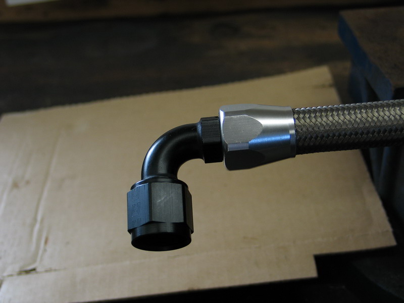 |
The completed hose-end should look like this. Note the bad-ass look achieved with the combination of the Proflex Hose and ProClassic black/clear hose-ends! Before being put into service, the hose assembly should be thoroughly cleaned / blown out and inspected. |
||||||||||||||||||||||||||||||||||||||||||||||||||||||||||||||||||||||||||||||||||||||||||||||||||||||||||||||||||||||||||||||||||||||||||||||||||||||||||||||||||||||||||||||||||||||||||||||||||||||||||||||||||||||||||||||||||||||||||||||||||||||||||||||||||||||||||||||||||||||||||||||||||||||||||||||||||||||||||||||||||||||||||||||||||||||||||||||||||||||||||||||||||||||||||||||||||||||||||||||||||||||||||||||||||||||||||||||||||||||||||||||||||||||||||||||||||||||||||||||||||||||||||||||||||||||||||||||||||||||||||||||||||||||||||||||||||||||||||||||||||||||||||||||||||||||||||||||||||||||||||||||||||||||||||||||||||||||||||||||||||||||||||||||||||||||||||||||||||||||||||||||||||||||||||||||||||||||||||||||||||||||||||||||||||||||||||||||||||||||||||||||||||||||||||||||||||||||||||||||||||||||||||||||||||||||||||||||||||||||||||||||||||||||||||||||||||||||||||||||||||||||||||||||||||||||||||||||||||||||||||||||||||||||||||||||||||||||||||||||||||||||||||||||||||||||||||||||||||||||
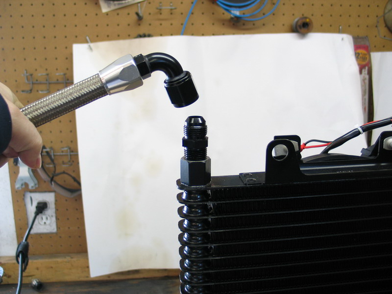 |
The completed hose assembly is very easily installed in the vehicle - one of the many beauties of AN style hose-ends. Simply place the female hose-end on the adapter... |
||||||||||||||||||||||||||||||||||||||||||||||||||||||||||||||||||||||||||||||||||||||||||||||||||||||||||||||||||||||||||||||||||||||||||||||||||||||||||||||||||||||||||||||||||||||||||||||||||||||||||||||||||||||||||||||||||||||||||||||||||||||||||||||||||||||||||||||||||||||||||||||||||||||||||||||||||||||||||||||||||||||||||||||||||||||||||||||||||||||||||||||||||||||||||||||||||||||||||||||||||||||||||||||||||||||||||||||||||||||||||||||||||||||||||||||||||||||||||||||||||||||||||||||||||||||||||||||||||||||||||||||||||||||||||||||||||||||||||||||||||||||||||||||||||||||||||||||||||||||||||||||||||||||||||||||||||||||||||||||||||||||||||||||||||||||||||||||||||||||||||||||||||||||||||||||||||||||||||||||||||||||||||||||||||||||||||||||||||||||||||||||||||||||||||||||||||||||||||||||||||||||||||||||||||||||||||||||||||||||||||||||||||||||||||||||||||||||||||||||||||||||||||||||||||||||||||||||||||||||||||||||||||||||||||||||||||||||||||||||||||||||||||||||||||||||||||||||||||||||
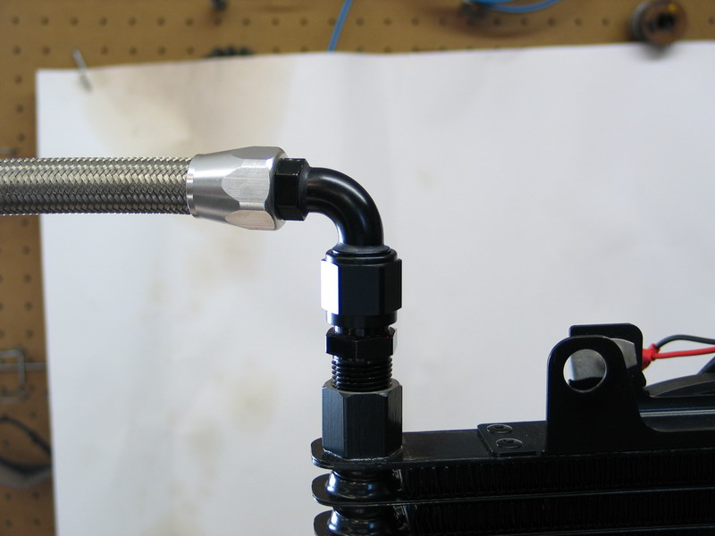 |
... start the threads of the hose-end nut, align the hose, hold the hose in position, and then finish tightening the hose-end nut. Note again, the cool colour combination of black and silver fittings with black components (in this case an oil cooler), and silver stainless-steel hose! |
||||||||||||||||||||||||||||||||||||||||||||||||||||||||||||||||||||||||||||||||||||||||||||||||||||||||||||||||||||||||||||||||||||||||||||||||||||||||||||||||||||||||||||||||||||||||||||||||||||||||||||||||||||||||||||||||||||||||||||||||||||||||||||||||||||||||||||||||||||||||||||||||||||||||||||||||||||||||||||||||||||||||||||||||||||||||||||||||||||||||||||||||||||||||||||||||||||||||||||||||||||||||||||||||||||||||||||||||||||||||||||||||||||||||||||||||||||||||||||||||||||||||||||||||||||||||||||||||||||||||||||||||||||||||||||||||||||||||||||||||||||||||||||||||||||||||||||||||||||||||||||||||||||||||||||||||||||||||||||||||||||||||||||||||||||||||||||||||||||||||||||||||||||||||||||||||||||||||||||||||||||||||||||||||||||||||||||||||||||||||||||||||||||||||||||||||||||||||||||||||||||||||||||||||||||||||||||||||||||||||||||||||||||||||||||||||||||||||||||||||||||||||||||||||||||||||||||||||||||||||||||||||||||||||||||||||||||||||||||||||||||||||||||||||||||||||||||||||||||||
Plumbing System Layout & Installation ProceduresThe following points are offered as some guidance on procedures and considerations for designing, laying out, and installing a plumbing system. Many of the points are paraphrased from the SAE paper: "Selection, installation and maintenance of hose and assemblies — SAE J1273 October 1996" Routing: Attention must be given to optimum hose routing to minimize potential problems (kinking or flow restriction due to hose collapse, twisting of the hose, proximity to hot objects or heat sources). Care must be taken to protect hose from wear, snagging, kinking, bending smaller that minimum bend radius, and cutting - any of which can cause premature hose failure. Any hose that has been kinked or bent to a radius smaller than the minimum bend radius, and any hose that has been cut or is cracked or is otherwise damaged, should be removed and discarded. The hose assembly should be routed in such a manner that if a failure does occur, the escaping fluid will not cause personal injury or equipment damage. In addition, routing should be such that it minimizes the chance that hose failure could cause fluid to come in contact with hot surfaces, open flame, or sparks, as a fire or explosion may otherwise result. Hose installation: Hose should not be twisted or put in torsion either during the installation or while in service. Sharp or excessive bends may cause the hose to kink or rupture. Be sure to allow enough slack to provide for changes in length which will occur when pressure is applied. This change in length can vary from +2% to -4%. Design the installation so the hose assembly is accessible for inspection and easy removal. Bend radius is important. If you do not have a published spec for your hose, a good working rule is that the minimum bend radius should be five or more times the O.D. of the hose. Length: When establishing a proper hose length, motion absorption, hose length changes due to pressure, and hose and machine tolerances and movement must be considered. Hose Cleanliness: During construction and test fitting, it is easy for hose assemblies to become contaminated with dirt and debris. Care must be taken to insure that prior to installation hose assemblies are adequately clean for the application. Radiant Heat: Hose installation and routing must be such that the hose cannot be heated to a point where it becomes damaged or destroyed by nearby heat sources such as as hot manifolds. This can happen even without direct contact and despite the presence of cool air around the hose. Pre-Installation Inspection: Prior to installation, a careful examination of the hose and fittings must be performed. All components must be checked for correct style, size, and length. The hose must be examined for cleanliness, obstructions, blisters, cover looseness, kinks, cracks, cuts or any other visible defects. Inspect the fitting and sealing surfaces for burrs, nicks, corrosion or other imperfections. Do not use any component that displays any signs of nonconformance. Minimum Bend Radius: Installation of a hose at less than the minimum listed bend radius may significantly reduce the hose life. Particular attention must be given to preclude sharp bending at the hose to hose-end juncture. Any bending during installation at less than the minimum bend radius must be avoided. Twist Angle and Orientation: Hose assembly installation must be such that relative motion of machine components does not produce twisting. Securement: In many applications, it may be necessary to restrain, protect, or guide the hose to protect it from damage by unnecessary flexing, pressure surges, and contact with other mechanical components. Care must be taken to ensure such restraints do not introduce additional stress or wear points. Mechanical Loads: External forces can significantly reduce hose life or cause failure. Mechanical loads which must be considered include excessive flexing, twist, kinking, tensile or side loads, bend radius, and vibration. Use of swivel type fittings or adapters may be required to insure no twist is put into the hose. Some applications, such as plumbing lines secured to long-travel suspension components, may require special testing prior to hose selection and use. Mix ‘n’ Match: It is unwise at best, often unacceptable, and quite possibly dangerous to mix ‘n’ match hose and fittings from different manufacturers. Often each manufacturer will have its own proprietary methods of construction and assembly. Some are compatible with others and some are not. The best bet is to use quality hose and fittings from a single manufacturer. Reliable, quality companies like Russell Performance make this easy by a) manufacturing a wide variety of hose and fittings and b) clearly stating in their literature which fittings and hose are designed to be used together. This is particularly true if you are crimping or swaging fittings onto hose – each crimping machine will use particular dies designed for particular fittings. Using an inappropriate combination invites failure and the associated dangers of hose assembly failure. System Checkout: Prior to operational use, all air must be eliminated and the system pressurized to the maximum system pressure (at or below the hose maximum working pressure) and checked for proper function and freedom from leaks. Personnel must stay out of potential hazardous areas during testing. |
|||||||||||||||||||||||||||||||||||||||||||||||||||||||||||||||||||||||||||||||||||||||||||||||||||||||||||||||||||||||||||||||||||||||||||||||||||||||||||||||||||||||||||||||||||||||||||||||||||||||||||||||||||||||||||||||||||||||||||||||||||||||||||||||||||||||||||||||||||||||||||||||||||||||||||||||||||||||||||||||||||||||||||||||||||||||||||||||||||||||||||||||||||||||||||||||||||||||||||||||||||||||||||||||||||||||||||||||||||||||||||||||||||||||||||||||||||||||||||||||||||||||||||||||||||||||||||||||||||||||||||||||||||||||||||||||||||||||||||||||||||||||||||||||||||||||||||||||||||||||||||||||||||||||||||||||||||||||||||||||||||||||||||||||||||||||||||||||||||||||||||||||||||||||||||||||||||||||||||||||||||||||||||||||||||||||||||||||||||||||||||||||||||||||||||||||||||||||||||||||||||||||||||||||||||||||||||||||||||||||||||||||||||||||||||||||||||||||||||||||||||||||||||||||||||||||||||||||||||||||||||||||||||||||||||||||||||||||||||||||||||||||||||||||||||||||||||||||||||||||
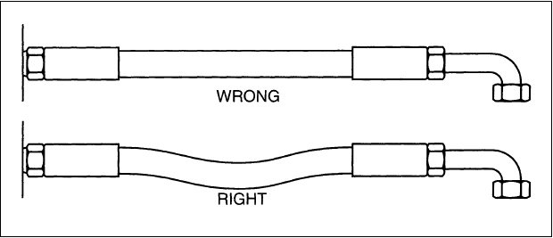 |
When hose installation is straight, allow enough slack in hose line to provide for length changes which will occur when pressure is applied. This change in length can vary from +2% to -4%. | ||||||||||||||||||||||||||||||||||||||||||||||||||||||||||||||||||||||||||||||||||||||||||||||||||||||||||||||||||||||||||||||||||||||||||||||||||||||||||||||||||||||||||||||||||||||||||||||||||||||||||||||||||||||||||||||||||||||||||||||||||||||||||||||||||||||||||||||||||||||||||||||||||||||||||||||||||||||||||||||||||||||||||||||||||||||||||||||||||||||||||||||||||||||||||||||||||||||||||||||||||||||||||||||||||||||||||||||||||||||||||||||||||||||||||||||||||||||||||||||||||||||||||||||||||||||||||||||||||||||||||||||||||||||||||||||||||||||||||||||||||||||||||||||||||||||||||||||||||||||||||||||||||||||||||||||||||||||||||||||||||||||||||||||||||||||||||||||||||||||||||||||||||||||||||||||||||||||||||||||||||||||||||||||||||||||||||||||||||||||||||||||||||||||||||||||||||||||||||||||||||||||||||||||||||||||||||||||||||||||||||||||||||||||||||||||||||||||||||||||||||||||||||||||||||||||||||||||||||||||||||||||||||||||||||||||||||||||||||||||||||||||||||||||||||||||||||||||||||||||
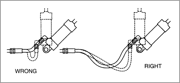 |
Adequate hose length is necessary to accommodate relative movement between components and to avoid abrasion. | ||||||||||||||||||||||||||||||||||||||||||||||||||||||||||||||||||||||||||||||||||||||||||||||||||||||||||||||||||||||||||||||||||||||||||||||||||||||||||||||||||||||||||||||||||||||||||||||||||||||||||||||||||||||||||||||||||||||||||||||||||||||||||||||||||||||||||||||||||||||||||||||||||||||||||||||||||||||||||||||||||||||||||||||||||||||||||||||||||||||||||||||||||||||||||||||||||||||||||||||||||||||||||||||||||||||||||||||||||||||||||||||||||||||||||||||||||||||||||||||||||||||||||||||||||||||||||||||||||||||||||||||||||||||||||||||||||||||||||||||||||||||||||||||||||||||||||||||||||||||||||||||||||||||||||||||||||||||||||||||||||||||||||||||||||||||||||||||||||||||||||||||||||||||||||||||||||||||||||||||||||||||||||||||||||||||||||||||||||||||||||||||||||||||||||||||||||||||||||||||||||||||||||||||||||||||||||||||||||||||||||||||||||||||||||||||||||||||||||||||||||||||||||||||||||||||||||||||||||||||||||||||||||||||||||||||||||||||||||||||||||||||||||||||||||||||||||||||||||||||
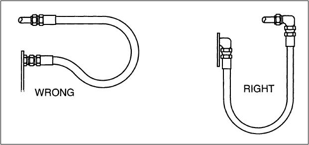 |
When two fittings that are to be joined by a hose are in close proximity, use an angle adapter to avoid having to bend the hose in a tight radius that is less than the the minimum bend radius of the hose. | ||||||||||||||||||||||||||||||||||||||||||||||||||||||||||||||||||||||||||||||||||||||||||||||||||||||||||||||||||||||||||||||||||||||||||||||||||||||||||||||||||||||||||||||||||||||||||||||||||||||||||||||||||||||||||||||||||||||||||||||||||||||||||||||||||||||||||||||||||||||||||||||||||||||||||||||||||||||||||||||||||||||||||||||||||||||||||||||||||||||||||||||||||||||||||||||||||||||||||||||||||||||||||||||||||||||||||||||||||||||||||||||||||||||||||||||||||||||||||||||||||||||||||||||||||||||||||||||||||||||||||||||||||||||||||||||||||||||||||||||||||||||||||||||||||||||||||||||||||||||||||||||||||||||||||||||||||||||||||||||||||||||||||||||||||||||||||||||||||||||||||||||||||||||||||||||||||||||||||||||||||||||||||||||||||||||||||||||||||||||||||||||||||||||||||||||||||||||||||||||||||||||||||||||||||||||||||||||||||||||||||||||||||||||||||||||||||||||||||||||||||||||||||||||||||||||||||||||||||||||||||||||||||||||||||||||||||||||||||||||||||||||||||||||||||||||||||||||||||||||
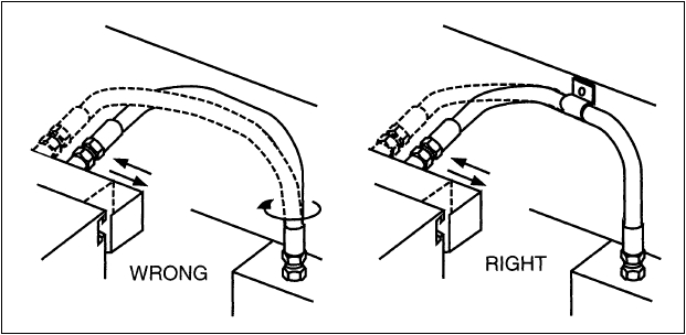 |
When a hose connects components that move in relation to each other and the hose changes direction in more than one plane, avoid twisting of hose by clamping hose at change of plane. | ||||||||||||||||||||||||||||||||||||||||||||||||||||||||||||||||||||||||||||||||||||||||||||||||||||||||||||||||||||||||||||||||||||||||||||||||||||||||||||||||||||||||||||||||||||||||||||||||||||||||||||||||||||||||||||||||||||||||||||||||||||||||||||||||||||||||||||||||||||||||||||||||||||||||||||||||||||||||||||||||||||||||||||||||||||||||||||||||||||||||||||||||||||||||||||||||||||||||||||||||||||||||||||||||||||||||||||||||||||||||||||||||||||||||||||||||||||||||||||||||||||||||||||||||||||||||||||||||||||||||||||||||||||||||||||||||||||||||||||||||||||||||||||||||||||||||||||||||||||||||||||||||||||||||||||||||||||||||||||||||||||||||||||||||||||||||||||||||||||||||||||||||||||||||||||||||||||||||||||||||||||||||||||||||||||||||||||||||||||||||||||||||||||||||||||||||||||||||||||||||||||||||||||||||||||||||||||||||||||||||||||||||||||||||||||||||||||||||||||||||||||||||||||||||||||||||||||||||||||||||||||||||||||||||||||||||||||||||||||||||||||||||||||||||||||||||||||||||||||||
 |
Use proper angle adaptors to avoid sharp twists or bends in hose. When determining the length of hose assemblies, provide sufficient length to prevent bending strain from localizing at the back of the hose-end. |
||||||||||||||||||||||||||||||||||||||||||||||||||||||||||||||||||||||||||||||||||||||||||||||||||||||||||||||||||||||||||||||||||||||||||||||||||||||||||||||||||||||||||||||||||||||||||||||||||||||||||||||||||||||||||||||||||||||||||||||||||||||||||||||||||||||||||||||||||||||||||||||||||||||||||||||||||||||||||||||||||||||||||||||||||||||||||||||||||||||||||||||||||||||||||||||||||||||||||||||||||||||||||||||||||||||||||||||||||||||||||||||||||||||||||||||||||||||||||||||||||||||||||||||||||||||||||||||||||||||||||||||||||||||||||||||||||||||||||||||||||||||||||||||||||||||||||||||||||||||||||||||||||||||||||||||||||||||||||||||||||||||||||||||||||||||||||||||||||||||||||||||||||||||||||||||||||||||||||||||||||||||||||||||||||||||||||||||||||||||||||||||||||||||||||||||||||||||||||||||||||||||||||||||||||||||||||||||||||||||||||||||||||||||||||||||||||||||||||||||||||||||||||||||||||||||||||||||||||||||||||||||||||||||||||||||||||||||||||||||||||||||||||||||||||||||||||||||||||||||
 |
When there is relative motion between two parts joined by a hose, prevent twisting and distortion of hose by routing it in a gentle bend in same plane as the motion of the moving part to which hose is connected. | ||||||||||||||||||||||||||||||||||||||||||||||||||||||||||||||||||||||||||||||||||||||||||||||||||||||||||||||||||||||||||||||||||||||||||||||||||||||||||||||||||||||||||||||||||||||||||||||||||||||||||||||||||||||||||||||||||||||||||||||||||||||||||||||||||||||||||||||||||||||||||||||||||||||||||||||||||||||||||||||||||||||||||||||||||||||||||||||||||||||||||||||||||||||||||||||||||||||||||||||||||||||||||||||||||||||||||||||||||||||||||||||||||||||||||||||||||||||||||||||||||||||||||||||||||||||||||||||||||||||||||||||||||||||||||||||||||||||||||||||||||||||||||||||||||||||||||||||||||||||||||||||||||||||||||||||||||||||||||||||||||||||||||||||||||||||||||||||||||||||||||||||||||||||||||||||||||||||||||||||||||||||||||||||||||||||||||||||||||||||||||||||||||||||||||||||||||||||||||||||||||||||||||||||||||||||||||||||||||||||||||||||||||||||||||||||||||||||||||||||||||||||||||||||||||||||||||||||||||||||||||||||||||||||||||||||||||||||||||||||||||||||||||||||||||||||||||||||||||||||
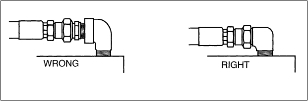 |
Reduce number of joints and potential leak paths by using proper adaptors. | ||||||||||||||||||||||||||||||||||||||||||||||||||||||||||||||||||||||||||||||||||||||||||||||||||||||||||||||||||||||||||||||||||||||||||||||||||||||||||||||||||||||||||||||||||||||||||||||||||||||||||||||||||||||||||||||||||||||||||||||||||||||||||||||||||||||||||||||||||||||||||||||||||||||||||||||||||||||||||||||||||||||||||||||||||||||||||||||||||||||||||||||||||||||||||||||||||||||||||||||||||||||||||||||||||||||||||||||||||||||||||||||||||||||||||||||||||||||||||||||||||||||||||||||||||||||||||||||||||||||||||||||||||||||||||||||||||||||||||||||||||||||||||||||||||||||||||||||||||||||||||||||||||||||||||||||||||||||||||||||||||||||||||||||||||||||||||||||||||||||||||||||||||||||||||||||||||||||||||||||||||||||||||||||||||||||||||||||||||||||||||||||||||||||||||||||||||||||||||||||||||||||||||||||||||||||||||||||||||||||||||||||||||||||||||||||||||||||||||||||||||||||||||||||||||||||||||||||||||||||||||||||||||||||||||||||||||||||||||||||||||||||||||||||||||||||||||||||||||||||
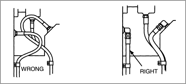 |
Route hose as directly as possible by using 45°, 90°, and other angled adaptors and fittings. Avoid using excessive hose length. | ||||||||||||||||||||||||||||||||||||||||||||||||||||||||||||||||||||||||||||||||||||||||||||||||||||||||||||||||||||||||||||||||||||||||||||||||||||||||||||||||||||||||||||||||||||||||||||||||||||||||||||||||||||||||||||||||||||||||||||||||||||||||||||||||||||||||||||||||||||||||||||||||||||||||||||||||||||||||||||||||||||||||||||||||||||||||||||||||||||||||||||||||||||||||||||||||||||||||||||||||||||||||||||||||||||||||||||||||||||||||||||||||||||||||||||||||||||||||||||||||||||||||||||||||||||||||||||||||||||||||||||||||||||||||||||||||||||||||||||||||||||||||||||||||||||||||||||||||||||||||||||||||||||||||||||||||||||||||||||||||||||||||||||||||||||||||||||||||||||||||||||||||||||||||||||||||||||||||||||||||||||||||||||||||||||||||||||||||||||||||||||||||||||||||||||||||||||||||||||||||||||||||||||||||||||||||||||||||||||||||||||||||||||||||||||||||||||||||||||||||||||||||||||||||||||||||||||||||||||||||||||||||||||||||||||||||||||||||||||||||||||||||||||||||||||||||||||||||||||||
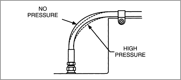 |
To allow for length changes when hose is pressurized, do not clamp at bends. Curves will absorb changes. Do not clamp high and low pressure lines together. | ||||||||||||||||||||||||||||||||||||||||||||||||||||||||||||||||||||||||||||||||||||||||||||||||||||||||||||||||||||||||||||||||||||||||||||||||||||||||||||||||||||||||||||||||||||||||||||||||||||||||||||||||||||||||||||||||||||||||||||||||||||||||||||||||||||||||||||||||||||||||||||||||||||||||||||||||||||||||||||||||||||||||||||||||||||||||||||||||||||||||||||||||||||||||||||||||||||||||||||||||||||||||||||||||||||||||||||||||||||||||||||||||||||||||||||||||||||||||||||||||||||||||||||||||||||||||||||||||||||||||||||||||||||||||||||||||||||||||||||||||||||||||||||||||||||||||||||||||||||||||||||||||||||||||||||||||||||||||||||||||||||||||||||||||||||||||||||||||||||||||||||||||||||||||||||||||||||||||||||||||||||||||||||||||||||||||||||||||||||||||||||||||||||||||||||||||||||||||||||||||||||||||||||||||||||||||||||||||||||||||||||||||||||||||||||||||||||||||||||||||||||||||||||||||||||||||||||||||||||||||||||||||||||||||||||||||||||||||||||||||||||||||||||||||||||||||||||||||||||||
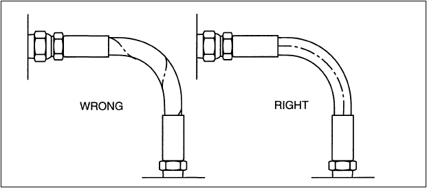 |
When installing hose, make sure it is not twisted. Pressure applied to a twisted hose can result in hose failure or loosening of fittings. | ||||||||||||||||||||||||||||||||||||||||||||||||||||||||||||||||||||||||||||||||||||||||||||||||||||||||||||||||||||||||||||||||||||||||||||||||||||||||||||||||||||||||||||||||||||||||||||||||||||||||||||||||||||||||||||||||||||||||||||||||||||||||||||||||||||||||||||||||||||||||||||||||||||||||||||||||||||||||||||||||||||||||||||||||||||||||||||||||||||||||||||||||||||||||||||||||||||||||||||||||||||||||||||||||||||||||||||||||||||||||||||||||||||||||||||||||||||||||||||||||||||||||||||||||||||||||||||||||||||||||||||||||||||||||||||||||||||||||||||||||||||||||||||||||||||||||||||||||||||||||||||||||||||||||||||||||||||||||||||||||||||||||||||||||||||||||||||||||||||||||||||||||||||||||||||||||||||||||||||||||||||||||||||||||||||||||||||||||||||||||||||||||||||||||||||||||||||||||||||||||||||||||||||||||||||||||||||||||||||||||||||||||||||||||||||||||||||||||||||||||||||||||||||||||||||||||||||||||||||||||||||||||||||||||||||||||||||||||||||||||||||||||||||||||||||||||||||||||||||||
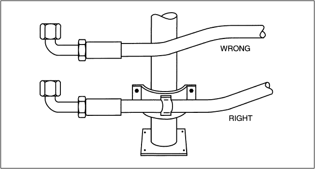 |
High ambient temperatures shorten hose life so make sure hose is kept away from hot parts. If this is not possible, insulate hose. | ||||||||||||||||||||||||||||||||||||||||||||||||||||||||||||||||||||||||||||||||||||||||||||||||||||||||||||||||||||||||||||||||||||||||||||||||||||||||||||||||||||||||||||||||||||||||||||||||||||||||||||||||||||||||||||||||||||||||||||||||||||||||||||||||||||||||||||||||||||||||||||||||||||||||||||||||||||||||||||||||||||||||||||||||||||||||||||||||||||||||||||||||||||||||||||||||||||||||||||||||||||||||||||||||||||||||||||||||||||||||||||||||||||||||||||||||||||||||||||||||||||||||||||||||||||||||||||||||||||||||||||||||||||||||||||||||||||||||||||||||||||||||||||||||||||||||||||||||||||||||||||||||||||||||||||||||||||||||||||||||||||||||||||||||||||||||||||||||||||||||||||||||||||||||||||||||||||||||||||||||||||||||||||||||||||||||||||||||||||||||||||||||||||||||||||||||||||||||||||||||||||||||||||||||||||||||||||||||||||||||||||||||||||||||||||||||||||||||||||||||||||||||||||||||||||||||||||||||||||||||||||||||||||||||||||||||||||||||||||||||||||||||||||||||||||||||||||||||||||||
 |
Elbows and adaptors should be used to relieve strain on hose assemblies, and to provide neater installations which will be more accessible for inspection and maintenance. | ||||||||||||||||||||||||||||||||||||||||||||||||||||||||||||||||||||||||||||||||||||||||||||||||||||||||||||||||||||||||||||||||||||||||||||||||||||||||||||||||||||||||||||||||||||||||||||||||||||||||||||||||||||||||||||||||||||||||||||||||||||||||||||||||||||||||||||||||||||||||||||||||||||||||||||||||||||||||||||||||||||||||||||||||||||||||||||||||||||||||||||||||||||||||||||||||||||||||||||||||||||||||||||||||||||||||||||||||||||||||||||||||||||||||||||||||||||||||||||||||||||||||||||||||||||||||||||||||||||||||||||||||||||||||||||||||||||||||||||||||||||||||||||||||||||||||||||||||||||||||||||||||||||||||||||||||||||||||||||||||||||||||||||||||||||||||||||||||||||||||||||||||||||||||||||||||||||||||||||||||||||||||||||||||||||||||||||||||||||||||||||||||||||||||||||||||||||||||||||||||||||||||||||||||||||||||||||||||||||||||||||||||||||||||||||||||||||||||||||||||||||||||||||||||||||||||||||||||||||||||||||||||||||||||||||||||||||||||||||||||||||||||||||||||||||||||||||||||||||||
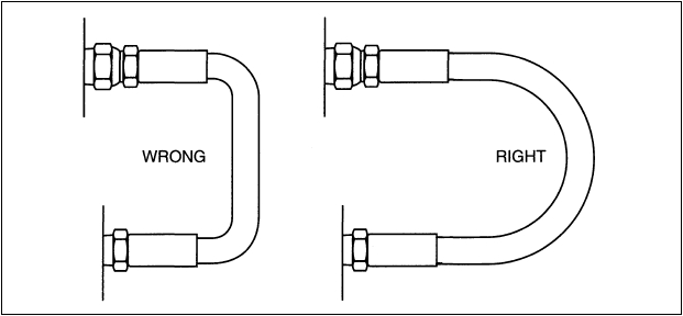 |
To avoid hose collapse and flow restriction, keep hose bend radii as large as possible. Refer to hose specification tables for minimum bend radii. | ||||||||||||||||||||||||||||||||||||||||||||||||||||||||||||||||||||||||||||||||||||||||||||||||||||||||||||||||||||||||||||||||||||||||||||||||||||||||||||||||||||||||||||||||||||||||||||||||||||||||||||||||||||||||||||||||||||||||||||||||||||||||||||||||||||||||||||||||||||||||||||||||||||||||||||||||||||||||||||||||||||||||||||||||||||||||||||||||||||||||||||||||||||||||||||||||||||||||||||||||||||||||||||||||||||||||||||||||||||||||||||||||||||||||||||||||||||||||||||||||||||||||||||||||||||||||||||||||||||||||||||||||||||||||||||||||||||||||||||||||||||||||||||||||||||||||||||||||||||||||||||||||||||||||||||||||||||||||||||||||||||||||||||||||||||||||||||||||||||||||||||||||||||||||||||||||||||||||||||||||||||||||||||||||||||||||||||||||||||||||||||||||||||||||||||||||||||||||||||||||||||||||||||||||||||||||||||||||||||||||||||||||||||||||||||||||||||||||||||||||||||||||||||||||||||||||||||||||||||||||||||||||||||||||||||||||||||||||||||||||||||||||||||||||||||||||||||||||||||||
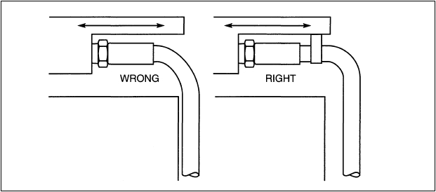 |
Install hose so that it avoids rubbing and abrasion. Often, clamps are required to support long hose runs or to keep hose away from moving parts. Use clamps of the correct size. A clamp too large allows hose to move inside the clamp and causes abrasion. | ||||||||||||||||||||||||||||||||||||||||||||||||||||||||||||||||||||||||||||||||||||||||||||||||||||||||||||||||||||||||||||||||||||||||||||||||||||||||||||||||||||||||||||||||||||||||||||||||||||||||||||||||||||||||||||||||||||||||||||||||||||||||||||||||||||||||||||||||||||||||||||||||||||||||||||||||||||||||||||||||||||||||||||||||||||||||||||||||||||||||||||||||||||||||||||||||||||||||||||||||||||||||||||||||||||||||||||||||||||||||||||||||||||||||||||||||||||||||||||||||||||||||||||||||||||||||||||||||||||||||||||||||||||||||||||||||||||||||||||||||||||||||||||||||||||||||||||||||||||||||||||||||||||||||||||||||||||||||||||||||||||||||||||||||||||||||||||||||||||||||||||||||||||||||||||||||||||||||||||||||||||||||||||||||||||||||||||||||||||||||||||||||||||||||||||||||||||||||||||||||||||||||||||||||||||||||||||||||||||||||||||||||||||||||||||||||||||||||||||||||||||||||||||||||||||||||||||||||||||||||||||||||||||||||||||||||||||||||||||||||||||||||||||||||||||||||||||||||||||||
|
|||||||||||||||||||||||||||||||||||||||||||||||||||||||||||||||||||||||||||||||||||||||||||||||||||||||||||||||||||||||||||||||||||||||||||||||||||||||||||||||||||||||||||||||||||||||||||||||||||||||||||||||||||||||||||||||||||||||||||||||||||||||||||||||||||||||||||||||||||||||||||||||||||||||||||||||||||||||||||||||||||||||||||||||||||||||||||||||||||||||||||||||||||||||||||||||||||||||||||||||||||||||||||||||||||||||||||||||||||||||||||||||||||||||||||||||||||||||||||||||||||||||||||||||||||||||||||||||||||||||||||||||||||||||||||||||||||||||||||||||||||||||||||||||||||||||||||||||||||||||||||||||||||||||||||||||||||||||||||||||||||||||||||||||||||||||||||||||||||||||||||||||||||||||||||||||||||||||||||||||||||||||||||||||||||||||||||||||||||||||||||||||||||||||||||||||||||||||||||||||||||||||||||||||||||||||||||||||||||||||||||||||||||||||||||||||||||||||||||||||||||||||||||||||||||||||||||||||||||||||||||||||||||||||||||||||||||||||||||||||||||||||||||||||||||||||||||||||||||||||

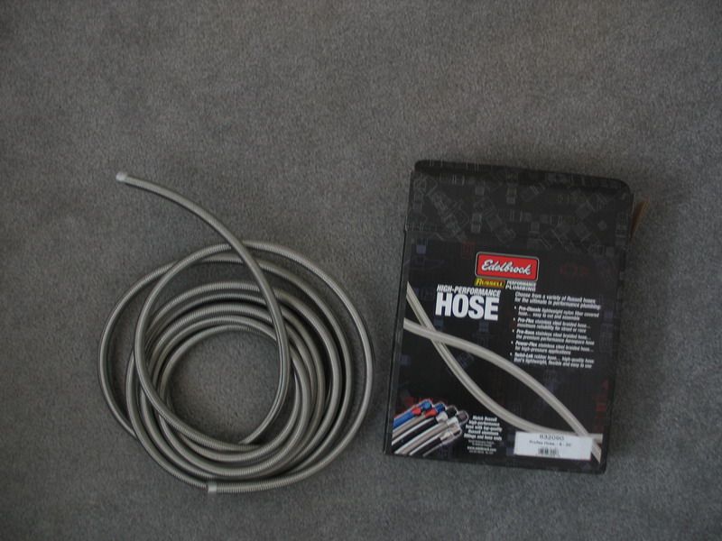
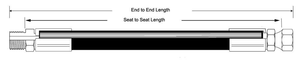
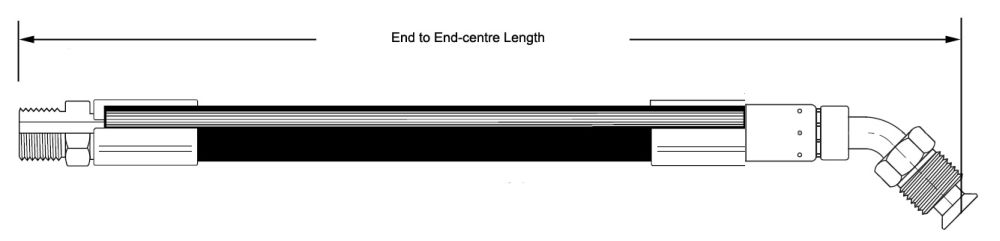
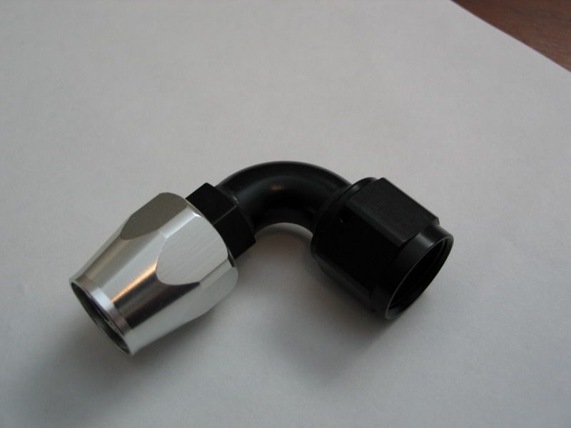
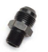
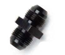
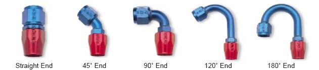
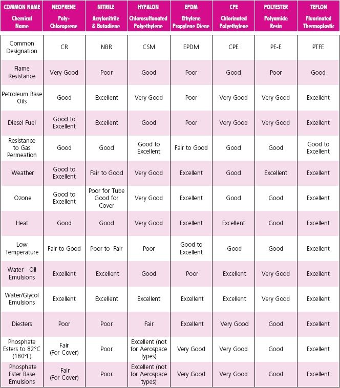
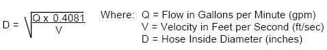
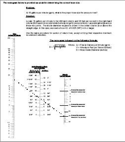
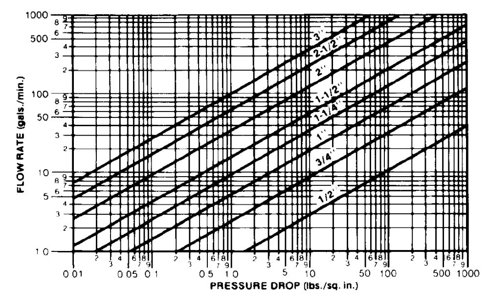
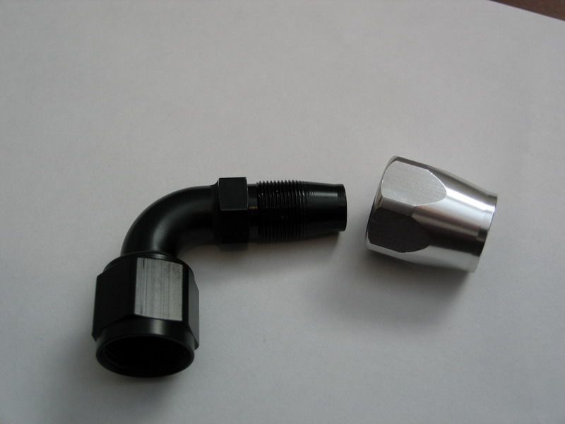
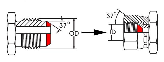
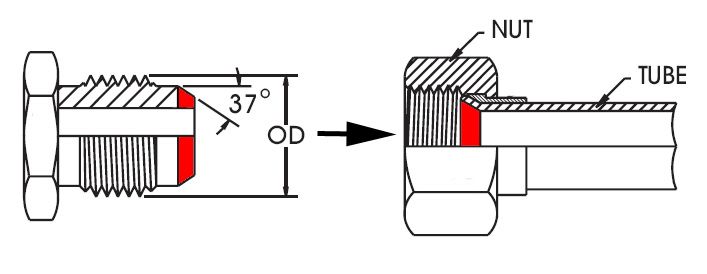
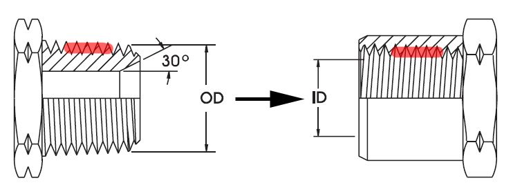
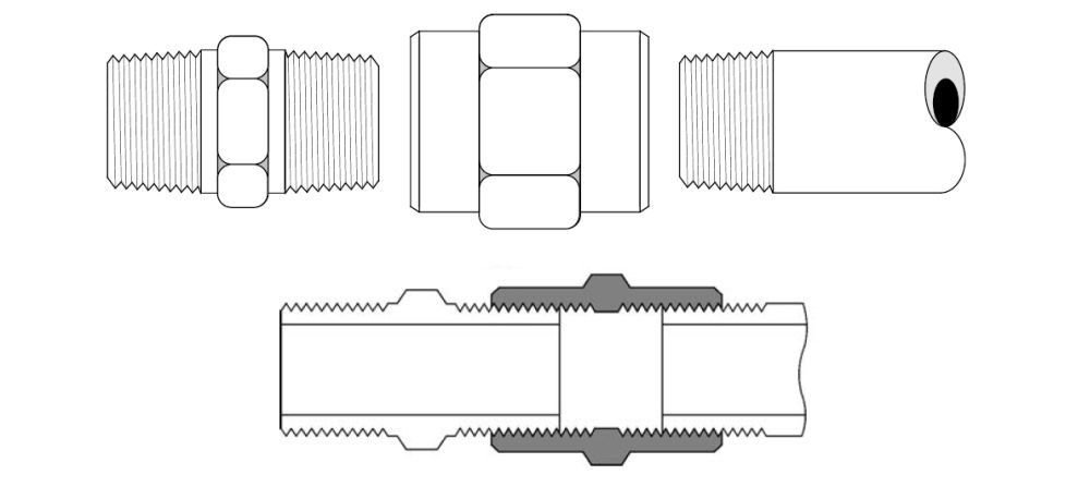
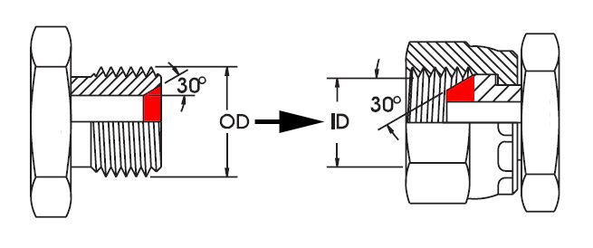

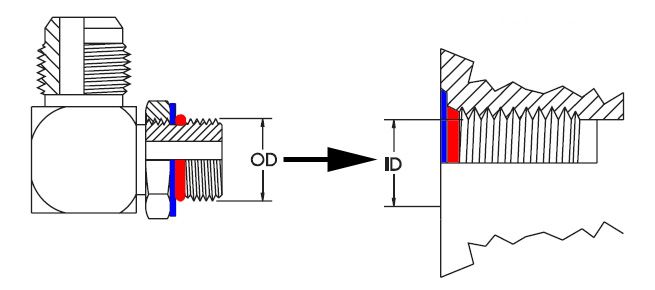
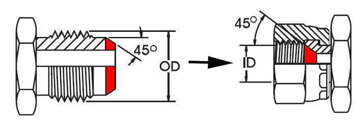
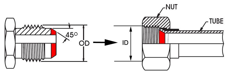
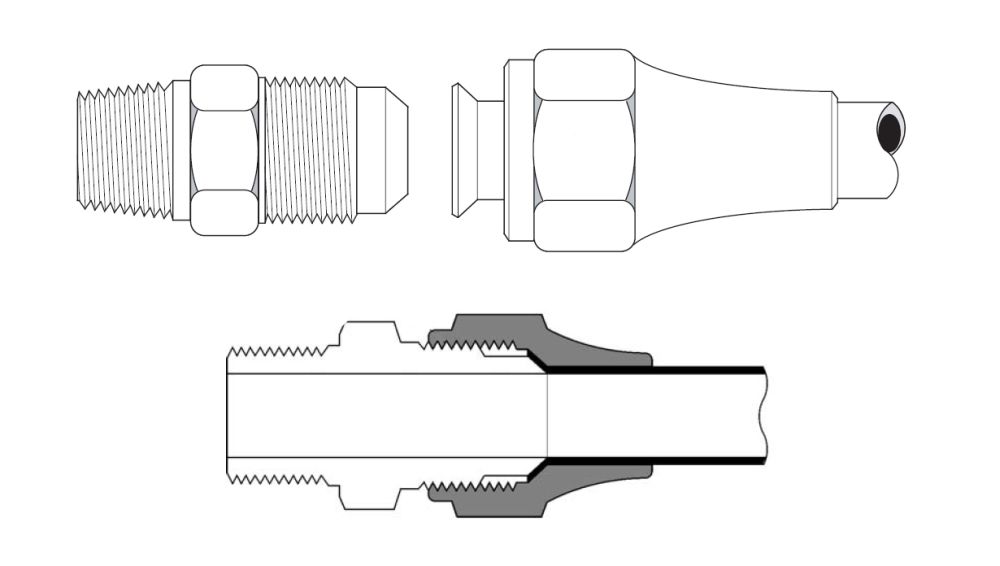
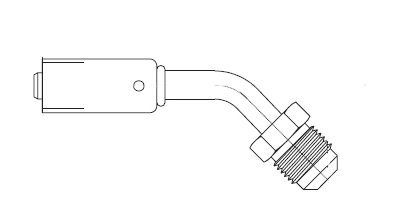
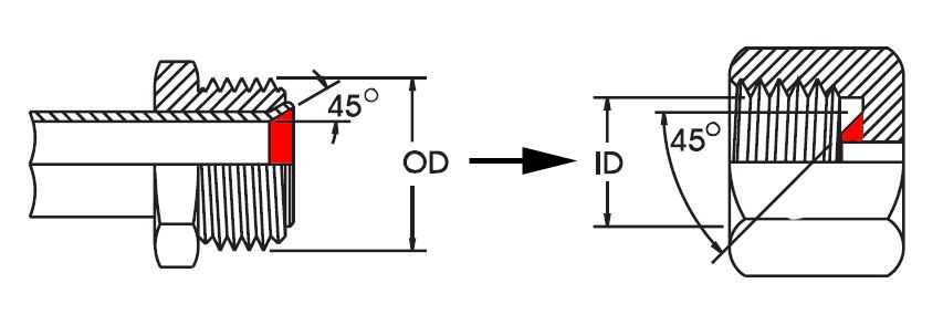
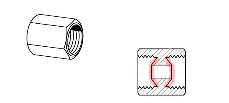
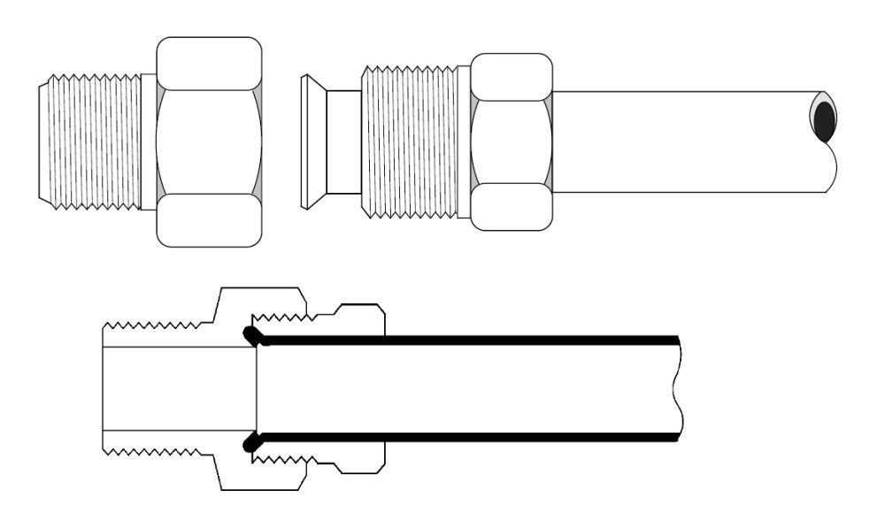
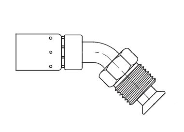
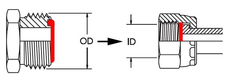
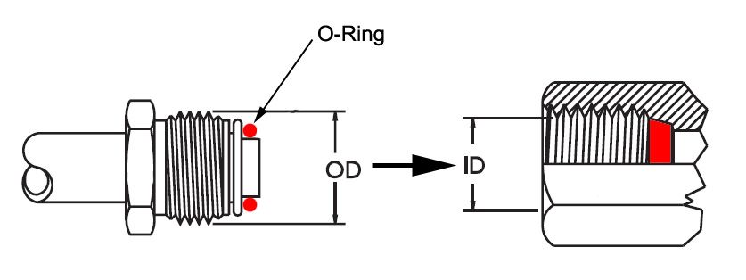
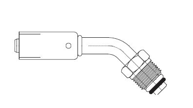
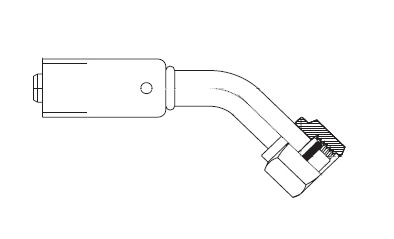
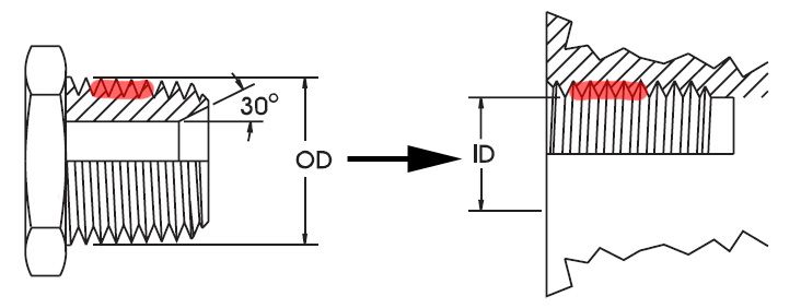
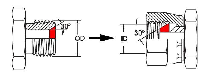
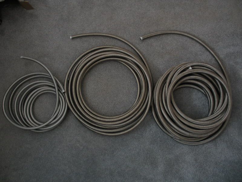
|