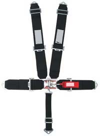
 |
Driver Restraint System Installation
By Anon E. Mouse |
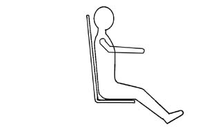 |
Here we have our poor, crash-prone driver sitting happily in his seat. Let's call him Larry. | ||||||||||||||||||||||||||||||||||||||||||||||||||||||||
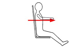 |
When poor Larry's car meets an immovable object at speed, inertia will cause Larry to be thrown forward, as indicated by the red arrow. | ||||||||||||||||||||||||||||||||||||||||||||||||||||||||
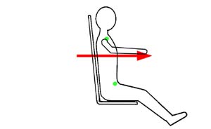 |
In order to prevent Larry from being thrown into the steering wheel and injured, or worse, ejected from the vehicle (God forbid!), he needs to be restrained by the hardpoints in his body that are capable of sustaining the forces involved without causing poor Larry immediate grievous injury. These hardpoints are his pelvic bone and clavicles, as indicated by the green dots. | ||||||||||||||||||||||||||||||||||||||||||||||||||||||||
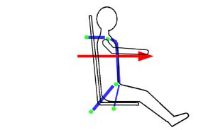 |
We then connect Larry's hardpoints to appropriate hardpoints in the chassis using a properly installed and fitted driver restraint system (harness). Here we can see the shoulder belt, lap belt, and anti-sub belt connected to the car's chassis / cage hardpoints (identified by green dots). In this manner, Larry stands the greatest chance of being restrained during a crash and hopefully avoiding serious injury. | ||||||||||||||||||||||||||||||||||||||||||||||||||||||||
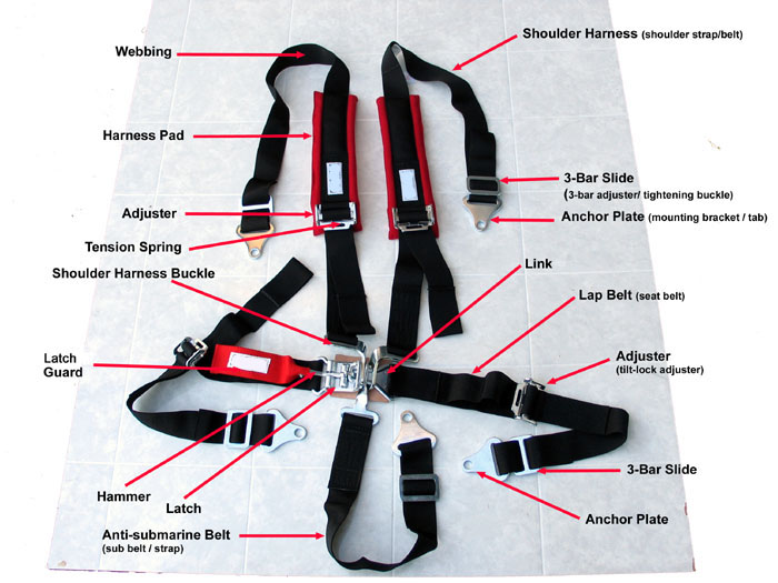
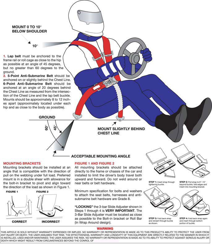
We will return to Larry and his restraint system when we discuss shoulder harness mounting. In order for the driver restraint system to function as a whole and keep the driver inside the roll cage where the least amount of injury will occur during a crash, each individual part must do its job. The shoulder harness is intended to restrain movement of the upper torso. It does this by holding the driver back in his seat. The shoulder harness is not designed to hold the driver down in the seat. An optional sternum strap can be used to connect the belts of the shoulder harness together which helps distribute load between the clavicles and sternum and also may help prevent the driver from slipping out of the shoulder harness. The lap belt is intended to restrain movement of the pelvis and lower torso. It holds the driver back and down in the seat. It must be located and properly tightened so that it rests in the pelvic crest between the pelvic bone and upper thigh. It is also the lap belt that holds the driver down in the seat in a low-speed roll-over - not the shoulder harness. In order to be most effective, the lap belt must be used with an anti-submarine belt to keep it in the proper position. The anti-submarine belt prevents the driver from slipping forward and under the lap belt during a crash. It also holds the harness buckle in place over the pelvic area and keeps the lap belt in the proper location over the pelvic bone. Because the pelvic bone can withstand more force than the abdomen, it is critical that the lap belt be maintained in the proper position. The main buckle, or latching assembly, in a driver restraint connects all the individual belts together providing for quick, easy, and reliable securing of the restraint system as well as providing a quick and simple mechanism for the driver to release the restraints and egress the vehicle in a hurry in the event of fire or some other emergency. Tilt-lock adjusters on the shoulder belts and lap belts provide a method for the driver to quickly and easily tighten and loosen the belts. They also provide a small measure of adjustment to the lengths of the belts which can accommodate different drivers or different clothing. However, if a large adjustment in length is required, this will have to be made at the mounting points or 3-bar slides (if equipped) as the range of adjustment at the tilt-locks is relatively small, especially in the shoulder belts if the harness is to remain positioned properly on the body. In other words, if the restraint is properly installed and adjusted for a 5'4" 140 lb driver, it is very unlikely that it could be properly adjusted for a 6'4" 250 lb driver using only the tilt-lock adjusters. Gross adjustments in the length of the individual belts can be made with a combination of belt length, anchor point location in the vehicle relative to the seat, and the 3-bar slide if so equipped. Finally, all the individual belts must be properly anchored to appropriate chassis hardpoints using proper hardware and methods. Driver Restraint System InstallationThe following diagram is a generic instruction sheet utilized by a number of different manufacturer's and covers the basics of installing a driver restraint system, hereafter referred to as the "install diagram". Let's have a look in a little more detail. Any driver restraint system will only function properly if:
General TipsThe following are general guidelines and tips for restraint installation:
3-bar SlidesRegardless of the mounting style - wrap-around, bolt-in, or snap-in; and regardless of whether the mount in question is for a lap, anti-sub, or shoulder belt, if the belt uses a 3-bar slide there are two critical rules that must be observed in order for the belt to function properly. First, the 3-bar slide MUST be located as close as possible to the anchor plate or bar around which the belt is wrapped. |
|||||||||||||||||||||||||||||||||||||||||||||||||||||||||
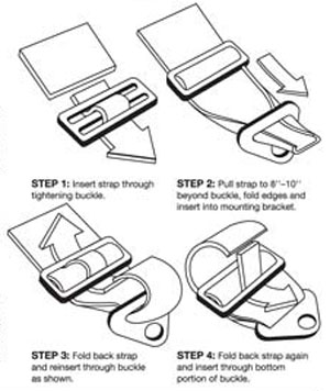 |
Second, the belt MUST be wrapped back a fourth time through the 3-bar slide to prevent the belt from loosening in the slide. The proper method is illustrated in the lower right of the install diagram and repeated here. | ||||||||||||||||||||||||||||||||||||||||||||||||||||||||
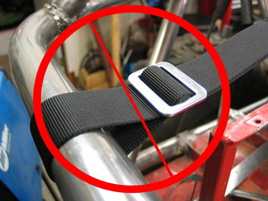 |
FAIL! This wrap-around installation fails on both counts. The 3-bar slide is too far from the bar and the belt is not properly wrapped back through the 3-bar slide. |
||||||||||||||||||||||||||||||||||||||||||||||||||||||||
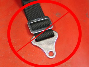 |
FAIL! This bolt-in anchor plate has the 3-bar slide close enough, but the belt is still not wrapped back. |
||||||||||||||||||||||||||||||||||||||||||||||||||||||||
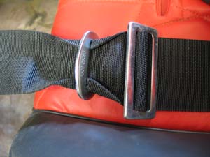 |
Here the belt is threaded through the 3-bar slide and then the anchor plate. Note how, since the belt is 3" wide, the corners of the belt are folded over where it is threaded through the 2" wide slot in the anchor plate. |
||||||||||||||||||||||||||||||||||||||||||||||||||||||||
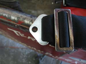 |
The belt is then threaded back through the 3-bar slide... | ||||||||||||||||||||||||||||||||||||||||||||||||||||||||
 |
...and then the belt is wrapped back through the slide. | ||||||||||||||||||||||||||||||||||||||||||||||||||||||||
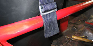 |
Here a wrap-around installation of a 3" belt shows proper placement of the 3-bar slide, close to the bar, and proper wrap-back of the belt. | ||||||||||||||||||||||||||||||||||||||||||||||||||||||||
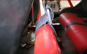 |
Side shot of the same thing. | ||||||||||||||||||||||||||||||||||||||||||||||||||||||||
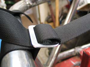 |
A 2" wrap-around installation with proper slide placement and belt wrap-back, although the wrap-back needs to be tightened. | ||||||||||||||||||||||||||||||||||||||||||||||||||||||||
Bolt-in Mount Hardware StrengthAs previously mentioned, the minimum grade for all restraint mounts is SAE Grade 8. The following table may assist you in selecting the appropriate fasteners: Shear Strengths of SAE Gr 8 bolts with yield of 130,000 psi
|
|||||||||||||||||||||||||||||||||||||||||||||||||||||||||
Nominal size (inch) |
Thread (TPI) |
Tensile stress area |
Yield strength (psi) |
Tensile yield |
Shear yield (lbs) @ 60% of tensile. |
Max load (lbs) |
Design factor |
3/8 |
Fine (24) |
.0878 |
130, 000 |
11, 414 |
6848 |
3000 |
2.3 |
|
Coarse (16) |
.0774 |
130, 000 |
10,062 |
6037 |
3000 |
2.0 |
7/16 |
Fine (20) |
.1187 |
130, 000 |
15,431 |
9259 |
3000 |
3.1 |
|
Coarse (14) |
.1063 |
130, 000 |
13,819 |
8291 |
3000 |
2.8 |
1/2 |
Fine (20) |
.1599 |
130, 000 |
20,787 |
12,472 |
3000 |
4.2 |
|
Coarse (13) |
.1419 |
130, 000 |
18,447 |
11,068 |
3000 |
3.7 |
Lap Belt
During a collision the lap belt is normally loaded more than any other belt. Lap belts should never be mounted to the floor or sheet metal, only to the frame / chassis / roll cage.
As shown in the install diagram above, the lap belt is to be installed at an angle between 45° and 60° relative to the ground. This angle allows the lap belt to pull back and down, minimizing occupant movement and also allows the lap belt to counteract the upward pull of the shoulder harness. A lap belt installed at too shallow of an angle (< 45°) will allow the shoulder harness to pull the lap belt up off the pelvic area and into the abdominal region with the likelihood of injury. A lap belt installed at too much of an angle (> 60°) will not adequately restrain the forward movement of the occupant's lower torso / pelvis.
The two mounting brackets for the lap belt anchor plates should normally be mounted no further apart than the width of the occupant’s pelvis or the outer width of the seat. Mounting the brackets further apart than this will increase the load on the belts, resulting in excessive stretching of the webbing during an impact and possibly exceeding the load capacity of the webbing and / or anchor plates / mounting brackets.
In addition to meeting the angle and width criteria, lap belt mounts must be located so that the belt is routed over the driver's pelvic bone and so that the belt will stay firmly and tightly in the crest between the pelvic bone and the upper thigh.
During a crash, the lap belt will normally slide into the forward corners of the seat slots. Incorrectly positioned tilt-lock adjusters will interfere with the seat which may cause the adjuster to loosen the lap belt or cut the webbing. Therefore, when using a pull-up style lap belt, the adjuster should be located outside the seat and be well separated from the belt slots in the seat.
In all installations, ensure that there are no sharp edges in the vicinity of the belt (e.g. seat frame, seat mounts, frame or chassis, body, etc.) that may tear or cut the lap belt webbing.
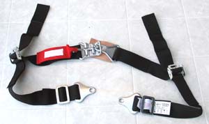
Here a 2" pull-up lap belt is ready for installation.
Note that the 3-bar slides will need to be adjusted so that they are as close as possible to the anchor plates and so that there is sufficient webbing length left to wrap-back through the slides.
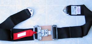
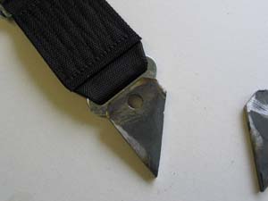
Here a 3" duck-bill lap belt is ready for installation.
Because the anchor plates are sewn into the belt their position is fixed and no adjustment is necessary - they simply need to be bolted to the mounting brackets.
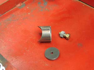
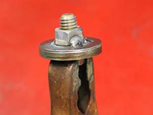
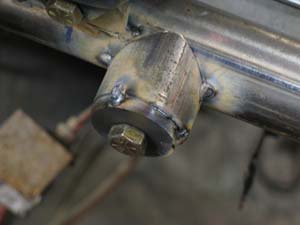
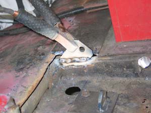
The slug is then welded to the tube with the nut inside.
Finally the mount is located in the proper position on the chassis and welded on.
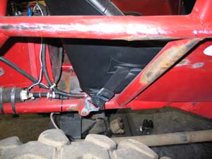
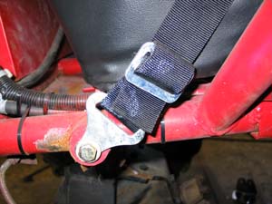
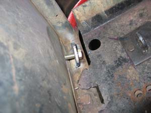
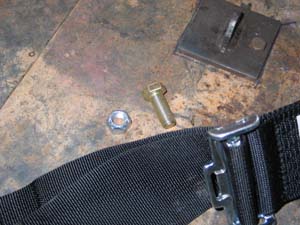
Either a locknut should be used inside the tube-mount, or the bolt should be installed with thread-locking compound.
Note the wrap-back of the belt through the 3-bar slide.
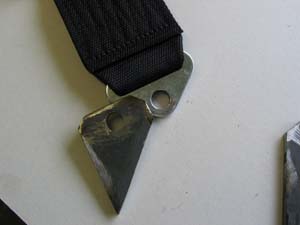
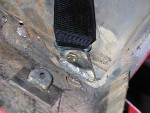
When tightening the fasteners on belt installation, be sure to hold the anchor plate steady at the correct angle.
Also double check for clearance between the bracket and the webbing to ensure the belt will not rub and abrade.
Here the anchor plate needs to be rotated counter-clockwise a couple of degrees.
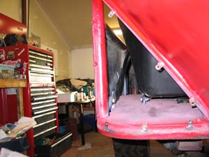
Outside lap belt anchor welded to chassis.
Width of anchor position is not perfect - it is slightly wider than the ideal location. Location of seat in chassis necessitates this slight compromise.
Belt length and angle are good.
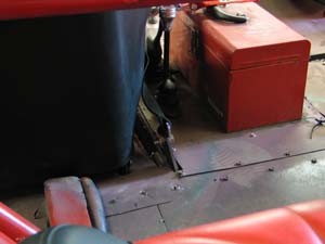
Inside lap belt anchor also provides good short belt length and proper belt angle, as well as being more optimally located at close to the same width as the seat.
Best practices would have the anchors mounted in double-shear brackets constructed from two tabs each.
This installer is apparently confident in the strength of single-shear cold-rolled 1/4" plate steel bracket combined with properly torqued 1/2" fine-thread Grade 8 fastener and locking nut.
In NO WAY are the pictures and examples shown here and throughout this article intended to illustrate optimal or perfect installations. They are provided merely as a way to illustrate the theory of best-practice installation rules. DO NOT blindly copy them.
Shoulder Belts
Shoulder belts are the parts of a restraint system that are most often improperly installed.
From the install diagram we can see that shoulder belts should be anchored behind the occupant's seat at a point located from zero to 10 degrees below a horizontal line extending rearwards from the top of the shoulder.
Occasionally manufacturers specify a maximum distance, in inches below the driver's shoulder, at which the shoulder belt anchor points can be mounted. To see why the location of the shoulder belt anchor points is such a big deal and to understand why it is a dubious practice to specify a height in inches as opposed to an arc in degrees, let's return to Larry and his seat:

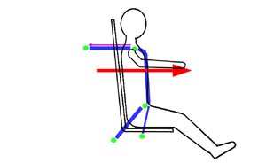
Properly restrained, with well-chosen anchor points at the level of his shoulders, good restraint geometry, and proper belt routing, the force of the crash imparted by the shoulder belts to Larry's clavicle's acts in a rearwards direction. This is indicated by the purple arrow.
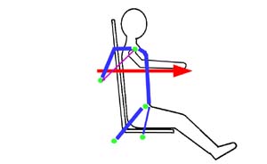
The force acts between the two hardpoints - one on Larry's body (his clavicle) and the other the shoulder belt anchor location.
Here we see Larry's shoulder belt mounting point is too far below his shoulders. The force still acts in a straight line between the clavicle and the mounting point.
The problem is, with the anchor point not directly inline with the shoulder, there is now a downwards component to the force.
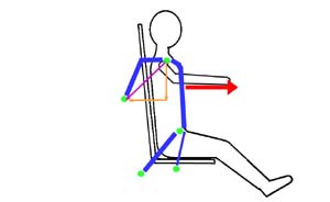
Physicists often study forces by breaking them into separate components called vectors. The magnitude (direction and size) of any force can be broken down into, and illustrated by, different vectors as long as the sum of the vectors is equal to the direction and size of the original force. Fancy way of saying we can break forces down into different components.
Here the original force of the belt on Larry's clavicle is represented by the purple arrow. The yellow arrows are the horizontal and vertical vectors or components that make up the original purple-arrow force.
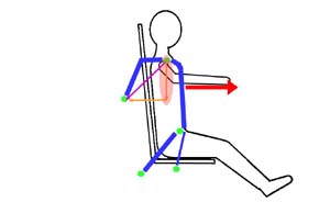
Now, the problem with the shoulder belt mount being too low is that, in a crash, the force on the clavicle (between the two green hardpoints & represented by the purple arrow) has a vertical component - illustrated here by the vertical yellow arrow (highlighted).
This vertical force component may act to compress Larry's spine in a crash, even when momentum just throws Larry forward.
In other words, mounting the shoulder belt anchor points too far below the shoulders places a risky and possibly unacceptable vertical force on the shoulders and may cause spinal compression - very bad!
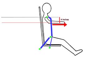
So now we come to the difference between specifying an acceptable shoulder belt anchor position in inches and doing so in degrees.
Those that specify a distance in inches often use the figure of 4". We'll use this in our example.
Note that none of these simple diagrams are drawn to scale - they are simply meant to illustrate a concept.
The problem with those that specify the mounting point in inches, is that they do not also specify how far back from the shoulders this 4" is to be measured.
To understand the problem with this, let's examine two different cases - one in which the shoulder belt is anchored 4" below and 3 feet behind the shoulders and then one in which the belts are mounted 4" below and directly behind the shoulders.
Here we draw a line 4" below Larry's shoulders, extending from directly behind the seat to the back of his chassis.
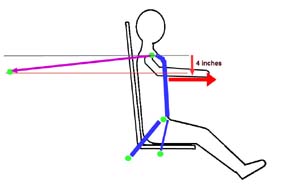
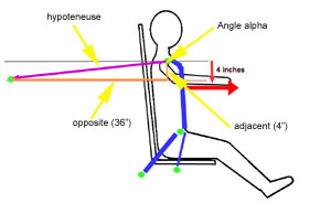
Now, you can see that the force (purple arrow) and its components (yellow arrows) form a right-angle triangle.
If we say the angle between the purple arrow and the vertical yellow arrow is alpha, we can label the triangle as shown:
purple arrow = hypotenuse
vertical yellow arrow = adjacent side
horizontal yellow arrow - opposite side.
Now, since we know the lengths of the adjacent and opposite sides, we can calculate the angle alpha using trigonometry.
tan (alpha) = opposite / adjacent = 36" / 4" = 9
therefore alpha = arctan (9) ~ 84°.
This means with the belt mounted 4" below the shoulder AND 36" behind it, it is mounted at an angle of (90°-84°) = 6° from horizontal (within the 10° rule).
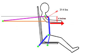
Now, using a little more Trigonometry, if we assume the purple force is 3000 lbs (purely for illustrative purposes, not intended to represent actual load), we can calculate the size of the vertical component, i.e. the load that will tend to compress the spine.
cos (alpha) = adjacent / hypotenuse
cos (84°) = adjacent / 3000
adjacent = 3000*cos (84°)
= 314 lbs.
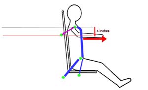
Now - let's see what happens when we mount the shoulder harness the same 4" below the shoulder, but this time only 6" behind it.
Here we see the load on the shoulder strap once again represented by the purple arrow. Notice the steeper angle.
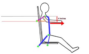
If we use the same labelling conventions as before, this time we calculate the angle alpha as:
tan (alpha) = opposite / adjacent = 6" / 4" = 1.5
therefore alpha = arctan (1.5) ~ 56 °.
This means that with the belt mounted 4" below the shoulder and only 6" behind it, it is mounted at an angle of (90°-56°) = 34 ° from horizontal (well outside the 10° rule, but within the 4" below rule if we were following that).
What does this mean?
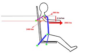
cos (alpha) = adjacent / hypotenuse
cos (56°) = adjacent / 3000
adjacent = 3000*cos (56°)
= 1678 lbs!!
That's 1300 more lbs of force, even though we followed the "rule" and mounted the shoulder harness anchor point only 4" below the shoulders!!!!
So it seems that specifying a maximum vertical distance below the shoulder at which it is acceptable to mount the shoulder harness anchor point is LUDICROUS without a corresponding minimum horizontal distance.
And since there are an infinite range of " x inches below and y inches behind" combinations that would result in an acceptable installation, it seems as though the only sensible specification is to specify a maximum number of degrees below horizontal at which the belt can be mounted - and according to the install diagram, the maximum acceptable angle is 10°.
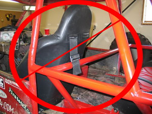
Because of the way many chassis are designed, there may be a temptation to anchor the shoulder belts too far below the shoulders.
In this rig, as in many others, there just happens to be a crossbar, about mid-seat height, right behind the seat!
Convenient though it may be, mounting the belts too low is wrong and probably dangerous.
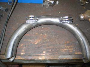
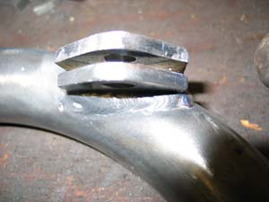
Remember that each anchor point must be able to withstand the load placed on it, so some reasonable care and attention is required in the fabrication of the mounts.
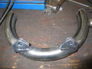
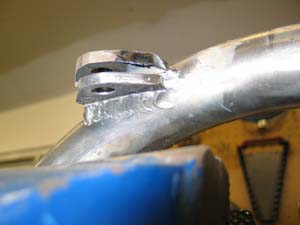
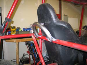
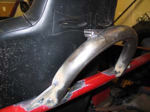
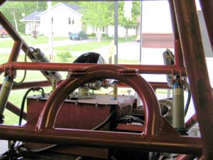
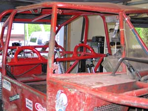

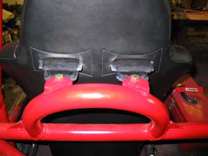
I can't be stress enough how important it is to take the time to mount the shoulder belts at the proper height.
You may not have to re-do the chassis to do it, but some fabrication will likely be required.
If you are not confident in your ability to design, fabricate, or locate proper driver restraint mounting points - seek qualified professional help! DO NOT blindly copy something you saw on the internet!
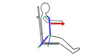
Having said all this about the importance of the height of shoulder belt anchor points, you may be wondering why, then, do you see some shoulder harnesses with such long belts, and why do you even see them labelled as "floor mount"?
Surely mounting the shoulder harness on or near the floor would violate all that we have discussed? Surely this would place way too much force on the spine in a crash?
Yes, this would probably be the case if the belt were mounted directly to the floor - BUT, there is a way around this problem if a "shoulder bar" is used.
Here we can see just such a bar mounted directly behind Larry's seat, at shoulder height.
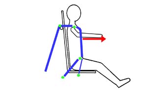
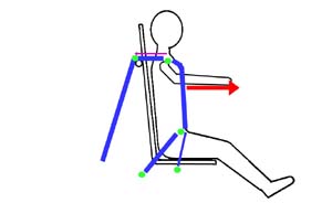
Since the shoulder bar becomes the effective hardpoint, as long as it is mounted within the 10° acceptable arc, the force on the shoulder straps in a crash will probably be in an acceptable direction, as indicated here by the purple arrow.
Having said this, many believe it is not best practice to mount the shoulder harness to the floor or any other sheet metal.
The minimum size for a shoulder bar is often considered to be 1.5” OD tube x .095” wall.
Be aware that rarely are the tubes of the internal seat frame sufficient to act as a shoulder bar for harness routing. Most seats are neither designed nor tested to carry shoulder belt crash loads.
Regardless of the height or angle at which the shoulder belts are anchored, in order to minimize belt stretch and the chance that the occupant may slip out from the harness in a crash, shoulder belts should be anchored as close to the shoulder as possible. For the best restraint of the occupant’s upper torso, shoulder belt anchor points should probably not be more than 8" behind the back of the seat.
In addition, with individual shoulder belts, as in an H-style restraint, the anchor points should probably be no more than 3-6” apart behind the driver's neck to prevent slippage off the shoulders. Where the seat has individual slots for the shoulder belts, the belts should probably be anchored so that they run straight back from the seat slots - with one exception:
If the shoulder belts are anchored more than 8” behind the back of the seat, the inside edges of the belts should probably converge at an angle of about 20-25° so that the anchor points are closer together than the belts are at the seat. This means that for belts mounted a long way from the back of the seat, the anchor points may need to be placed so that the belts touch or even cross over each other at the chassis anchor point. As a rule of thumb, shoulder belts should probably be crossed when the anchor points are more than 18 “ behind the seatback.
The shoulder belts of a driver restraint system will not properly restrain the driver if they are installed with an improper seat. They can not be used with a seat that either has no headrest or that has an integrated headrest but no slots for the belts. Proper quality seats are an integral part of the total restraint system and should be designed and manufactured to work with a driver restraint system. If your seat does not have the proper slots for the belts, or at least an adjustable headrest - it is likely unwise to use it; the shoulder belts can slip off the driver’s shoulders during a crash. The smart user will buy and use the proper seat! Never modify seats to create belt slots – not only is it likely to compromise the seats structure, but sharp edges created by cutting the seat can damage the belt’s webbing.
Finally, if the ends of the harness are too far above the shoulder then two problems can occur. First, tension in the shoulder harness may be increased and undue stress may be applied to the harness and its structural mounts. Second, excessive upwards angle of the shoulder belts may allow excessive occupant motion. If the harness belts are too far above the shoulder, they may provide little resistance to forward motion of the driver’s upper torso.
Wrap-around Style Installation.
Technically, one could attach any or all of the belts in the driver restraint system to the vehicle by wrap-around method. However, many sanctioning bodies forbid wrap-around mounting in anything but the shoulder harness mounts. Given that in an offroad rig the lower mounting points of the anti-sub and lap belts are in a pretty harsh environment (potential for webbing to abrade) and when one considers that it is unlikely that the rig will feature a bar in the optimum location and orientation around which to wrap the anti-sub or lap belt, it can be suggested that only bolt-in mounts should be used for anti-sub and lap belts; and that wrap-around mounting, if used, should be confined to the shoulder belts.
Wrap-around style mounting should include some method to prevent lateral or side-to-side movement of the belts. Several methods can be used, such as: roll bar padding secured with hose clamps, aluminum collars, or weld-on tabs.
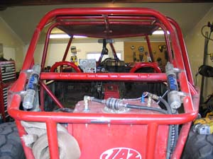
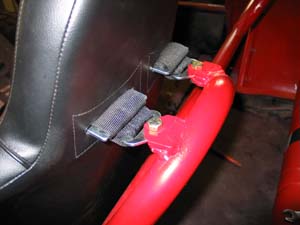
The shoulder belts for this rear bench seat use wrap-around style mounting.
To prevent unwanted lateral sliding of the belts small stops were welded on either side of each belt.
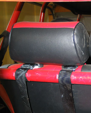
This wrap-around installation appears to illustrate that:
- The 3-bar slides are close to the bar.
- The belt is wrapped back through the 3-bar slide.
- There are stops to prevent lateral sliding of the belts on the bar.
Anti-submarine Belt
The anti-submarine belt should be anchored on or slightly behind the chest line, as indicated in the install diagram. Obviously it should be centred to the driver's body and the slot in the seat.
One caution is to account for the direction of pull on the anchor plate / mount. In a crash or impact situation, the anti-sub belt will likely pull forwards and slightly upwards on its mount. The installer will probably want to account for this in placing the mounting bracket. For example, one should probably avoid making the anti-sub belt bracket vertical, as this would likely put undue bending stress on it during a crash. One would probably want to avoid making it horizontal for the same reasons - the upwards pull may well place unnecessary bending stress on the bracket and anchor plate. The exact angle for the bracket will depend on seat height and the vertical distance between the bracket and the restraint system's main buckle when assembled and worn. Some believe that somewhere between 20-45° from horizontal may be about right.
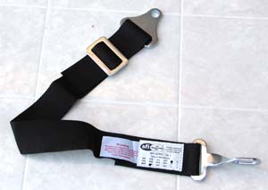
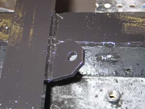
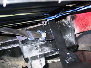
Test-fitting anti-sub belt installation under the seat.
The theory of the anti-sub belt installation may be relatively simple, but the execution takes some patience as you have to work under the seat - which usually means uninstalling and reinstalling the seat until anchor location, angle, and belt length are all correct.
Here once again the 3-bar slide needs to be snugged up to the anchor plate and once the installed length is adjusted, the belt will need to be wrapped back though the 3-bar slide.
Belt length should be such that the belt is snug when attached to the main restraint system buckle.
Common Installation Errors
For the safest possible installation, the chassis, seat, anchor points and driver restraint system should all be designed together and custom fit for the driver by competent, qualified professionals. If/when any design or installation compromise is necessary the individual installer or user will have to decide what is, and what is not, acceptable to them - hopefully with a full understanding of the consequences of any such compromise.
Some common installation errors are:
- Having the 3-bar slide too far from the anchor plate or wrap-around bar.
- Not properly wrapping-back the belt through a 3-bar slide.
- Mounting the shoulder belt anchor points too far below shoulder height.
- Not using a seat with the proper slots for the restraint system.
- Wrap-around installations with no provision to stop the belts from sliding sideways on the tube around which they wrap.
Wearing and Adjusting the Driver Restraint
Even a text-book perfect installation will not allow the driver restraint to properly restrain the occupant if the system is not adjusted and worn properly. Remember - the entire driver restraint system is only as strong as its weakest link!
To put on the restraint:
- Loosen the lap and shoulder belt tilt-lock adjusters.
- Place the left shoulder belt buckle on the link.
- Place the anti-sub strap buckle on the link.
- Place the right shoulder belt buckle on the link.
- Pull up on the hammer and insert the link into the latch until it is engaged by the hook on the end of the hammer.
- Press down firmly on the hammer until it clicks into place.
- If equipped, fasten the latch guard to the lap belt velcro.
- Centre the main buckle on the body, ensuring that the lap belt rides in the pelvic crest between the upper thighs and the pelvic bone.
- Make sure the anti-sub belt is snug with the main buckle in this position.
- Securely tighten the lap belts. Don't be shy - get 'em nice and tight.
- Tighten the shoulder belts with their tilt-lock adjusters.
- Check that tightening the shoulder belts has not pulled the lap belt out of position. If it has, the anti-sub strap and / or lap belts will have to be tightened more first. Loosen all tilt-locks and begin again at step 8.
- Check the position of the shoulder belt tilt-locks. They should be located approximately inline with the bottom of the sternum (breast bone). This should place them at least 10" below the clavicle (shoulder blade). If the shoulder belt tilt-lock is positioned too high on the body, it may ride up and cut into the driver's neck during a crash. A too-high shoulder belt tilt-lock also increases the chance of a clavicle (collar bone) fracture in an impact. If the shoulder belt tilt-locks are not properly positioned and the shoulder belts use a 3-bar slide at the anchor point, you can adjust the shoulder belt length as required to achieve proper tilt-lock positioning. If they do not have 3-bar slides (i.e. the anchor points are sewn in), you will have to re-do the shoulder belt anchor points on the chassis.
- With all belts securely tightened and properly positioned, fasten the sternum strap, if so equipped.
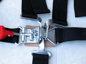
Once you have donned the restraint and tightened the belts, have an assistant:
- Check that all belt webbing passes through the seat slots straight and in-line with the main buckle, tilt-lock adjusters and the anchor points.
- Check that the belts are at an appropriate and acceptable angle as detailed in the installation instructions.
- Check that no belt bunches up or twists as it passes through the seat.
- Check that the lap belt tilt-lock adjusters are not positioned in, or too close to, the seat slots. Depending on the style of the lap belt, the adjusters should be at least 1.5" outside the slots (pull-up style lap belt), or at least 1.5" inside the seat slots (pull-down and duck-bill style lap belts). If the lap-belt tilt-lock adjusters are not properly positioned, and the lap belts use a 3-bar slide at the anchor point, you can adjust the lap belt length as required to achieve proper tilt-lock positioning. If they do not have 3-bar slides (i.e. the anchor points are sewn in), you will have to re-do the lap belt mounting points on the chassis.
More tips on wearing your driver restraint system:
- Never secure more than one person in place with each restraint (duh!)
- Never use the lap belt portion without the shoulder belts and the anti-sub strap.
- When donning the restraint, always ensure that the belts are not twisted.
- Always make sure the main buckle is centred on the body.
- Make sure the shoulder straps are evenly tightened on each side.
- Make sure the belts are not routed over any hard objects on the body such as jewellery, piercings, keys in pockets, etc.
- Make sure that heavy clothing doesn't impede your ability to properly tighten the belts.
- Never allow the belts to rub against any sharp objects.
- Never allow the belts to get caught in a door or any other part of the vehicle.
To exit a driver restraint:
- Undo the sternum strap, if so equipped.
- Loosen the shoulder belts with the tilt-lock adjusters (it may not be necessary to loosen the lap belt tilt-locks unless a driver or substantial clothing change is anticipated).
- Grasp and lift the latch guard, releasing the latch from the link.
- Thrust the lower torso slightly forward to cause the individual belt buckles to fall way from the link.
- Exit the seat.
Note: Steps 2 and 4 can be omitted in an emergency. Just undo the sternum strap, rip open the latch & link, and GTFO!
Consequences of Wearing the Restraint Too Loosely:
Any driver restraint should be worn properly tightened. Some of the possible consequences of wearing the restraint too loosely during an impact or crash may be:
Loose shoulder belts result in increased upper torso movement, increased head movement with resulting neck strain, and increased risk of contact with steering wheel or other objects in the cockpit. Contact inside the cockpit leads to injuries.
Loose lap belts lead to increased pelvic movement and resultant risk of submarining or ejection from the vehicle as well as placing extra load on the anti-sub strap; possibly exceeding its load capacity and causing it to break.
A loose anti-sub belt allows the lap belt to ride up, seriously increasing risk of abdominal injury, as well as increased risk of submarining and ejection.
Bottom line, when the belts are too loose the driver will not be properly restrained and in a crash or impact the result can be severe injury or death.
Inspection and Maintenance
Although they don't require extensive maintenance, driver restraints should nevertheless be periodically inspected and maintained:
- Keep the belts and latching mechanism clean and free of dirt, sand, mud, and debris.
- Avoid pressure washing the belts as this will drive dirt and sand into the webbing where it can abrade the fibres and weaken the belt.
- Do not use any harsh chemicals or solvents to clean the belts of a driver restraint system.
- Periodically inspect the restraint system for signs of wear, abrasion, or degradation.
- If the restraint is ever involved in an accident or fire it must be replaced, or at the very least returned to the manufacturer for inspection.
- Do not weld, grind, or cut on or near the harness or any of its hardware.
- Do not bend, straighten, or modify any of the hardware.
- Be aware that nylon webbing loses some of its strength when wet.
- Whether the restraint system is SFI certified or not, the life of the webbing in the belts is approximately two years under good conditions. The date of manufacture should be indicated on a tag installed by the manufacturer. On or before two years from this date, the webbing should be replaced. Some manufacturer's offer a service whereby the entire restraint system can be returned to them and they will replace the belt webbing and, if applicable, re-certify the restraint and return it. This can be done for significantly less cost than replacing the entire system.
Summary
Any driver restraint system will only function properly if:
- anchor points in the vehicle are correctly located.
- mounting brackets are correctly designed and fabricated.
- the correct hardware is used to connect the restraint to the vehicle anchor points.
- all hardware is properly tightened and maintained.
- the restraint is installed in such a manner that it can be positioned correctly on the driver's body.
- all belts are optimally routed from the body's hardpoints to the vehicle anchor points.
Below is a summary of some consider some important considerations when installing your driver restraint system. It is not an exhaustive list, nor does it replace the need for qualified, competent, professional advice, design, fabrication, installation, or use:
- Match your driver restraint to a properly constructed, fitted, and installed seat firmly mounted to the frame / chassis / roll-cage.
- Use a seat with the proper number of slots for the belts in the proper locations.
- Account for webbing and body stretch when locating restraint mounts.
- Keep all belts as short as possible to minimize the belt's stretch.
- Pad areas inside the cockpit that the occupant may contact.
- Ensure belt routing allows webbing to pull in a straight line against anchor point.
- Mounting brackets must be at an angle that is compatible with the direction of pull on the webbing.
- Preferred anchor mount is a double shear bracket.
- All mounting brackets should be attached directly to the frame / chassis / roll cage.
- Use appropriate hardware for the installation which might be 1/2" or 7/16" fine thread Grade 8 bolts and Grade 8 deformed thread locknuts.
- Fabricate mounts to be able to withstand the load that will be placed on them.
- Belts must not rub against any surface that will cause them to fray.
- 3-bar slides must be located as close as possible to the anchor plate or bar.
- The belt must be wrapped back a fourth time through the 3-bar slide.
- Install lap belt at an angle between 45° and 60° relative to the ground.
- Install lap belt anchor mounts seat- or pelvis-width apart.
- Anchor shoulder belts behind the occupant's seat at a point located from zero to 10 degrees below a horizontal line extending rearwards from the top of the shoulder.
- Anchor shoulder belts as close to the shoulder as possible. Ideally not more than 8" aft of the back of the seat.
- Anchor individual shoulder belts no more than about 3-6” apart laterally behind the driver's neck and so that they run straight back from the seat slots.
- If the shoulder belts are anchored more than 8” behind the back of the seat, the inside edges of the belts should probably converge at an angle of about 20-25°
- Shoulder belts should probably be crossed when the anchor points are more than 18" behind the seatback.
- Never modify seats to create belt slots.
- Wrap-around style mounting should be confined to shoulder belt installation and must include some method to prevent lateral movement of the belts.
- Anchor the anti-submarine belt on or slightly behind the chest line and centred to the driver's body / seat slot.
- Angle the anti-submarine belt mount to account for the direction of pull on the belt during a crash.
- Lap belt tilt-lock adjusters must not be positioned in, or too close to, the seat slots. Maintain a minimum of 1.5" clearance from the slot.
- Never secure more than one person in place with each restraint.
- Never use the lap belt portion without the shoulder belts and the anti-sub strap.
- When donning the restraint, always ensure that the belts are not twisted.
- Always wear the restraint with all belts properly tightened.
- Always make sure the shoulder belt adjusters are located at least 10" below the shoulder, inline with the lower sternum.
- Always make sure the main buckle is centred on the body.
- Make sure the shoulder straps are evenly tightened on each side.
- Make sure the belts are not routed over any hard objects on the body such as jewellery, piercings, keys in pockets, etc.
- Make sure that heavy clothing doesn't impede your ability to properly tighten the belts.
- Periodically inspect, clean, and replace the webbing in the driver restraint system.
Conclusion
No restraint system can keep you completely safe from harm. But you need to give yourself a fighting chance. To do so your restraint system must be:
- Installed properly
- Adjusted properly
- Worn properly
- Maintained properly
References:
|
