 |
Crane High Clearance Alloy Steering Knuckles By Bill "BillaVista" Ansell |
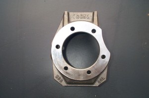 |
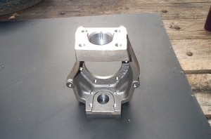
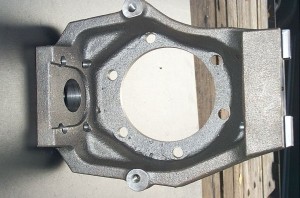
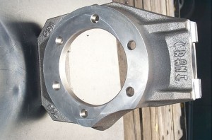
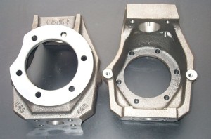
The HSC 60 Knuckles are absolute works of art. They are designed as replacement knuckles for Chevy/Dodge style Dana 60s. You can see from the pic the 6 bolt non-concentric GM spindle bolt pattern, and the semi-circular "indentation cutout" (arrow0 for the large single piston GM/Dodge style brakes. |
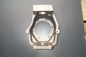 |
Massive chunks of cast Nickel-chromium-molybdenum alloy steel. DO NOT confuse the term "cast" here - it is not short for "cast iron" as it is so frequently used, it has nothing to do with the material - it is the process by which the material is made into the useful shape. This is very important, because WAY too many people misuse the term, and will be heard saying things like "I prefer steel to cast, because a cast part like that will just crack/shatter when it breaks, whereas the steel will bend" This is, of course, a gross misunderstanding of the facts, and is completely erroneous. |
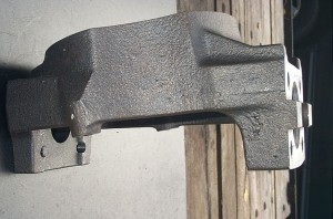 |
The knuckles will physically fit on Ford axle end forgings (inner knuckles or C's). But the user would have to swap to GM parts or go custom with:
Of course, this may be an ideal upgrade anyway, if you're swapping to 35 spline Cr-Mo axles at the same time, since you can just swap to Chevy stub shafts. |
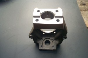 |
The material is ASTM A487. Nickel-chromium-molybdenum alloy steel. The equivalent SAE 4 digit code for this material that we are more familiar with would be 8630. That means it's like the chrom-moly alloy steel we are more familiar with - but with the addition of Nickel as a further alloying element. The exact specifications are as follows:
|
 |
Perhaps a quick review of alloying elements is required:
|
 |
Here are some yield strength numbers for comparison, taken from Taken from the 24th edition of the Machinery's handbook, table 9 - Typical Properties of Selected Carbon and Alloy Steels. 1030 being a typical plate steel. Recall that Yield Strength is the point at which a material exhibits a strain increase without increase in stress. This is the load at which a material has exceeded its elastic limit and becomes permanently deformed. 1030 normalized 50,000 psi, annealed 50,000 psi, quenched and tempered (1200°C) 64,000 psi |
 |
Comparing the numbers for normalized, we see 50kpsi vs 85kpsi - that's a 70% greater yield strength! It's clear then that this is a vastly superior material to the plate mild steel or nodular cast-iron that other alternatives are constructed from. |
 |
In addition to the superior material, the process of casting the steel eliminates the need to weld any parts of the knuckle together and therefore eliminates stress risers in high stress regions. Also, in a fabricated/welded part you have to be concerned with not only the selection of base steel and welding process but also what edge treatment is used to eliminate the slag, sharp edge, and maximize surface finish; what post weld heat treatment/stress relieve is used to minimize the residual stress from the welding process; and all of that has to be perfect - every weld, every time - and still you won;t match the strength and uniformity of a cast alloy steel part. |
 |
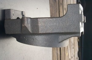
The casting also produces a product with an even, consistent surface finish that is extremely important in preventing stress raisers at the surface. Remember, stress raisers lead to the formation of tiny cracks that will eventually lead to fatigue and failure of the part. In addition, these knuckles can easily be welded, whether for customization or emergency trail repair (like you're ever going to need that!). |
 |
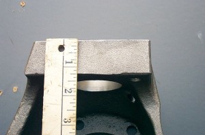
And finally, casting the part allows for optimum, consistent fillet radii in the transition zone between planes (translation - smooth curves allow stress to flow and not bunch up and break things) as shown by the blue arrow - without expensive and time consuming post-production machining. |
 |
So we have so far, a part that is superior to all other in material and manufacturing process, but what about design? Most notably, there is the huge increase in strength and fatigue life created by the increased web and flange thickness. A stock Chevy Dana 60 knuckle weighs approximately 16.5 pounds. The Crane knuckles weigh approximately 22 pounds. When material, process, size and shape are all taken into account it is extremely reasonable to estimate that these knuckles are at least twice as strong as stock knuckles. |
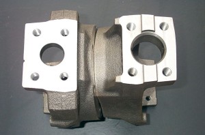 |
The post-casting machine work is also top notch. |
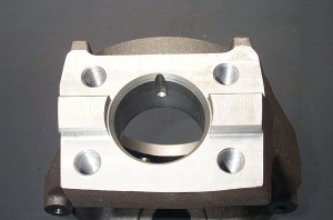 |
But by far the greatest innovation of the Crane knuckles is the integrated high-steer indexing system. There is a raised indexing tab cast into the top of the knuckle. This allows for use of a matching slot in the underside of the steering arm. If the parts are fit together closely enough, this ingenious system relieves the fasteners of the shear load caused by steering forces. |
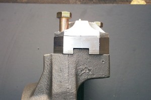 |
This indicates how the steering arm and knuckle are "indexed" together, creating the strongest possible joint at this critical place. |
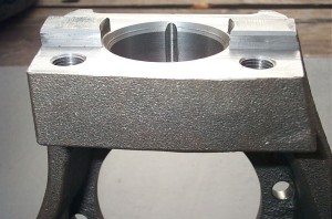 |
The idea is so simple yet brilliant, it leaves the rest of us smacking our heads and muttering "Why didn't I think of that?" More on the closeness of fit and steering arms later on. |
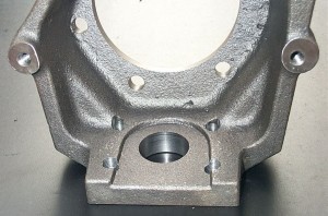 |
Continuing in the theme of excellent, innovative features that prove that Crane not only listen to customers needs, but as wheelers themselves understand what we want, the Crane knuckles have this excellent feature: Dual steering stops, as indicated by the arrows. This allows not only finer tuning of turning angles, which is critical with hydraulic steering and big axles/U-joints (like my Superiors and CTMs), but also a stronger steering stop system, as two sides will be working together to prevent further turning at full lock, in either direction. This is again critical with powerful hydraulic steering, and is key to preventing binding and possible destruction of axle yoke, U-joint, and knuckle itself as happens when the knuckles are over-steered. |
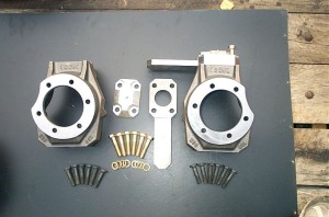 |
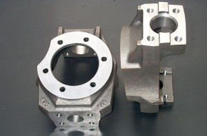
Here's a shot of the complete knuckle and steering arm package from crane. The knuckles and steering arms are shipped uncoated, and must be painted or otherwise coated prior to assembly and installation. |
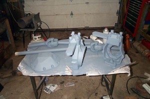 |
I used a 2 step process that has worked well for me before (and that is all rattle-can - no painting gear needed). Step one is to prime the raw steel parts with a high quality zinc rich self-etching primer. Not to be confused with cheap grey primer - this stuff is 2-3x more expensive but is the only stuff that will properly adhere to the raw steel. |
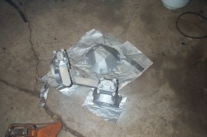 |
And for the top coat I chose a groovy silver to show off the parts. This is "Detroit Diesel Silver" industrial coating from Bowman. |
Compared to the stock knuckles |
|
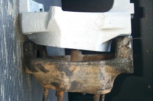 |
The extra beef is immediately apparent when the stock knuckles are compared side by side. A stock Chevy Dana 60 knuckle weighs approximately 16.5lbs. The Crane knuckles weigh approximately 22 lbs! |
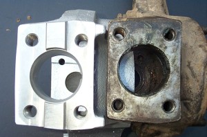 |
The Crane knuckles also use 9/16-18NF threaded holes for retention of steering arms / upper kingpin caps. Assuming a grade 8 fastener, this represents an increase in available clamping force of about 300 ft/lbs, an increase in maximum tightening torque capacity of 30 ft/lbs and an increase in shear strength from about 23,500 lbs to 29,800 lbs, or 21% per fastener. |
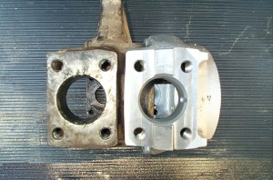 |
The lower bearing retainer threaded holes are the stock 1/2-20NF and stock spicer bearing caps are used, along with stock kingpin bearings and rebuild parts. |
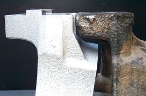 |
The area indicated by the arrow is the critically stressed area on a Dana 60 steering knuckle. This is where the stress concentrates as the steering forces act to try to twist the top of the knuckle off. |
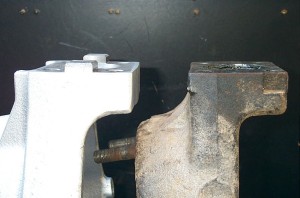 |
Notice not only the significant increase in material in the Crane knuckle, but also note the radius at the transition, chosen to minimize stress concentrations in the part. |
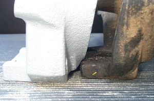 |
Every area possible is beefed up compared to the stock parts. |
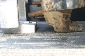 |
Thicker everywhere. |
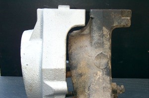 |
Note the extra wide vertical "rib" , and the beefy steering stop in the Crane knuckle. |
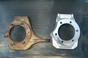 |
For those using high-steer , the elimination of the useless stock "steering arm" gives a nice clean appearance to the knuckle. |
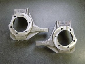 |
However, the Crane knuckles are available in "classic" form, with stock Chevy location steering arms and stock 1/2-NF threaded holes for the kingpin cap bolts/studs. These "classic" 60 knuckles from crane also do not feature the high-steer indexing system, and can easily be used with any existing dana 60 High Steer Arm. |
The Steering ArmsNow we come to the Crane Indexed Steering Arms. These are a brilliant idea, the execution of which is in need of some improvement. |
|
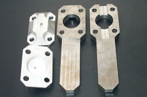 |
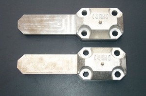
Here we see the basic design of the arm. The arms are machined from a single piece of mild steel that is initially 1 inch thick. They fit over the kingpin bushing and spring, and have a separate cast aluminium cap. The attachment holes are straight-cut holes for 9/16" bolts. |
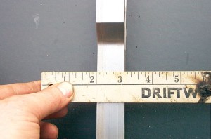 |
Thickest side of arm is 1 inch thick. |
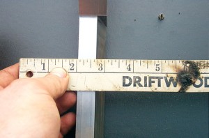 |
Thinnest side of arm is 5/8" thick. |
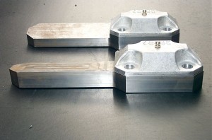 |
They have an angle machined into the steering arm, that is intended to allow the "cancellation" of the stock kingpin inclination angle, resulting in a horizontal surface for the steering linkages rod end attachments. The theory is, that by doing so, regardless of whether the steering linkage uses Heim joints or standard automotive tie rod ends - by having the steering arm horizontal at rest, the least amount of valuable misalignment angle available in the joint is consumed in it's static mounting position. This in turn would leave the greatest amount of misalignment angle available for accommodating suspension travel without binding the steering linkage. |
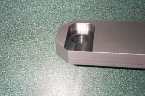 |
The theory is sound, and a good idea, but the problem is, if you do this, BOTH sides of the steering arm must remain parallel to one another - which they do not in the Crane arms. This is because the head of the bolt and the nut must be parallel to one another, you can't have either trying to seat against an angled surface (in the case of a TRE, the tapered stud and nut must be perpendicular to one another - the result is the same) and therefore - the 2 sides of the arm must be parallel. If you machine an angle into one side of the arm, as in the Crane arms, you have to cut a slot for either the nut or the head of the bolt. |
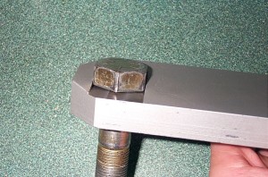 |
This is what I had to do mount the arms, but is not a particularly good solution for 2 reasons:
|
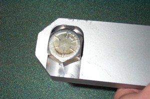 |
The much better way to eliminate the stock kingpin inclination would be to start with a much thicker piece of steel and mill both sides the same angle, eliminating the angle, but leaving full thickness (an inch or so) and both sides of the arm parallel to one another. If it were determined that this approach would involve too great an expense in material and time, personally I would much prefer to simply have flat 1" thick arms, rather than having them 5/8" thick around the hole and having to mill a slot. There is one neat benefit to the "machine slot" approach though - you can machine the slot just big enough for the bolt head and then not require a tool on the head of the bolt during assembly or disassembly. |
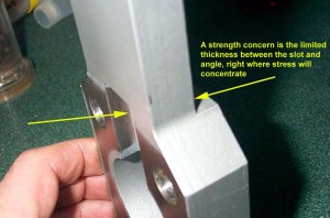 |
Finally, the machined angle presents one last potential problem area. And that is the very limited thickness left in the arm, right were the indexing slot overlaps the arm where it is angled (yellow arrows). Unfortunately, this happens right where there is a major section change from the "body" of the arm to the arm itself. As it is, this will be a highly stressed area as the steering forces attempt to try and twist the arm off here. The result is, the machined angle leaves one side of the arm just 5/8" thick, and then on top of that, the indexing slot in the arm removes even more material (I forgot to get an exact measurement, but it's probably about 1/4" deep) leaving the arm only about 1/2" thick at the thinnest part. We shall see how they hold up, but this doesn't seem enough for my tastes, and the prospect of a steering arm failure on the trail is not a thrilling one. |
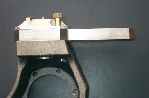 |
Installed on the knuckle the arms look like this. This side looks just the job... |
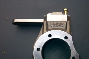 |
...but the "thin" side looks, well, not as beefy as it could, and probably should, be. |
 |
As for retention, the arms themselves are retained with four 9/16-18NF fine thread SAE grade 8 bolts and lock washers. The 9/16" bolts are an upgrade in size from the stock 1/2" fine thread, but the straight holes in the arm and separate cap result in a lack of a true zero-clearance fit for the fasteners. Without either tapered nuts (as in stock D60 hardware) or tapered, split cone washers (as in D44 style hardware) there is a possibility of loose fit around the fasteners, leading to relative motion between arm and knuckle, fatigue, and possible bolt failure. |
 |
Of course - in this regard, the Crane arm and knuckle combo is unique, and so the normal rules and concerns don't apply exactly as they do to other arm and knuckle joints. The ingenious indexing system, consisting of the cast chrom-moly key on the knuckle and the matching slot in the steering arm combine to ensure the strongest, slop-free union possible in a joint of this kind. The official tolerance on the difference between the key and slot is plus or minus 0.001", with the slot being just very slightly larger than the key. Technically this is known as a transitional class fit. |
In practice, the mating between arm and knuckle key is close, but not what I would describe as "tight". The arm drops over the key with no persuasion required for assembly. Once on the knuckle, with key indexed in slot, but no bolts installed, there is just the teeny-tiniest perceptible wiggle. Install the bolts, without even tightening them ,and the whole joint is tight and wiggle free. I have no practical concerns that there will be relative motion between the arm and knuckle once installed and torqued to spec - but, theory says it is possible, particularly if the bolts loosen somehow. And we are talking about a desire for the "best" - the ultimate. With that in mind, I would personally prefer to see the key/slot fit be a true interference fit (with the slot being 1-3 thou smaller than the key) and the joint require slight force or heating for assembly. |
|
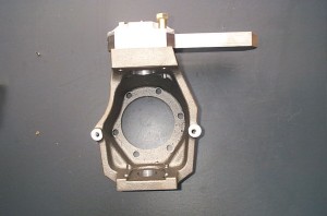 |
So in summary, we have: Advantages:
Areas for improvement:
Overall a good first design from Crane, with an innovative and extremely useful indexing system, that could use some refinements. |
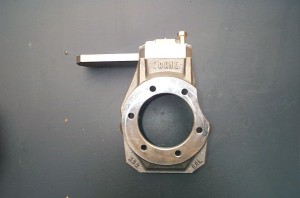 |
*** BREAKING NEWS *** Here's the really cool thing - I shared all of these initial opinions of mine with Tim Plamondon, one of the key players at Crane High Clearance (who is, incidentally, a fourth or fifth generation pattern maker [that's a dude who makes things from molten steel!], a heck if a nice guy to talk to, with a keen interest, super technical ability, and great customer service) I also shared with him a few other observations and design ideas I haven;t yet published here, as he has agreed to work with me in designing and developing the ULTIMATE D60 high steering arm, one that can truly take it's place beside their great knuckles. Stay tuned - I will post results, impressions, and more testing here as the project progresses. |
InstallationAs I mentioned in part 2 of the BV-60 article, my intent was never to make this article a detailed installation article - I'm assuming that we're pretty comfortable with axle R&R at this stage. However, should you wish to review or study detailed information regarding the building of a D60 front axle particularly swapping knuckles on a Dana 60 front axle, that information is readily available in several other articles I have writen. You can check out: My detailed article that covers the whole process at: Dana 60 front axle kingpin rebuild Or, for more general dana 60 information: The original Spicer D60 front axle maintenance manual The one ton axle tech manual compiled from US military manuals The Dana light axle service manual (torque and setup specs) With that - here are some pics and notes from the installation of the Crane knuckles on the BillaVista-60 |
|
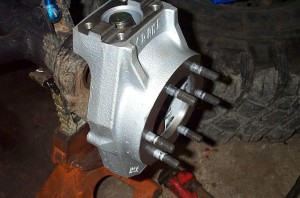 |
The 6 new spindle studs are installed in the knuckle, and the knuckle installed on the axles end forging. |
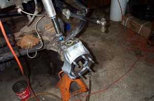 |
Kingpin nylon bushing installed in top of knuckle. |
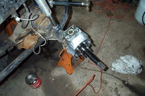 |
Superior cr-mo axle installed. |
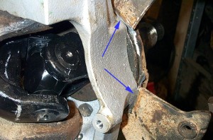 |
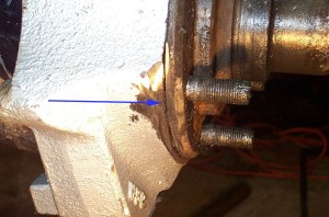
Here's a little something I, as usual, didn't anticipate. I have a "custom" front brake setup on my front Dana 60. Instead of the stock brakes, I use a 3/4 ton calliper and rotor, that requires a custom calliper bracket. This custom bracket is really nothing more than the grafting together of 1 ton and 3/4 ton brackets. However, because if the extra beef of the Crane knuckles, at assembly time, I found my custom bracket would no longer fit flush against the spindle, due to slight interference as indicated by the arrows in the pic at left. |
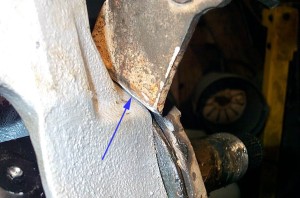 |
Slightly closer view of the area in question. As you can see in the pic, I ground down the calliper bracket as much as possible, but in the end... |
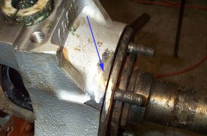 |
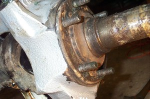
I just had to take my 4.5" mini grinder and "tidy up" the knuckle just a tad. You know, I discovered you really don't know what kind of (wo)man you are until you have to take a grinder to almost $1k worth of brand spanking new chrom-moly knuckles!! |
 |
But it was really just a very light smoothing, and I should emphasize, certainly no fault of the Crane knuckles. If you have stock 1 ton brakes, everything will fit like a glove, no grinder required! |
 |
But if you do have some sort of custom brake setup - you should be aware of the possibility....and prepare yourself psychologically :-) Here we can see everything is tidied up nicely and I'm back in business. |
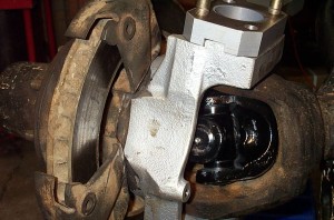 |
Custom brakes fitted up, big fat Cr-mo knuckles, axle shafts, and U-joints Ohhhh yeaaaa baby! |
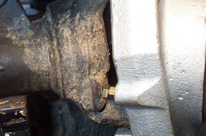 |
Steering stop being adjusted and tested. I used a grade 8 bolt with an extra nut for locking. |
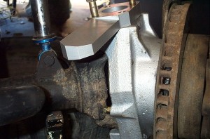 |
Un-machined steering arms being test-fit. You can clearly see the angle in the arm cancelling the kingpin axis inclination. |
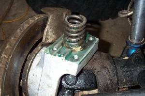 |
Kingpin spring and spring retainer installed. |
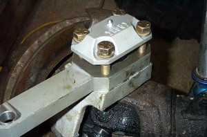 |
Kingpin cap being installed. |
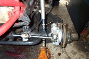 |
The finished package, ready to rock. |
 |
Sources: Crane Hi Clearance 5751 Fairfax St Commerce City Joshua Lowenstein |
|

