 |
Flashing LED Brake Lights By Bill "BillaVista" Ansell |
IntroductionAll models of the 124 Spider have the same three red LED brake lights (or stop lights) - Left and Right conventionally located brake lights and a single Center High Mount Stop Lamp (CHMSL) mounted on the top edge of the trunk. However, due to the very low profile of the car, it has been reported that Spider pilots can be at risk of a rear-end collision when slowing or stopping (especially during sudden hard braking) as the hordes of minivan/truck/SUV/Crossover drivers are either somehow unable to see the car from their lofty perches or, if they do see it, so awestruck with its beauty and uniqueness they loose what little situational awareness they had. |
 |
Thus, it stands to reason that any attempt to increase the car's visibility during braking could offer an increase in safety...as has been the case forever for motorcycle riders. In this project I do two things to augment the Spider's attention-getting power while braking...first I add two additional red LED brake bulbs to the rear fog lamp / reverse light housing (in the NA market, we do not get the rear fog lights that our overseas cousins do so the red lenses in the housing are unused); then I wire in a flasher unit so that the CHMSL and new auxiliary lower brake lights all initially flash in unison when the brake pedal is applied. The unit I used has a flash pattern of 4 very rapid flashes, followed by 4 slower flashes followed by steady on. Here's the step-by-step of how I did it: |
||
 |
First, you will need two "T10" bulb sockets. I used a simple rubber push-in type that require only a round 9/16" hole for installation. I found a set of 10 on AliExpress for $2.99 US. You can see the ones I purchased at THIS LINK. Product Name: T10 Light Socket |
|
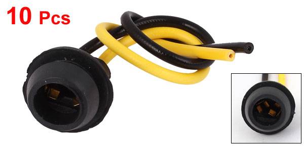 |
Close-up of an individual socket, showing the lips that secure/seal it in place. | |
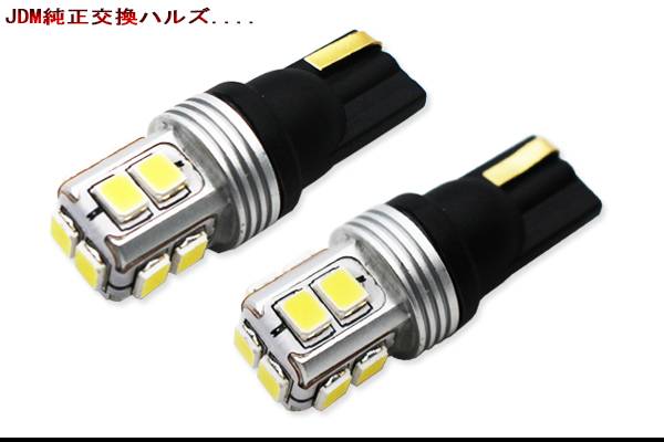 |
You will also need a pair of red LED bulbs. They must be LED, you cannot mix the stock LED CHMSL and incandescent bulbs in the same circuit. I bought a pair from AliExpress for $6.74 US from THIS LINK. They are sold in different colours, so make sure to pick red (picture at left and the next two pictures are of the white light variety). |
|
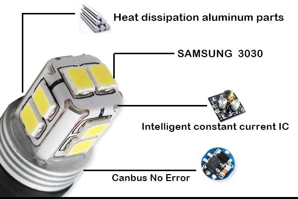 |
The specs are as follows:
|
|
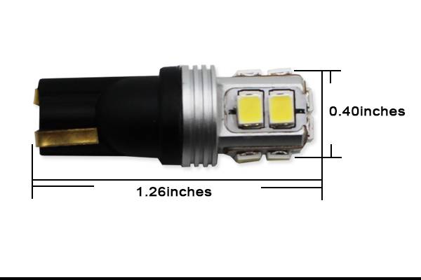 |
Dimensions. | |
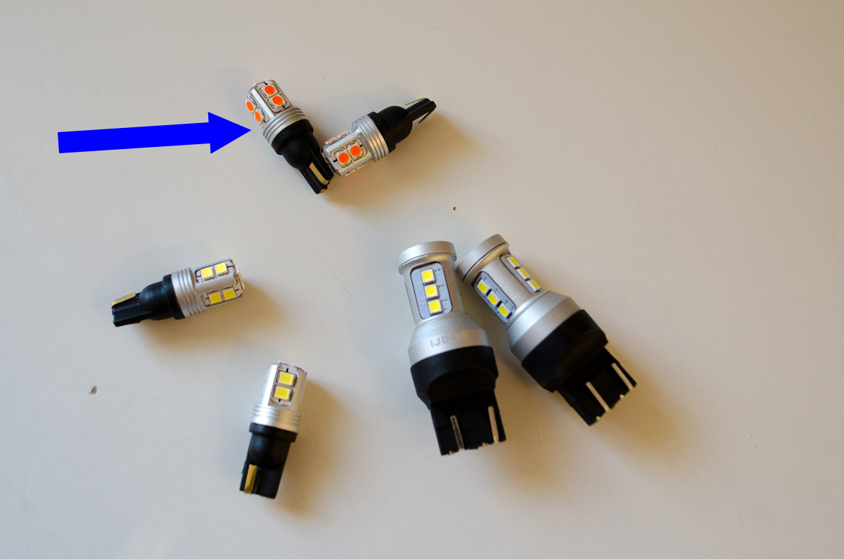 |
Here's the red version (blue arrow) next to some other bulbs for different projects. | |
.jpg) |
For scale | |
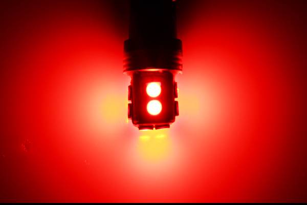 |
Red LED lit up. | |
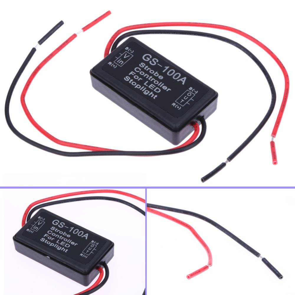 |
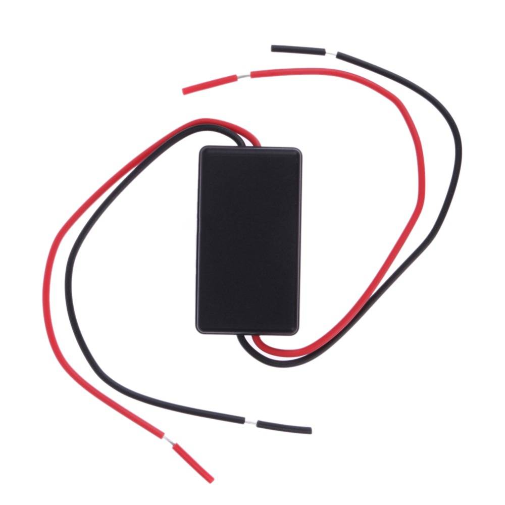
Finally you will need an LED flashing module. I bought this one from AliExpress for $2.56 US from THIS LINK. Specs are:
|
|
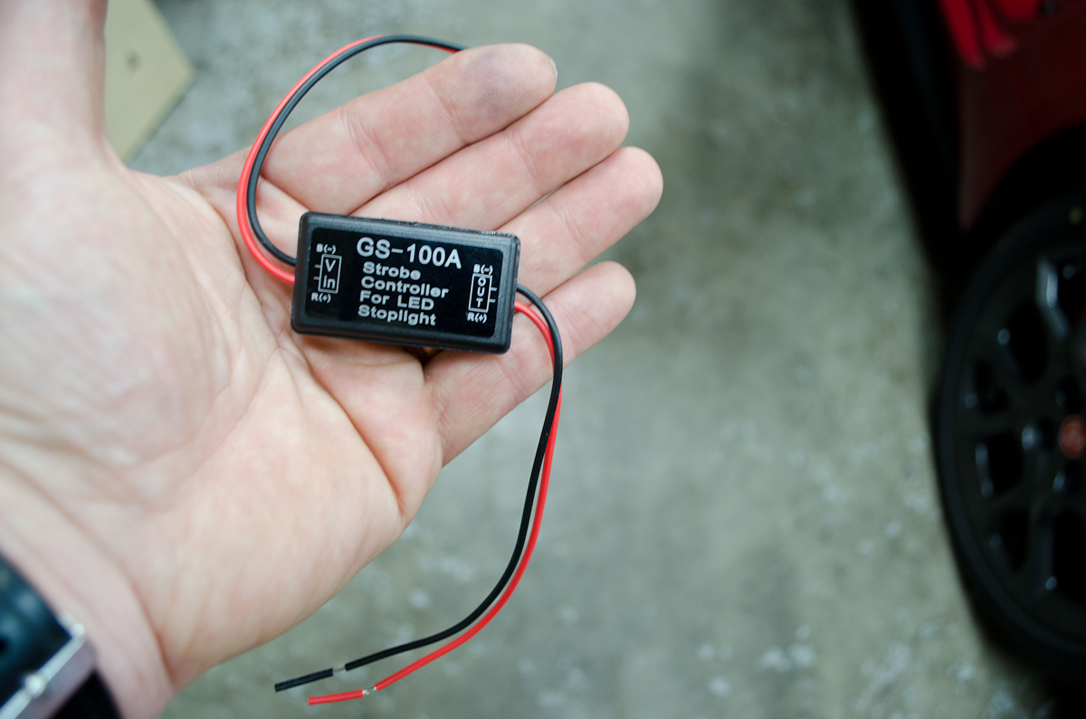 |
For scale. It's actually quite small, and it comes with a little piece of double-sided adhesive tape to secure it in place in your chosen location. Wiring is very simple, you simply connect the IN and OUT positive and negative wires in0line with whatever LEDs you want to flash. |
|
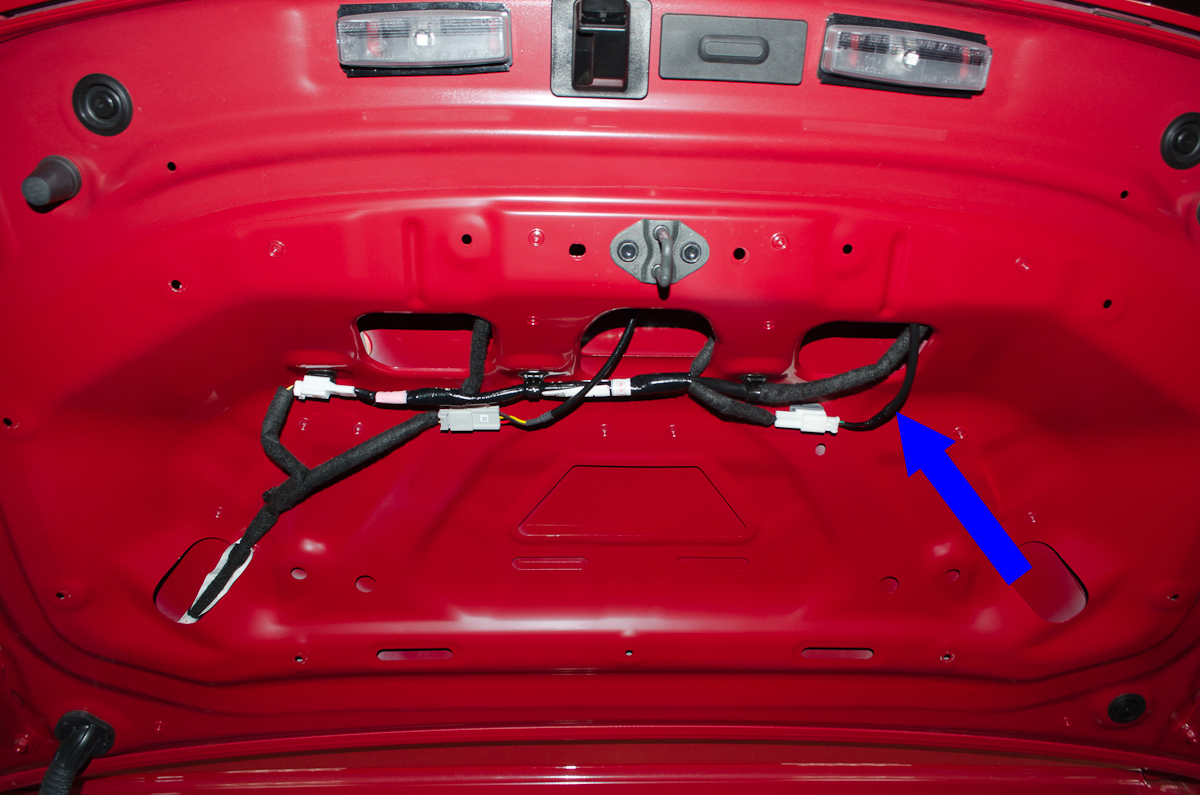 |
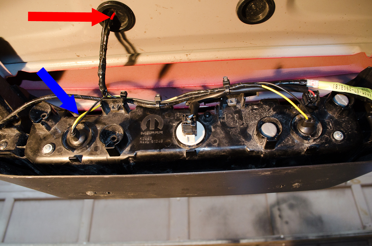
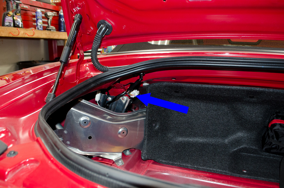
For example, if you didn't want to add the two auxiliary LED bulbs that I did (or if you have rear fog lights) you could still use the flasher unit to flash the LED CHMSL. To do so, remove the plastic pins securing the cover on the underside of the trunk lid to expose the wiring. The wires for the CHMSL are indicated here by the blue arrow. |
|
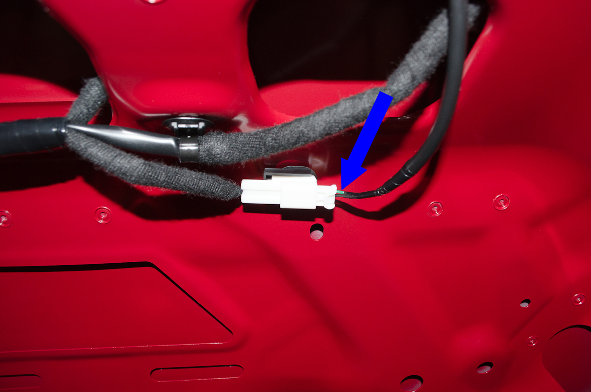 |
The green wire is the (+) and the black is the (-). To wire in the flasher you cut both wires, then:
|
|
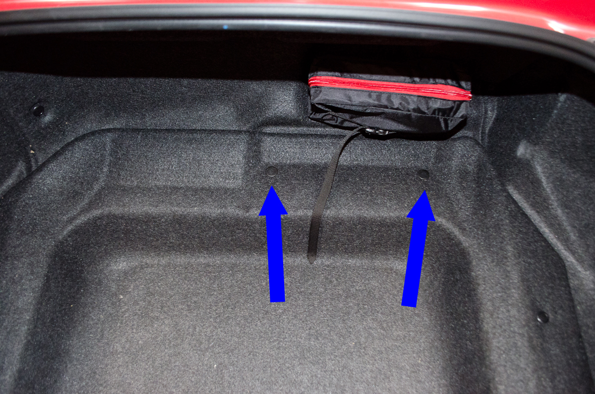 |
However, if you're adding the extra brake light LED bulbs, the next step is to remove the bottom and left side trunk liners. Remove the two push-pins at the forward edge of the trunk by prying them up with a small pick or screwdriver. These two are different from all the rest (having no centre locking pin), so remember where they go. |
|
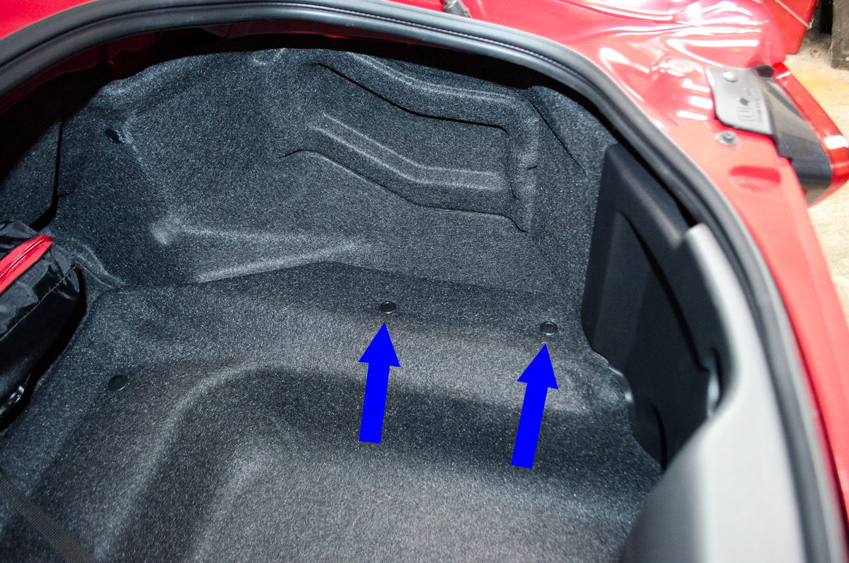 |
Move on to the two on the right side. These and all the remaining pins are the same style. To remove them you pry up the centre pin, unlocking the fastener, and then pull out the whole pin. | |
 |
Next, remove the remaining 6 pins from the left side. There is one behind the rear plastic panel (location indicated by the red arrow) which you have to pry the plastic panel forward to access. With all the pins removed, remove the bottom liner and then the left side one. The left one takes a bit of wiggling to get out (and back in). |
|
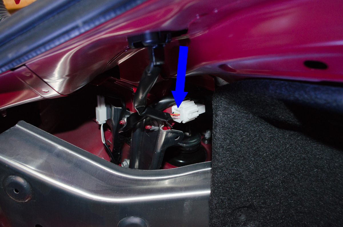 |
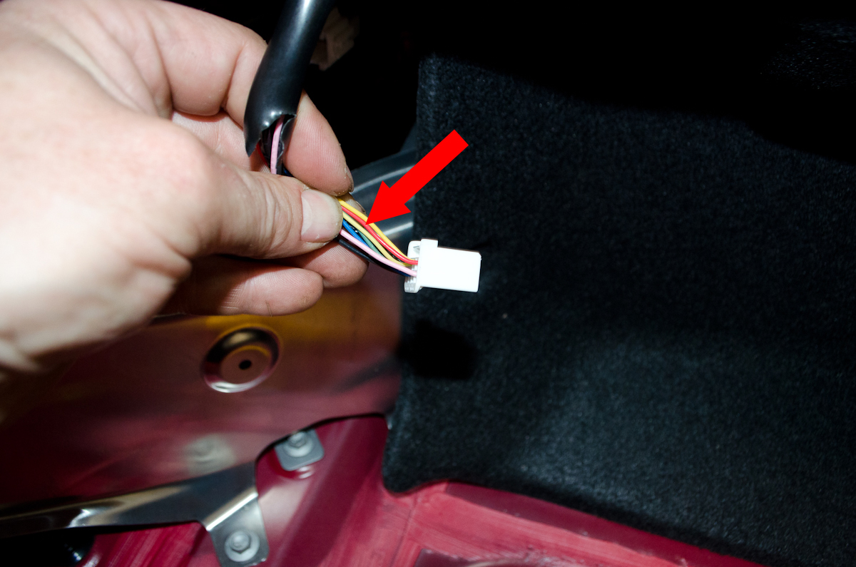
Before going any further, disconnect the negative wire from the battery, and press the brake pedal once to ensure no current in any of the car's circuits. With the left side liner removed, we can see the connector that has the wire that powers the CHMSL. |
|
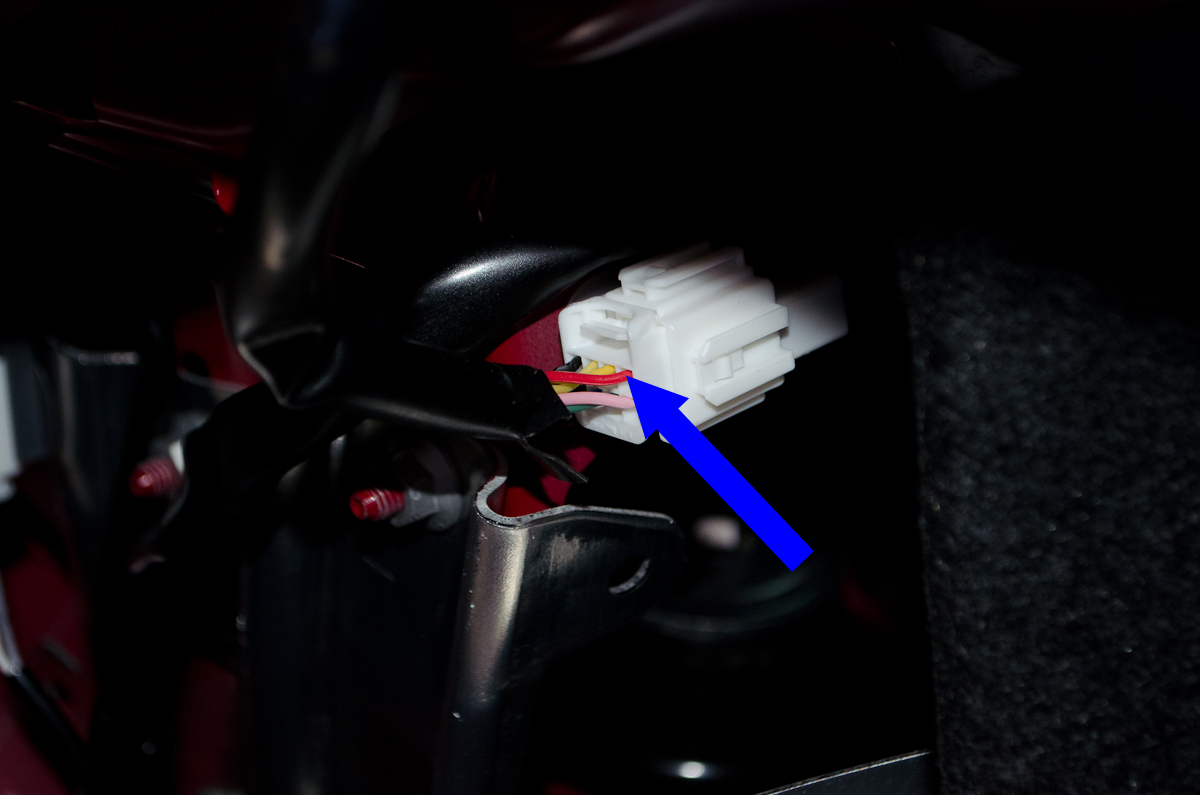 |
It's the red wire. This is the one we will tap into to power the flasher module. But before we get to the wiring, we need to install the two new bulb sockets in the lower light housing. |
|
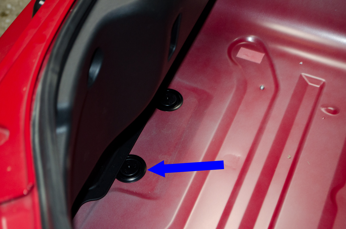 |
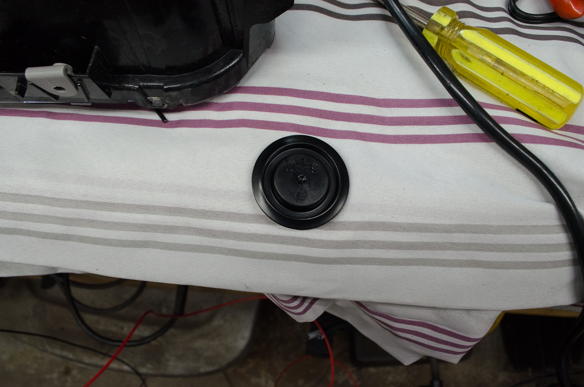
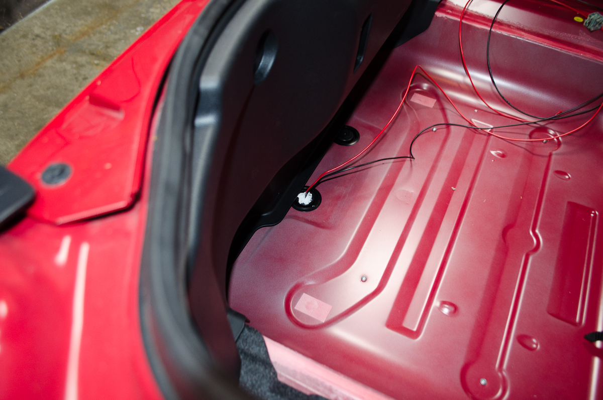
To run the wires to the new lights, we're going to remove this grommet and cut a little slit in it, then run the wires through it. | |
 |
Grommet removed. | |
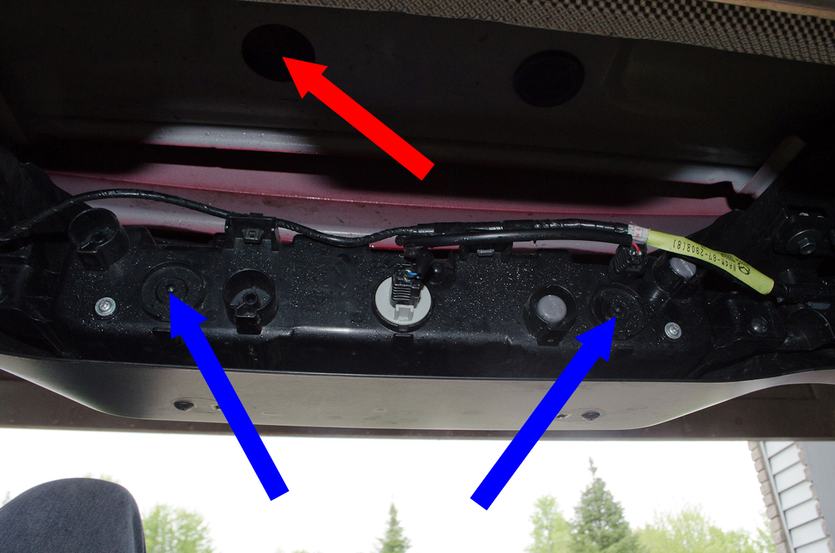 |
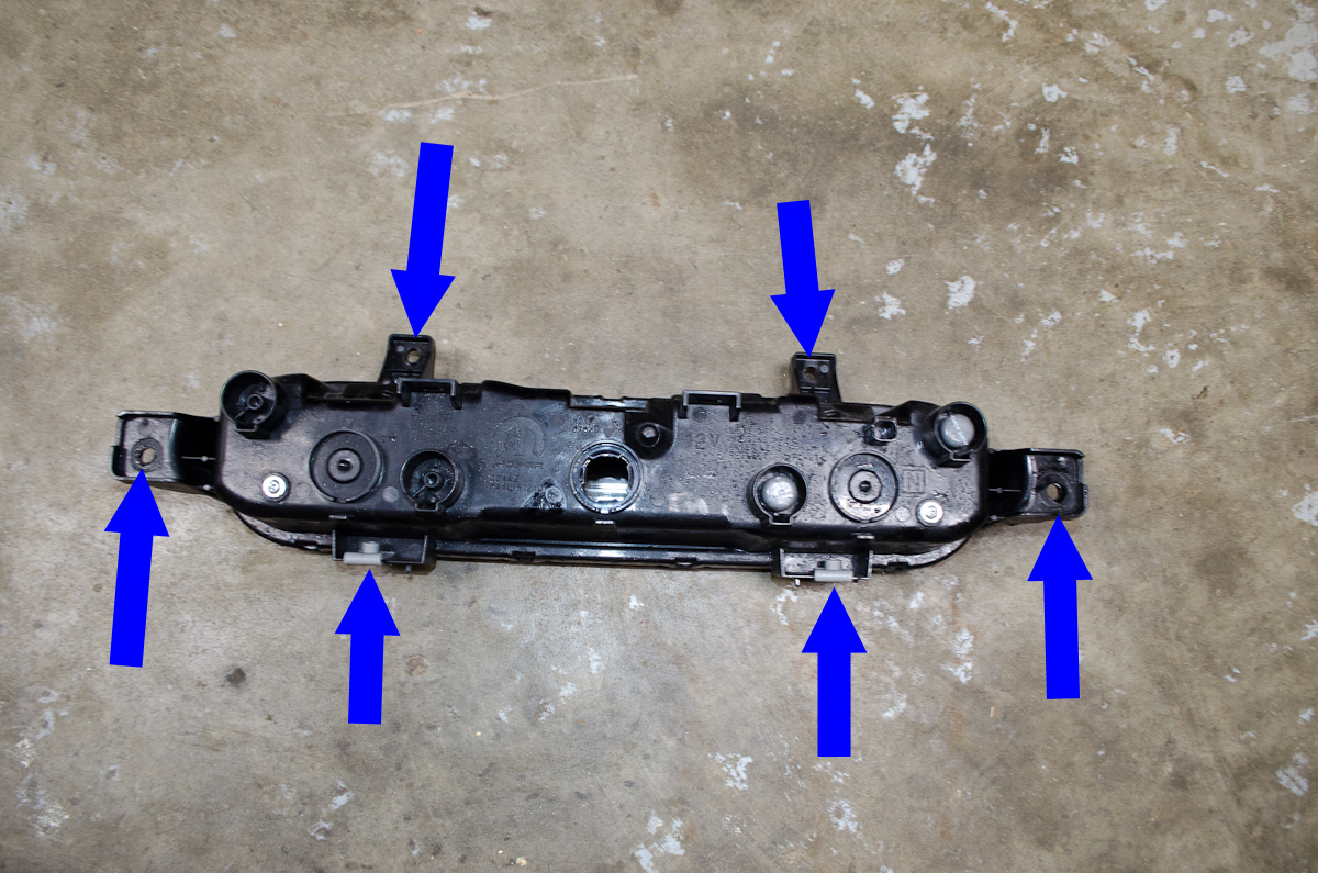
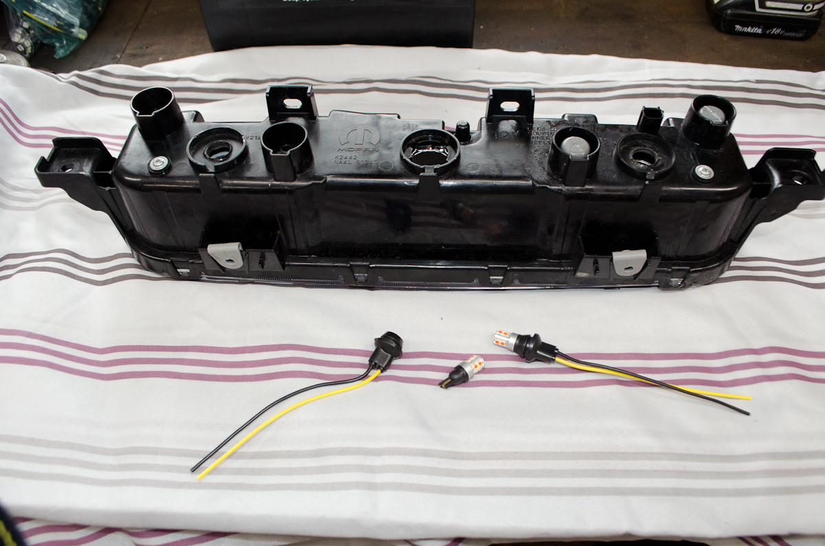
Time to crawl under the car from the rear. You can do this without jacking the car up, but you'll have more room and be more comfortable if you do raise the rear end a bit. It's advisable to remove the light housing from the vehicle for the modification as it's really cramped under there. The blue arrows show the locations where we're going to be installing the new LED bulbs, and the red arrow shows the underside of the grommet through which we're going to run the new wires. |
|
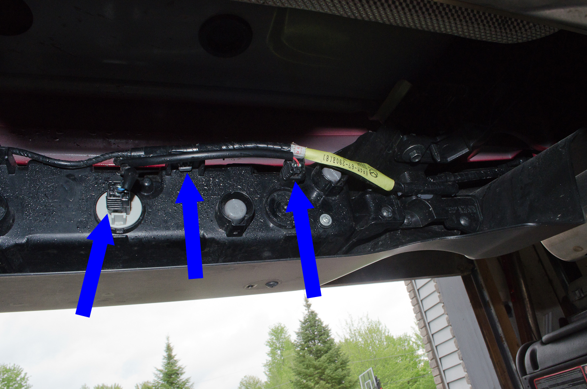 |
Before we remove the screws and take out the assembly, there are a few things we must disconnect. From left to right in this pic, remove:
|
|
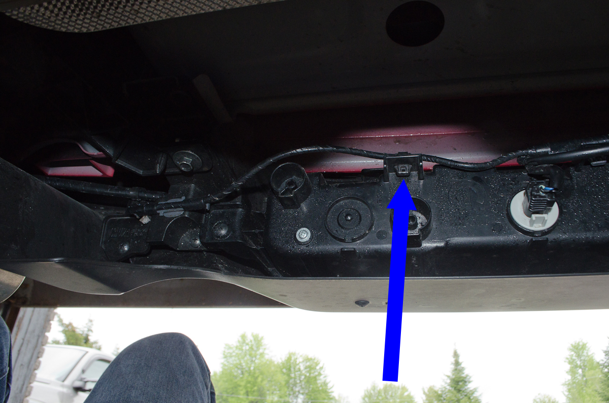 |
And finally, one more wiring harness clip, by squeezing the little tabs and pushing it up through the slot. | |
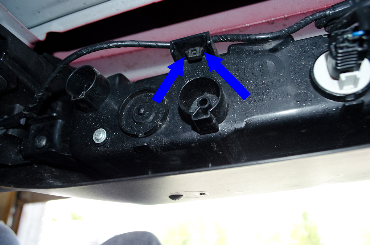 |
This close-up shot shows the little tabs or legs that you need to squeeze or press in to remove the wiring harness clips. | |
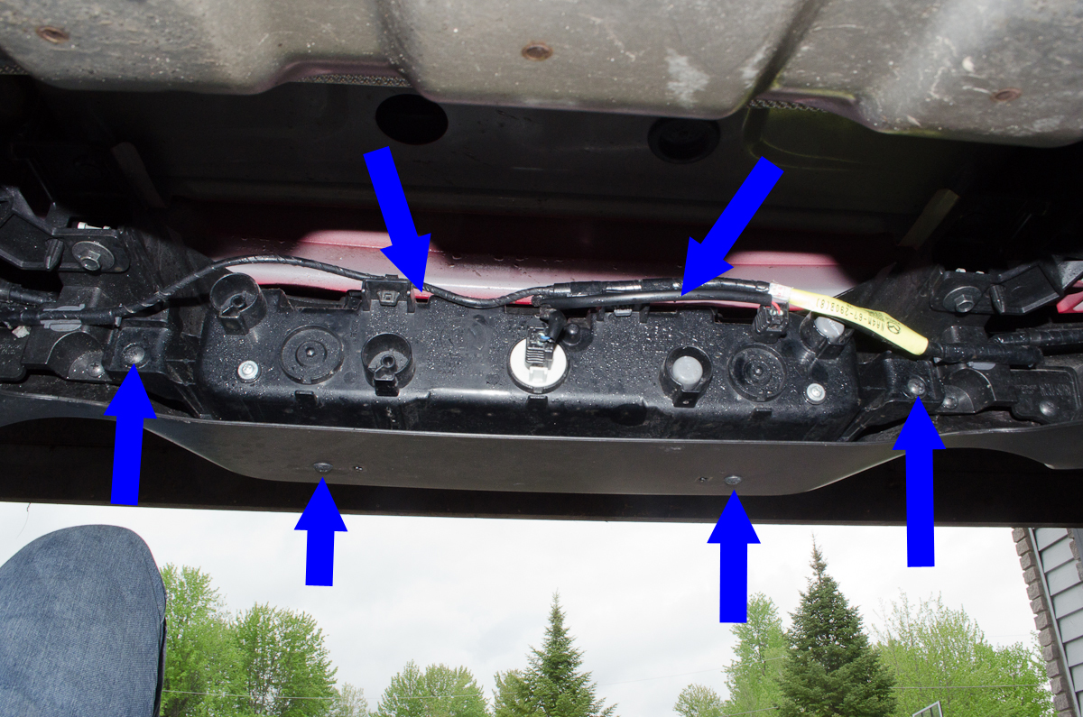 |
With all the disconnections made, remove the 6 phillips-head mounting screws. The two at the top are not shown in this pic, but their approximate locations are shown by the top two blue arrows. They're not too hard to reach, but my camera would not fit up there to get a good shot of them. With the 6 screws removed, carefully wiggle the housing out of the car. |
|
 |
This shot of the rear of the housing removed from the car shows the location of the six mounting tabs where the screws go. | |
 |
Bottom side of the housing. | |
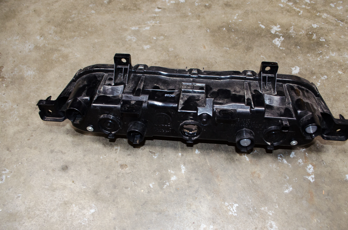 |
Top and rear of the housing. | |
|
Front of the housing. | |
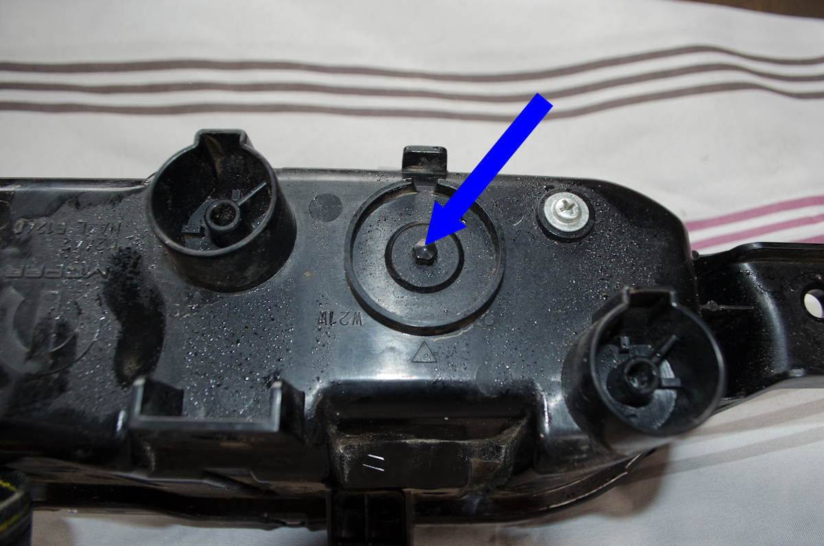 |
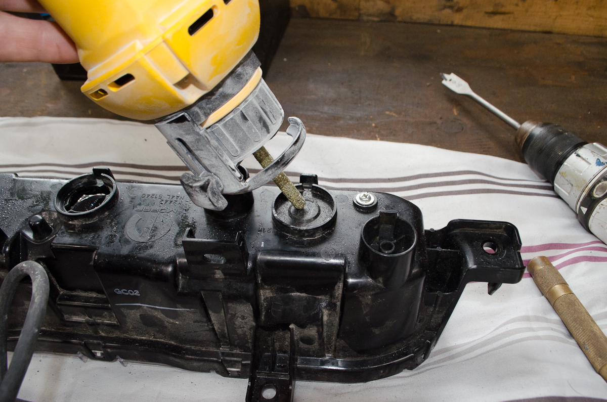
The two spots where we need to drill 9/16" round holes to install the bulb sockets have a small nipple molded into them which will make drilling difficult so they must be removed. | |
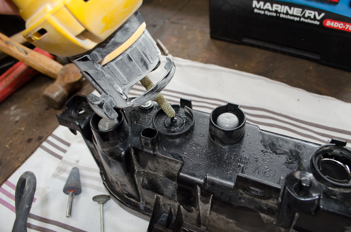 |
I used a rotary tool with an abrasive bit to grind them away. With patience and care you could use a sharp utility knife or a small hacksaw blade or even a small file. |
|
 |
Removed. | |
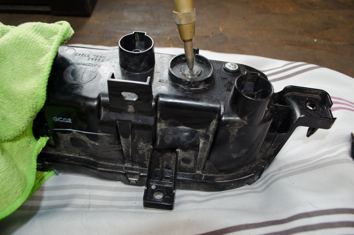 |
With the nipple removed, centre-punch the location so you can drill a perfectly positioned hole. | |
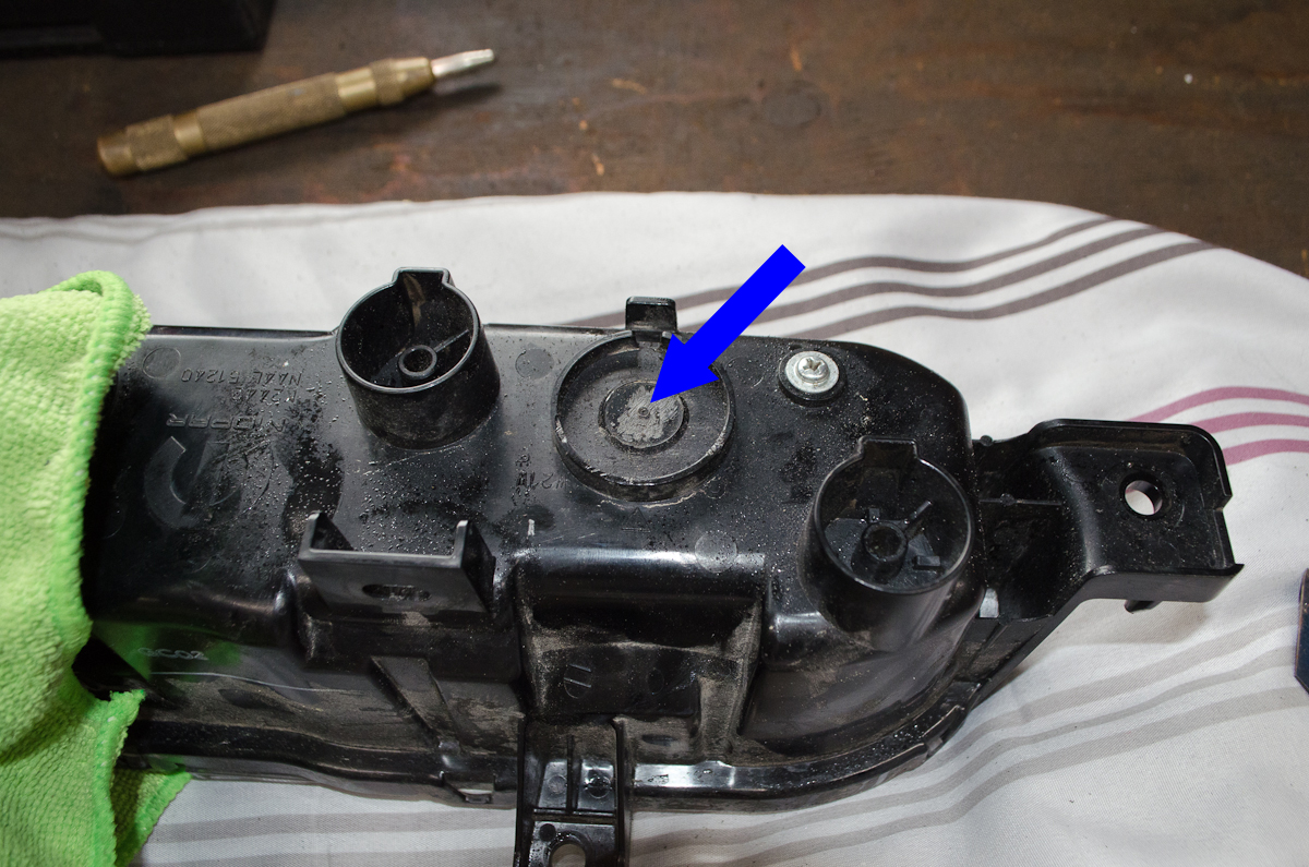 |
Location punched and ready to drill. | |
 |
I used a 9/16" spade bit in a cordless drill to drill the holes. | |
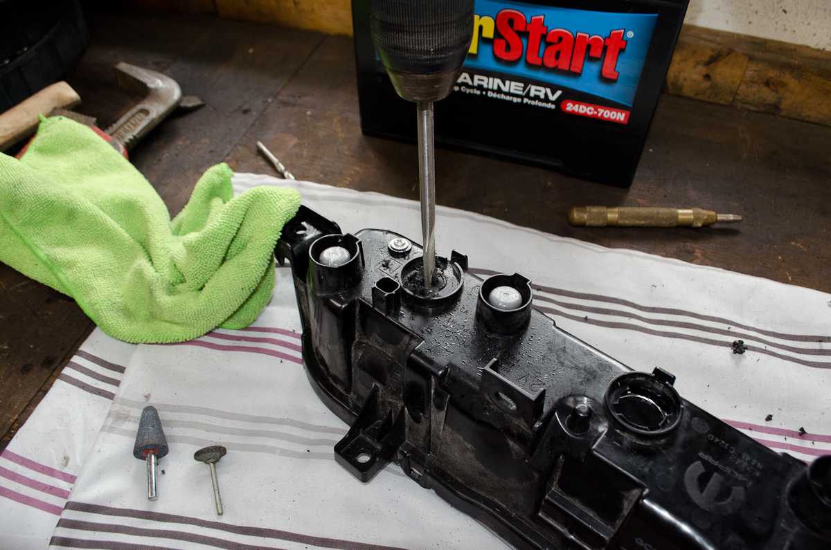 |
I began the drilling in this position, but before breaking through the plastic all the way, I held the housing the other way up to finish the drilling in order to minimize the amount of plastic drilling debris that falls into the light housing. If some does get into the housing, blow/vacuum/shale it out before continuing. |
|
 |
With the two holes drilled, insert the new red LED bulbs into the sockets and then... | |
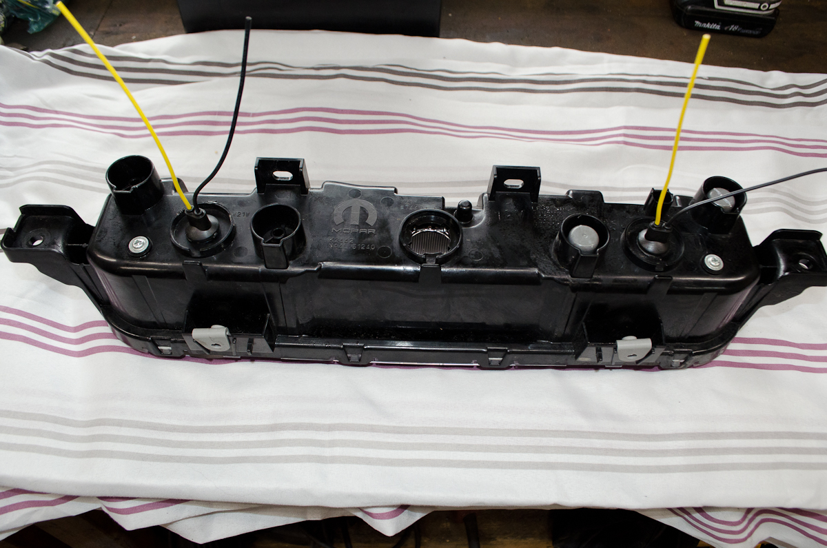 |
...insert the sockets into the holes. | |
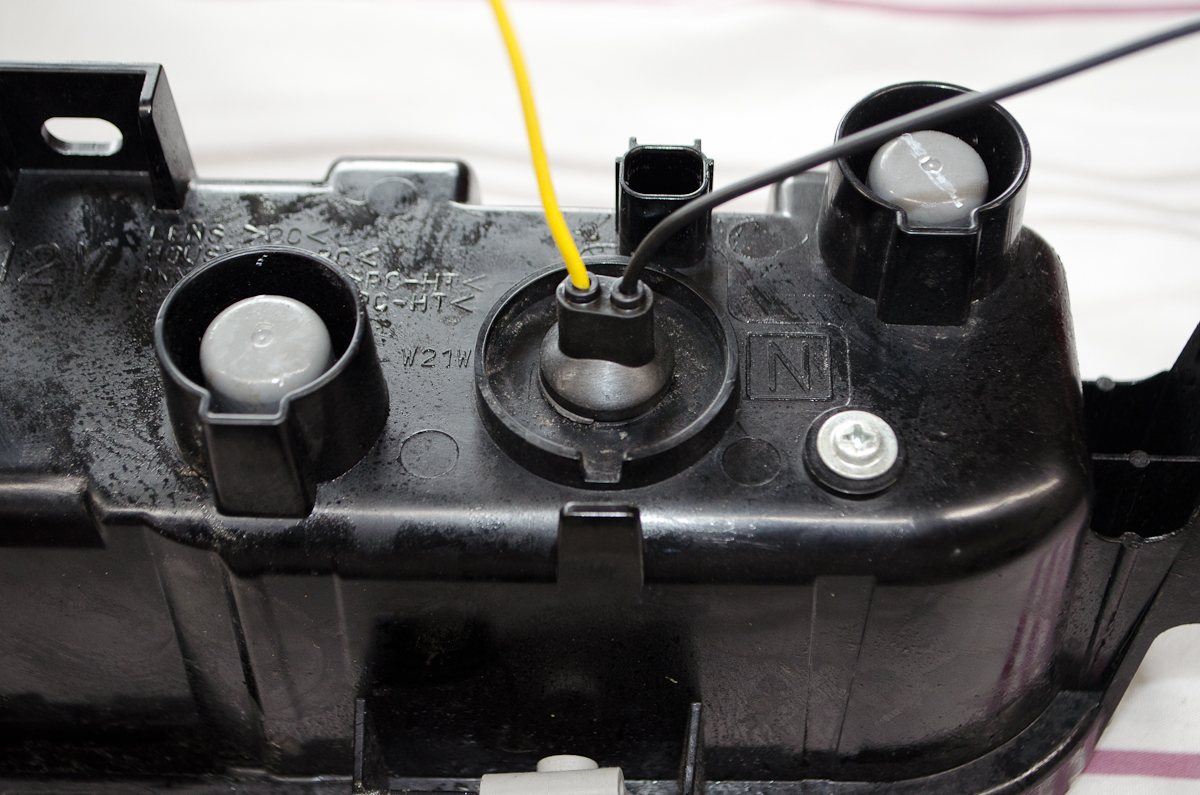 |
New socket installed with LED bulb. | |
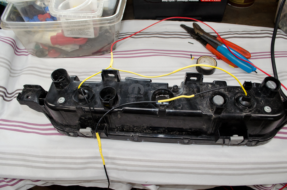 |
Next, connect the positive and negative wires from both sockets together and then to each add 48" (4 feet) of additional wire. I used red and black 16 gauge because that's what I had on hand. The LED bulb current draw is so small that almost any gauge will do...the factory wires are tiny...something like 22 gauge I think. I chose to solder the wires together and cover them with heat-shrink tubing and then taping them with electrical tape. You could use some other method, like crimp-on fittings, but whatever you do, make sure the connections are secure and weatherproof. |
|
 |
This is the grommet into which I cut a small slit with a sharp utility knife so I could run the wires from the new sockets into the trunk of the car. I ran the wires through the grommet and then took the assembly, wires, and grommet under the car, fitted the assembly into place, re-installed the 6 mounting screws, re-connected everything I had previously disconnected, and then pushed the grommet into place from underneath the car. Then I used a few zip ties to keep the wires secure and tidy. |
|
 |
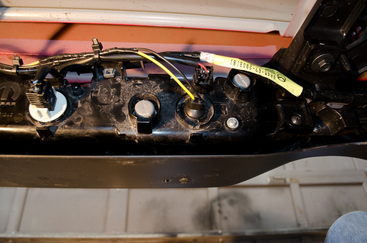
Here's the finished product from under the car. If I was to critique my own work I would say I should have taped the new wires a little further (red arrow) and the wires to the right socket are a little short/strained. |
|
 |
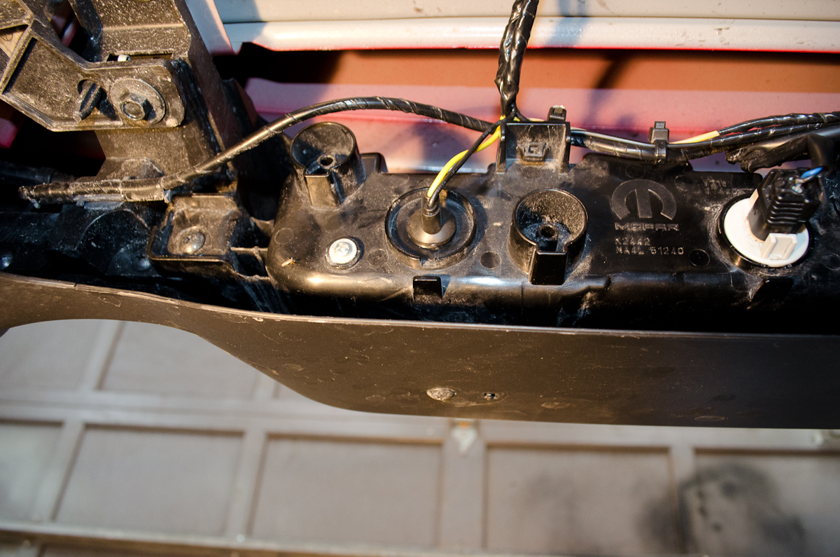
Left side completed. | |
 |
Right side completed. | |
 |
Finished under the car, it's time to complete the wiring in the trunk. First I added some silicone sealant to the grommet where the wires come through to keep it water-tight. |
|
 |
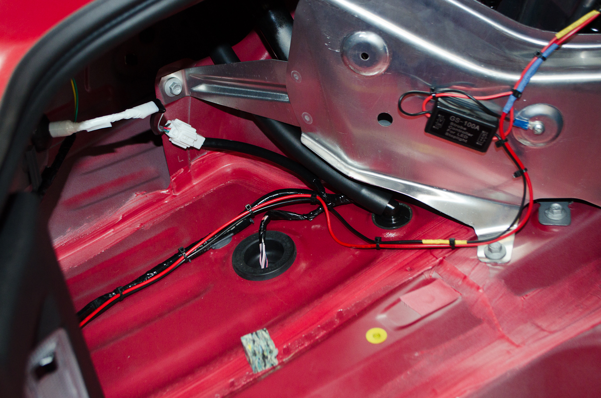
Next, locate the wiring that powers the CHMSL. | |
 |
I undid the electrical connector to give me some room to work, and then stripped back the black wiring sleeve to give me access to enough of the wiring to work with. | |
 |
The wire we need to cut and tap into is the red wire. | |
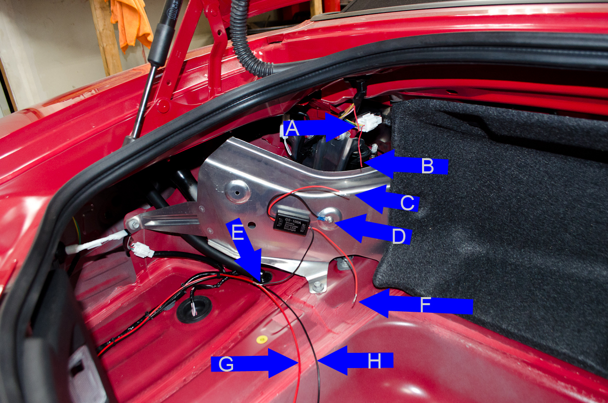 |
Here's the run down on the wiring: A - factory red wire going TO the CHMSL. |
|
 |
Make the connections as follows: F to G and A E to H C to B D to chassis ground |
|
 |
Once again, I soldered the wires and used heat-shrink tubing to cover them. | |
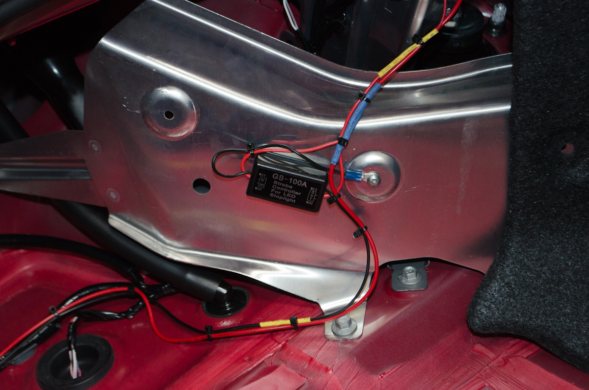 |
Not wanting to drill any holes in the car, I used an existing hole for one of the plastic rivets as my ground connection point. Obviously, I'll have to do without that one plastic rivet. You could alternatively use another connection point or drill a new hole. | |
 |
I tidied up the wire with some zip ties. | |
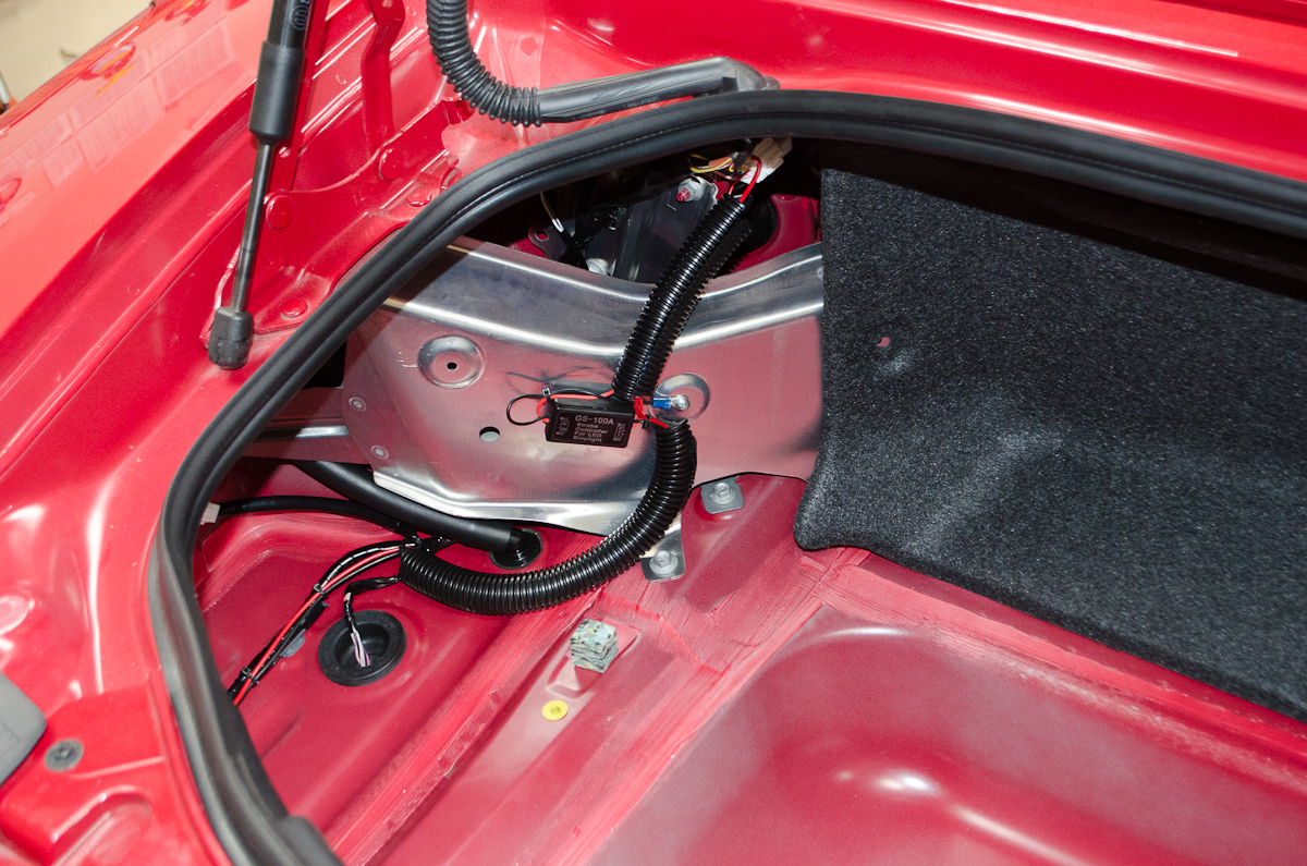 |
And then covered the wiring with some loom where it was anywhere close to any sharp edges. | |
Finally, re-install the two trunk-liner panels with the plastic rivets, reconnect the negative cable to the battery, and you're all done. Here's what the result looks like, day and night (apologies for the poor focus and bad colour-rendition of this video, but you get the idea):
|
||
|

