 |
The Cooling Bible By Bill "BillaVista" Ansell |
IntroductionThe cooling system – deceptively simple yet devilishly complicated. Like many things – your rig’s cooling systems is one of those things that seems simple, that most people think they understand, but which, behind the scenes, is actually a lot of fairly complicated stuff working together in a fine balance. Or not working together well – which is often the problem. |
|
In reality, “under the hood”, cooling systems contain a lot of pretty sophisticated engineering – laws of thermodynamics, pressure, turbulent and boundary-layer flow, aerodynamics, etc. As a result, because cooling seems simple, even though it isn’t, a LOT of misinformation and tenacious long-lasting myths exist surrounding it. So, let me get this out there – designing a complete cooling system is no easy task – especially if it’s for a high-performance rig that’s run hard. It takes a lot of know-how. So what are you to do? Well, the easy and obvious answer is to enlist the help of true professionals, like Griffin Thermal Products. You call them up, explain what kind of vehicle you have and what you want to do with it, and they will design, build, and supply what you need. These guys really know their stuff – they do everything from OEM, racing, off-road, & high performance, to industrial, locomotives, and aircraft. So if you have the means, and you just want results – skip to the end of this article, ogle the pretty pictures, then simply call them up and order your own. But – you don’t necessarily have to engineer your system to build something that works. As much as there is rumour and myth – there are also many tried and true approaches, many well-tested components, and many rules of thumb that DO work. The trick is – telling them apart. So, for those interested in a little more technical detail than just whom to call, that’s what this article will attempt to do – sort the myth from the truth and present some solid tech to help you down the road of putting your own high-performance cooling system together. At the very least, it will help you have a more productive and meaningful conversation with the experts at Griffin when you do call them to order what you need. Contents
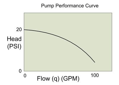
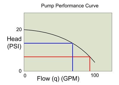
Physics and ChemistryIn this article I'm going to forgo too much detail in terms of physics, equations, and laws of thermodynamics - they get pretty complicated pretty quickly and will bog most of us down. Having said that, there are a few basic "laws" we should just remind ourselves of - because they crop up time and again and keeping them in mind will help keep us from making mistakes or falling prey to those ever-present myths that surround cooling systems. 1) Metal, engine components, fluids and gasses all expand when heated. 2) Heat rises - hot fluid will rise in a system and cooler fluid will descend. 3) Air or vapour is lighter (less dense) than liquid and will rise to the top of any closed system. 4) Liquids are incompressible. 5) Substances can change state between liquid and gas (vapour). Boiling water (a liquid) turning into steam (gas) is an example of this. When exactly this change of state occurs, depends on the temperature and pressure of the liquid. The greater the pressure a liquid is under, the higher the temperature it boils at (turns from liquid to vapour). 6) Heat spontaneously transfers from hotter objects to cooler objects. The rate at which this transfer occurs depends primarily on the difference in temperature between the two (the delta-T). When the difference is great, the transfer occurs extremely rapidly. As the temperature difference decreases - the rate of heat transfer decreases exponentially. This fact is an expression of Newton's Law of Cooling and understanding it is critical to dispelling one of the greatest and most-often quoted myths surrounding cooling systems. A good example of this law can be seen when quenching a red-hot piece of steel in a bucket of water. At first, the temperature difference (delta-T) between the red-hot steel and the water is huge - therefore the initial heat transfer occurs at a great rate - the steel initially cools very fast - almost instantaneously. However, after this initial cooling, the delta-T is much smaller, so the remaining cooling occurs much more slowly. If you removed the steel after a second or two - it has cooled a lot - but it will still be warm. To continue cooling the steel to the temp. of the water, you have to leave it in there quite a bit longer - because as it cools - the rate of cooling continually decreases as well. In short - initial cooling is fast, but subsequent cooling occurs more and more slowly until cooling that last little bit takes a long, long time. Remember this - we'll come back to it. Cooling System BasicsA vehicle's cooling system is designed to do one thing - maintain the engine at the proper operating temperature. Note that I didn't say the purpose is just to "cool the engine". This is one of the first and most often overlooked aspects of a cooling system (which isn't helped by the name). Yes, it's possible to "overcool" an engine, and doing so can be almost as damaging as allowing it to overheat. This is because all engines are designed to operate most effectively and reliably at a certain temperature. This normal operating temperature takes into account internal clearances, oil viscosity (which varies with temperature), and combustion efficiency (which affects power, economy, and emissions). Too hot, and critical clearances are lost, oil breaks down, pre-ignition occurs, metal composition is changed, parts start to weld together and severe damage occurs. Too cold and combustion is incomplete, power production is reduced, emissions are excessive, economy suffers, and oil never reaches the proper temperature and therefore viscosity and is therefore too thick to provide proper lubrication - especially between critical surfaces like main and rod bearings. To be fair - the majority of the work the cooling system must perform is to remove from the engine heat produced by combustion - but a good cooling system must also be designed to allow the engine to come up to proper operating temperature as quickly as possible and then keep it there. Power makes heat. The more power the engine creates, the more heat it creates. As wonderful as they are - spark-ignition internal combustion engines are actually pretty damn inefficient beasts. A typical engine will loose more than 30% of the power it produces to heat production. That's a LOT of heat! Peak combustion chamber surface temperatures can exceed 500°F and the temperature of the combustion itself can exceed 3000°F. In fact, if you were to run an engine without a cooling system, even for only a short time, the temperatures produced could quickly melt the piston and fuse it to the cylinder. Clearly then, cooling is very important in order to keep this and other component failures from happening. But that's not all - even in a working engine with a cooling system, well before total component melt down occurs, if the cooling system isn't up to scratch, excessive heat in and around the combustion chamber will cause pre-ignition and detonation - both of which have major negative affects on power production, efficiency, and longevity of the engine and can cause plenty of damage of their own. The reason I'm pointing this out is two-fold: First - so you have a good appreciation for how much the cooling system does (and therefore why it's worth investing the time and money into getting it right). Secondly, so you understand that, just because your engine isn't blowing steam out the rad cap or melting pistons - doesn't mean that it's working optimally and couldn't use some improvement. Same goes for the guy down the street (or on the internet)- who's advice you're considering taking - just because he says "I just plugged the steam ports and haven't had any problems" doesn't mean his cooling system works well or that it won't cause problems down the road. Pump Performance Curve and Total System Pressure DropFluid flows because of pressure. It naturally flows from regions of high pressure to regions of low pressure. This basic theory explains everything from how airplanes fly to weather patterns. When fluid flows through a pipe, like a garden hose, there is friction between the fluid and the inside walls of the pipe. This friction creates pressure drop. Pressure is what causes the fluid to flow. If the pressure drops to zero before the end of the pipe, the fluid will not come out the end - it will just stop as if a valve was closed. Therefore, in order for fluid to flow through the pipe, the pump must be able to generate enough pressure to overcome, or equal, the total pressure drop in the pipe. Take our garden hose as an example. Say we have it hooked up to a 10 PSI pump, it is 20' long, and has a sprinkler on the discharge end. When we open the tap, a certain flow will come out the sprinkler. The pump creates pressure, and that pressure causes the water to flow towards a region of low pressure - in this case ambient atmospheric pressure outside the sprinkler. If we add a 100' length to the hose we add a whole bunch of friction and therefore increase the pressure drop in the hose. If the pump still continues to produce only 10 PSI we will get reduced flow and therefore reduced output out the sprinkler. Ultimately, if we add enough hose, the pump's output pressure will no longer be able to overcome the total pressure drop and nothing will come out the end. If we connected a hose 5 miles long to the tap on our 10 PSI pump, nothing would come out the end. If it helps, we can think of the total system pressure drop as "backpressure" against the pump - backpressure against which the pump must pump in order to create flow. Now, these same rules apply equally to a complex series of pipes, tubes, passageways, manifolds, and restrictions as they do to a simple single pipe. Pump outlet pressure must equal total system pressure drop for flow to occur. Pump outlet pressure is referred to as "head". Therefore head must equal backpressure. Simple enough, right? In the case of our cooling system, it is just that - a complex series of pipes, tubes, passageways, manifolds, and restrictions. All the various components induce some pressure drop in the system - some large, some not so large, but they all add up and the pump must be able to overcome the total. In addition, the cooling circuit is a closed system, meaning the output from the pump returns to become the inlet to the pump - the fluid flows in a circular route so that if the pump's head cannot overcome the backpressure, flow stops and there is nothing returning to the pump for it to continue pumping. An automotive water pump is a centrifugal, non-fixed-displacement, vane-type pump. The pump creates the pressure and flow required to circulate the coolant. The pump must produce enough pressure at its outlet to overcome the restrictions in the cooling system. In other words, the coolant passages in the rad and engine create a certain amount of backpressure. The pump must be able to generate sufficient head in order to pump the coolant. Now, pressure and flow are directly related. Depending on its design, construction, and specifications a pump will produce a certain head for a given flow. Stated differently, a pump will be able to produce a certain flow rate for a given amount of backpressure (or resistance in the system). As we mentioned, in pump specification terms, the pressure a pump creates at its outlet is called "head". For centrifugal automotive water pumps, as head goes up, flow goes down. This makes sense - all we're saying is - the greater the resistance to flow in the system, the greater the head the pump must produce, and the less flow the pump will create. If you draw a graph of any particular pump's performance in this regard, it is called the "characteristic performance curve" of the pump, or sometimes just the "performance curve". Here is a completely hypothetical example curve, just to illustrate the point. The values are not intended to be representative of typical or actual pump performance.
As you can see, the pump creates maximum head at zero flow. This makes sense - if we block the pump outlet (zero flow) the pump will create its maximum pressure. Alternatively, we can say the the pump is able to flow the most when the head (or the backpressure of the plumbing system) is the least. The pump will always operate somewhere on its performance curve. Therefore, if backpressure due to restrictions in the cooling system goes up (total pressure drop increases), pump head must go up and therefore pump flow goes down. This is important to keep in mind as we generally want to maximize flow for the most efficient cooling (assuming we have the required airflow to match high coolant flow). True cooling system engineering would include mapping pressure drop throughout the system, because this pressure drop affects more than just flow. As we shall discuss momentarily, pressure is also important in determining the boiling point of the coolant and in maintaining consistent and complete contact in the block and cylinder head passageways between the coolant and the hot engine parts. In addition, since pressure drop is least at the pump outlet and increases through the system restriction to a maximum at the pump return, this means actual system pressure is greatest at the pump outlet and least at the pump inlet. Knowledge of system pressure at certain points is an important consideration in determining optimum location of certain components like the rad cap, steam vents, and surge tanks, as we shall soon see. Since measuring and mapping pressure drop throughout the system is beyond the capability of most enthusiasts, for design and plumbing consideration, generally the cooling system is simply divided into the "high pressure" side and the "low pressure" side. |
|
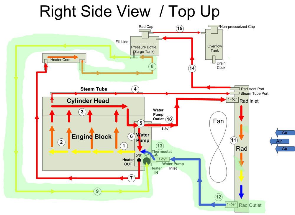 |
The areas where restriction are high are said to be the "high pressure" side of the system, and areas where restriction to flow are low are said to be the "low pressure" side of the system. Essentially, the low pressure side is the area after the heater and rad core up until the return (or inlet) side of the water pump. In this pic the low-pressure side is shaded in green, everywhere else is considered the high pressure side. In general, the radiator tank after the core and the return line to the pump, along with the return line from the heater are the low pressure side. Don't worry about all the other details in this pic at this time, we'll cover them in good time. |
|||||||||||||||
Cooling System ComponentsThe following are the basic components of any cooling system and so this section applies to any vehicle or any engine. Following this we'll have a look at some more specific GM Gen III/IV V8 ("LS") cooling system tech. |
||||||||||||||||
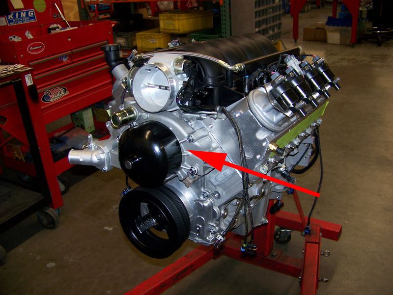 |
Water Pump The water pump is a centrifugal-type non-fixed-displacement pump that circulates the coolant through the block and heads where it collects heat from the engine, and then through the radiator where it is cooled by air flowing through the rad. The simple rule with water pumps is - the higher the flow the better. The reason for this will become clear later (and don't ever listen to anyone who says a water pump can flow too much and not let the coolant cool down in the radiator - pure myth. But I'm getting ahead of myself). |
|||||||||||||||
 |
Coolant The coolant is the liquid lifeblood of the system. Its job is to absorb the heat from the engine, and then give-up this heat in the radiator as air flows over the vanes attached to the tubes that carry the coolant. Coolant must also condition and lubricate the seals in the water pump and, in all but the most rigorously maintained race vehicles, inhibit corrosion in the many passages of the cooling system. Finally, in vehicles run in colder climates, the coolant must not freeze. An entire separate article could be written around the debate over coolant types and brands. Rather than get into all that here, let's just stick to the basics. |
|||||||||||||||
Heat (or heat energy) is measure in units called British Thermal Units (or BTUs). A BTU is the amount of energy required to raise 1 pound of water 1°F. Without knowing anything about thermodynamics, it's obvious that the best coolant is one that can absorb and give off the most heat energy per degree of temperature change it experiences - in other words it should be able to absorb and carry away a lot of heat energy without getting too hot itself. This property is called "specific heat". A liquid's specific heat is the number of BTUs it takes to raise the temperature of one pound of that liquid 1° F. In other words, the higher a liquid's specific heat, the more heat energy it can absorb per degree of temperature rise. We want the coolant to absorb a lot of heat energy while suffering the lowest temperature rise possible - that way the coolant can carry away the most heat without getting too hot itself and boiling. If the coolant boils it becomes a vapour (gas) and is now useless to us. It turns out that plain old distilled water has the highest specific heat of all liquids commonly used for coolant. Water has a specific heat of 1 - meaning one pound of water can absorb 1 BTU for a temperature increase of 1° F. A 50/50 Ethylene Glycol / water mix has a specific heat of 0.5, meaning it takes only 0.5 BTUs to raise the temperature of 1 pound Ethylene Glycol / water mix 1° F. A 50/50 Propylene Glycol / water mix has a specific heat of only 0.3. Therefore, it takes twice as much heat to raise a pound of water 1° F than a 50/50 Ethylene Glycol mix; and over three times as much heat to raise a pound of water 1° F than a 50/50 Propylene Glycol mix. Ultimately, what this means is that straight water can carry away 50% more heat than 50/50 Ethylene Glycol mix and 70% more heat than 50/50 Propylene Glycol mix per degree per unit volume. Of course, how much heat a liquid can absorb without boiling is also a function of the pressure acting on that that liquid. The boiling point, also called "vapour point" is that temperature where a particular liquid turns to vapour - which we don't want. Now - the more pressure a liquid is under, the higher its boiling point. This is precisely why cooling systems are pressurized. In the case of water, our most efficient coolant, we all know that at atmospheric pressure it boils at 100°C or 212° F. However, if we pressurize the water, its boiling point increases as follows:
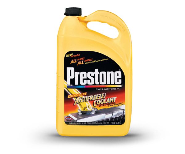
We can see from the chart that, if we were running straight water, un-pressurized, it would boil at 212° F - which is no good as this is perilously close to the designed normal operating temperature of many modern engines. However, if we pressurized that water to even only 10 PSI, it wouldn't boil until 239° F. Many modern vehicle cooling systems are pressurized to 14-18 PSI, high performance systems to 22-24 PSI, and racing systems to 29-31 PSI. At the extreme end of the scale, Formula 1 race cars pressurize the coolant to as much as 50psi and have engine operating temps of about 265° F. Now, at atmospheric pressure, both Ethylene Glycol and Propylene Glycol have higher vapour points than water, and this trend continues at higher pressures. That means they will not boil until they reach higher temperatures which in turn means a) that they can continue absorbing and transferring heat at temperatures higher than water is capable of and b) that they provide a greater safety margin against coolant boiling. Commercial coolant mixtures also have a lower freezing point than water and contain additive and conditioning packages to lubricate and inhibit corrosion in the cooling system. Ultimately, which coolant to use will depend on your circumstances. For most, the benefits of an Ethylene Glycol mix or perhaps even a Propylene Glycol mix outweigh its lower efficiency. Of course, rather than run the normal OEM-recommended 50/50 mix, one can always custom tailor a mix to gain some of the advantages of a coolant mix while retaining as much of the efficiency of straight water as possible (e.g. a 75% water / 25% Ethylene Glycol mix). If you do - be sure to check that the vapour point and freezing point of the custom mix meets your system's needs. This is normally indicated in a little table on the bottle. However, for those running vehicles at the top edge of performance that see rigorous regular maintenance and are never subject to freezing temperatures - straight distilled water is undoubtedly the most effective liquid to use for coolant. Many folks who do run straight water will also add a small bottle of seal conditioner / corrosion inhibitor, such as Prestone Super Anti-Rust, to keep the water pump happy. |
||||||||||||||||
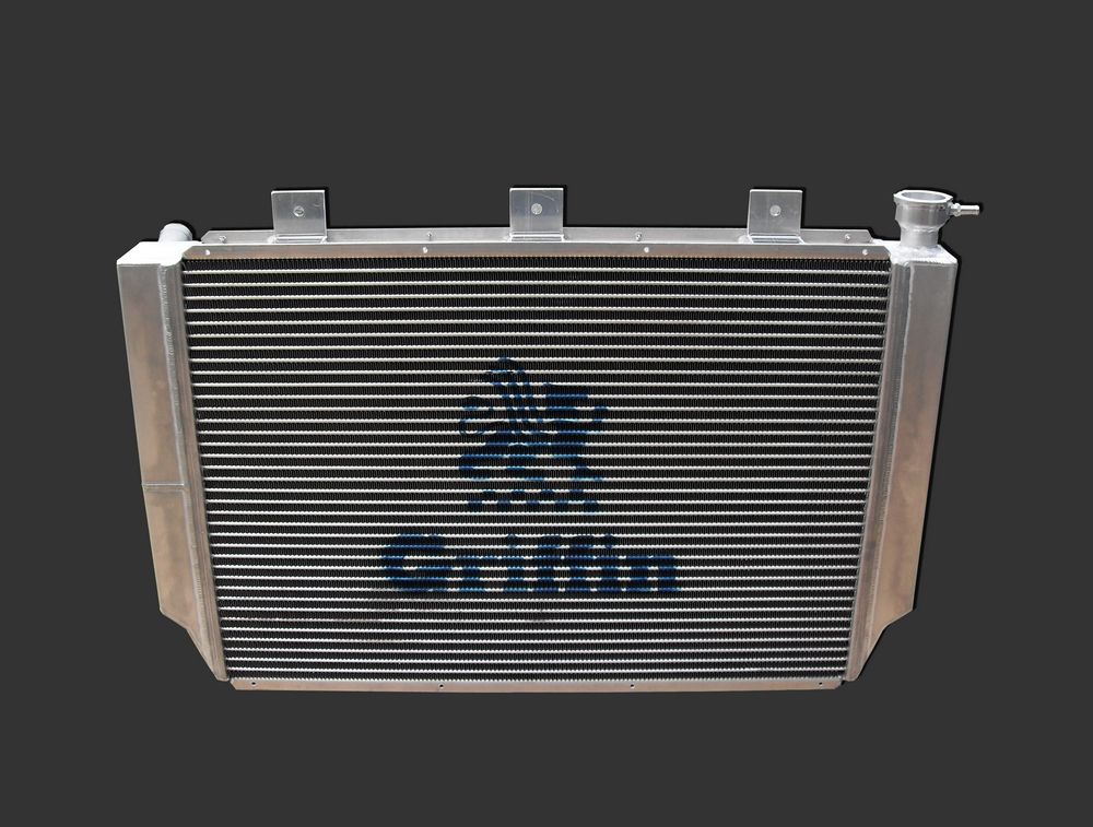 |
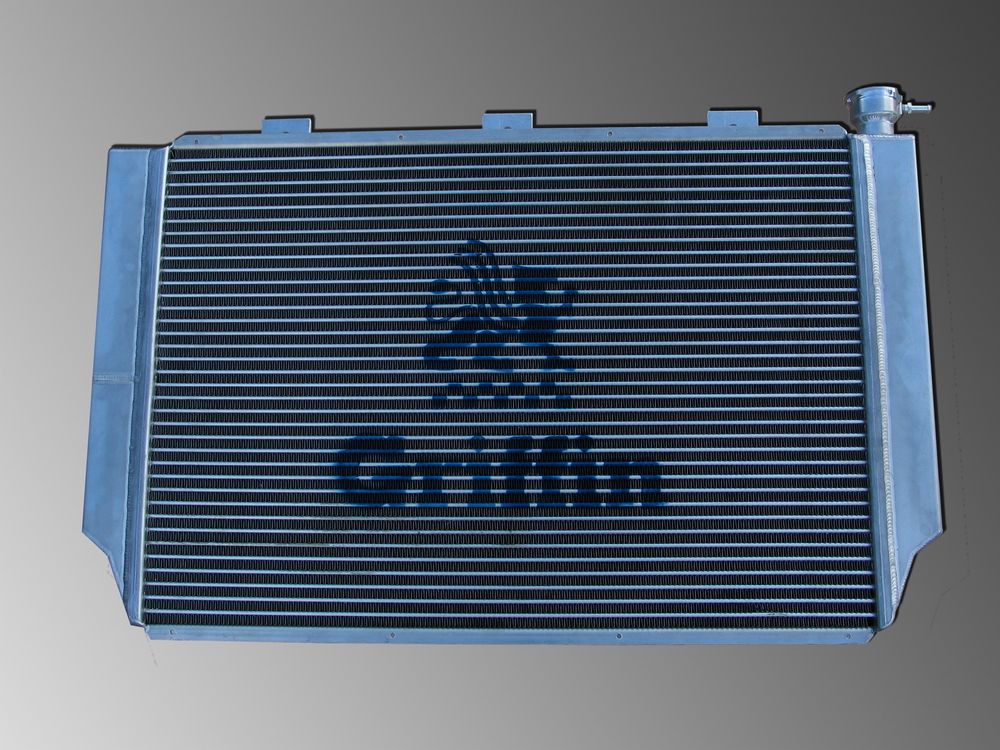
Radiator The heart of the system, a high-quality, appropriately-sized radiator is the single most important component in the cooling system. We'll look at how to spec a radiator, who makes the best, and what the best features are, in great detail later in the article. The short story is: Get the biggest aluminum radiator from Griffin Thermal Products that you can possibly fit!
|
|||||||||||||||
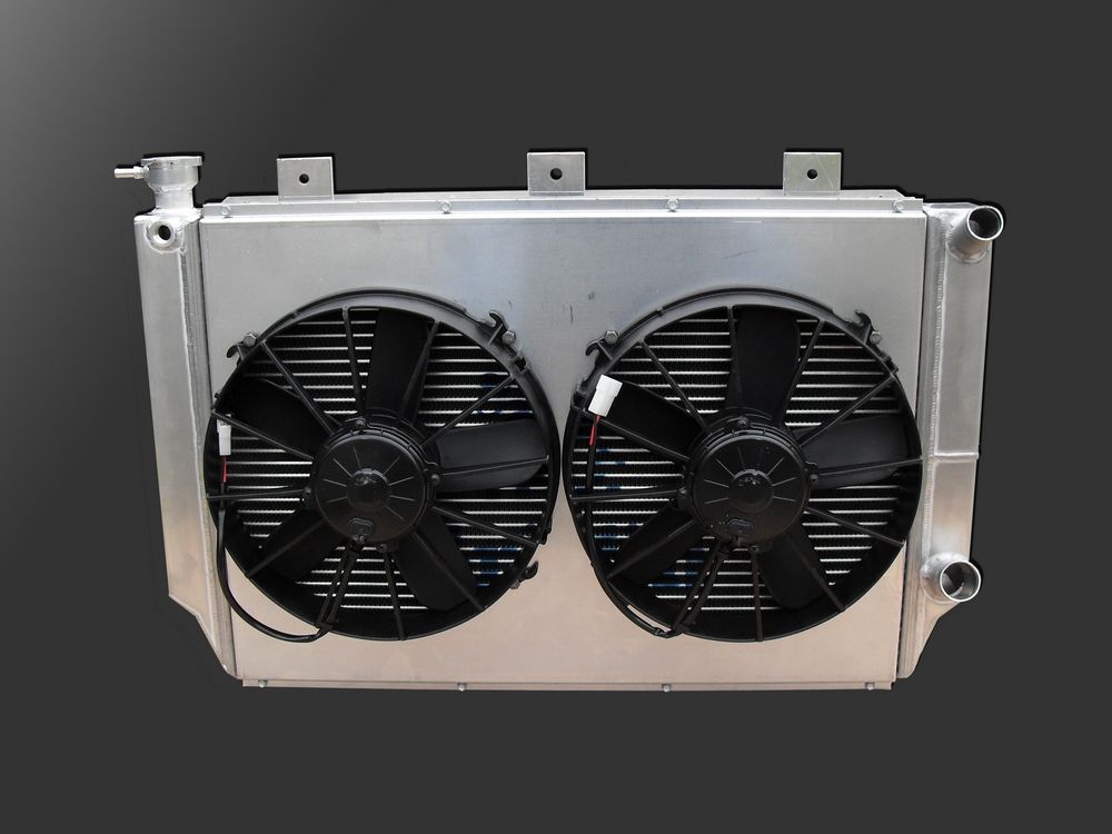 |
Fan(s) and Shrouds Of course, a radiator is no use without a fan or two to pull air through it. By far the best fans are electrical "puller" fans - and the best of those are made by SPAL. Electric fans offer superior control, flow, mounting flexibility, and a host of other options not available from mechanically driven fans. In recent years, the popularity of front-wheel-drive cars with their transversely mounted engines that obviously must use an electric fan has led to major advances in electric fan performance and computer control that older mechanical fans can't match. |
|||||||||||||||
The only real choice for a performance cooling system is a "puller" fan - one that is mounted behind the radiator (in relation to the airflow) and sucks the air through the radiator. They are far more efficient than "pusher" style fans that mount in front of the radiator and push air through it. All fans should be shrouded. Without a shroud your valuable airflow is dramatically reduced and all manner of complicated aerodynamics can go on, essentially leaving your expensive performance rad and fan combo stifled and unable to do its job before it had a chance. |
||||||||||||||||
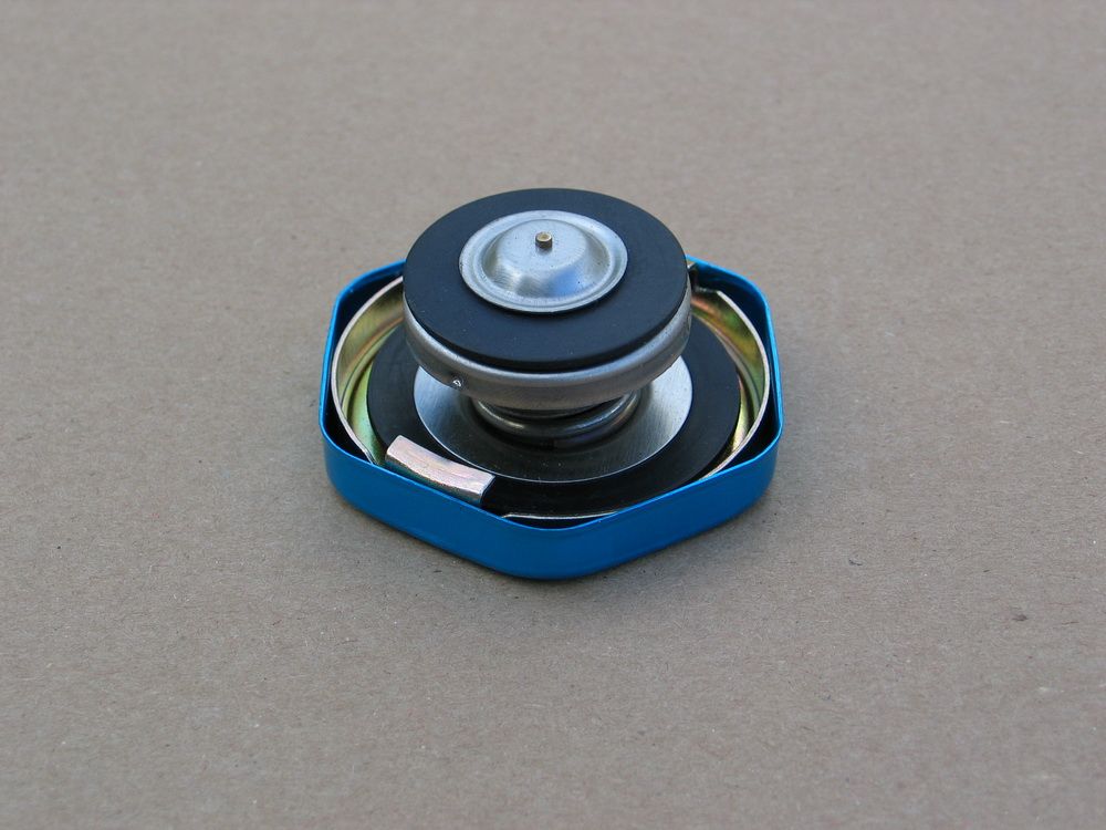 |
Radiator Cap The radiator cap is the "pressure relief valve" of the cooling system. It consists of a pressure-sensitive spring-loaded seal assembly that seals the cooling system from the atmosphere and thereby allows it to build the all-important pressure we were just talking about. In addition to raising the vapour point of whatever coolant is used, system pressure is vital for keeping coolant in contact with the metal surfaces of the cylinder heads and block. Consistent contact between the coolant and the engine passageways, particularly in the block and heads, is vital to prevent localized boiling or steam pockets in the combustion chamber areas of the cylinder heads. |
|||||||||||||||
Also, block pressure must be adequate to ensure uniform coolant distribution from the front to the rear of the engine. Low pressure can often result in insufficient cooling around the rear cylinders - which is why certain engine problems always show up first in the rear cylinders. Steam pockets or localized coolant boiling can occur when excessive heat is generated (because of a lean condition, excessive ignition advance, or faulty cooling system) causing the coolant to reach its vapour point and spontaneously change state from liquid to gas - in other words - boil. This is sometimes referred to as "flashing to steam". The problem usually occurs first in the combustion chamber area because it is the hottest region. When this happens - a vicious cycle begins - cylinder head hot spots cause steam pockets - steam pockets tend to "stick" in the highest area (the head) - steam cannot contribute to cooling and displaces much needed coolant - the excessively hot cylinder head experiences detonation and/or pre-ignition - which in turn creates excessive heat which causes hot spots and localized coolant boiling and steam pockets to form and so on. Adequate system pressure (along with a properly functioning cooling system and properly tuned engine) helps ensure that the coolant's boiling point is sufficiently high that the formation of steam does not occur and the cycle cannot begin. Keeping the coolant under pressure also helps to prevent cavitation in the water pump. The pressure in the cooling system comes from two sources. The first is from the action of the water pump pumping the coolant through the restricted passageways and plumbing of the cooling system. Secondly, since the cooling system is a closed and sealed system and liquids are both incompressible and expand when heated, pressure in the system results from the normal expansion of the coolant in the system as it heats up. Normally 12-17 PSI pressure is created when the coolant expands as a result of going from ambient temperature to normal engine operating temperature. The radiator cap serves to regulate maximum system pressure. A properly functioning cooling system in good working order will not normally generate excessive pressure. But under certain conditions like excessive heat generation or component degradation/failure system pressure can build well beyond normal. If this pressure were allowed to build unchecked, eventually component damage would occur - including hoses blowing off, seals being blown, and damage to the pump and radiator and any other component not able to withstand the elevated internal pressure. To avoid this, a radiator cap (safety valve) is installed that is designed to open at a certain pressure. A calibrated spring normally holds a seal in place that keeps the system sealed and pressurized. However, if system pressure builds beyond the opening pressure of the cap, the spring force is overcome, the seal retracts from its seat, and the system is opened to atmosphere. When this happens, excess pressure and fluid volume is allowed to bleed off in a controlled manner to a recovery tank, through a small fitting located just above the seal seat. The rad cap also serves as the point of entry for filling the system with coolant and for bleeding the air out. The rad cap must be installed at the highest point of the system. Often this is on the radiator itself, but when this is not possible due to the position of the radiator (i.e. the top of the rad is not the highest point in the system), the rad cap may instead be installed on a pressurized surge tank, as we shall soon see. As we previously discussed, because pressure drop increases as the coolant flows from the pump, through the system, and back to the pump, system pressure is not equal everywhere. This is an important consideration in rad cap location. The rad cap operates on the system pressure at its location. If it were located in the highest pressure portion of the system (the pump outlet or radiator inlet), it would regulate system pressure based on that highest pressure, meaning pressure elsewhere (for example, in the back of the cylinder heads) would be something less than the rating on the rad cap. This could mean pressure in the critical engine passageways could be as much as 10 PSI or more lower than the rad cap pressure rating - which is not good for cooling performance. It's also difficult to accurately measure system pressure at all locations, so you probably wouldn't even know how low the pressure was in the cylinder heads with the rad cap installed in the high pressure side of the system. In other words, with this arrangement, you may install a 20 PSI rad cap and expect coolant boiling point to be 259° F, but actual pressure in the heads, where boiling would occur first, would be less - perhaps only 10 PSI, and therefore actual coolant boiling point would only be 239° F - some 20° F less than you think! For this reason, the rad cap must be located on the low-pressure side of the system - either on the appropriate rad tank or on a remote-mounted surge tank. Regardless of the location, the best advice is to run the highest rated cap the design and construction of the system will allow. For the dedicated seeking ultimate cooling performance, this may take some messy and risky trial and error - most often the result of a cap rated too high is a blown hose, but it could also lead to a cracked radiator. Some common values are: Stock: 14-18PSI The rad cap also has a spring-loaded valve that can open to allow coolant entry back into the engine - described below in the section on "overflow tanks". |
||||||||||||||||
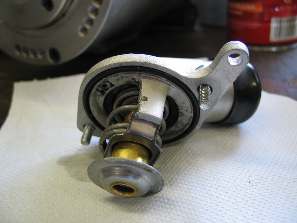 |
Thermostat The thermostat is the "brains" of the cooling system. Recall how we said that the job of the "cooling" system was actually to regulate or control the temperature of the engine to keep it as close as possible to the designed normal operating temperature at all times? It is the thermostat that accomplishes this.
|
|||||||||||||||
The thermostat is located in an area between the engine and the radiator. The classic small-block Chevy V8 located the thermostat on the "outlet" side of the motor, in the intake manifold. When cold, the thermostat was closed, and this prevented flow of coolant to the radiator. When the engine warmed up, the thermostat opened and coolant was allowed to flow to the radiator and back to the engine. The newer third- and fourth-gen GM V8's locate the thermostat on the "inlet" side of the motor - specifically in the inlet housing of the water pump. With this design, when cold, coolant is pumped through the rad, but is prevented from returning to the engine until the temperature of the thermostat has been reached, at which point the thermostat opens and the cooled coolant returns to the engine. Similar to a rad cap, a thermostat contains a spring-loaded sealing mechanism - but instead of reacting to pressure, it reacts to heat. Most thermostats do this with what is called a "wax motor". The wax motor is a cylinder containing a wax pellet that acts directly on the thermostat piston. As the wax heats up, and expands, it forces the piston to open the seal and allow coolant to pass. The Gen III/IV inlet thermostat location is designed to eliminate the following conditions / problems:
|
||||||||||||||||
 |
Overflow Tank All systems, regardless of whether they also use a pressurized "surge tank" or not, must use an overflow tank. Also known as an overflow catch tank, overflow bottle, catch can, expansion tank, or recovery tank the overflow tank has a simple installation and job. It merely connects to the "dry", outside, non pressurized area immediately below the rad cap but above the rad cap seal, so that in the event the rad cap opens due to overtemp/overpressurization, the hot coolant and gas that is expelled is collected safely. This pic illustrates the filler neck on my Griffin rad, where you can clearly see the outlet to the overflow tank above (or "on the dry side") of the rad cap seal seat. |
|||||||||||||||
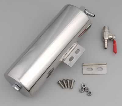 |
The overflow tank is not to be confused with a surge tank or coolant recirculation tank - though they do appear similar. The overflow tank serves no function in the normal operation of the coolant system. It only comes into play if there is an overpressurization and the rad cap opens, and then it only serves as a safe, environmentally responsible collection point for expelled coolant. If the system pressure reaches the cap’s pressure rating, the cap’s spring is compressed, forcing the valve open and allowing coolant to escape through the overflow tube to the overflow tank. After such an event, as the system cools it contracts, creating vacuum that opens the other spring- loaded valve, in the rad cap, allowing coolant in the overflow tank to be sucked back into the radiator. |
|||||||||||||||
The overflow bottle can be distinguished from the surge tank / recirculation tank in that:
The differences between the two will also become more clear once we get to the section on plumbing. |
||||||||||||||||
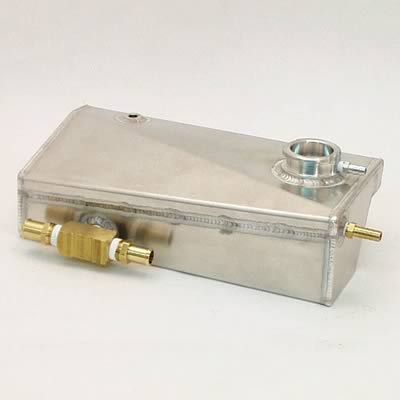 |
Surge Tank The surge tank is a completely different animal from the overflow tank. It is an integral part of the cooling system through which coolant continually flows. The surge tank also goes by many other names, adding to the common confusion between it and the overflow tank. You may see it referred to as a recirculating expansion tank, pressure tank, recirculation tank, coolant expansion fill tank, de-aeration tank, and others. A surge tank serves two purposes. First it allows for "remote mounting" of the rad cap in situations where the top of the radiator is not the highest point in the system. Secondly, it serves as a de-aeration chamber, allowing for continual and effective removal of any vapour (air or vaporized coolant / steam) in the system. |
|||||||||||||||
 |
How it does this we will examine in detail in the section on plumbing. For now, understand that, unlike the overflow tank, the surge tank is plumbed "inline" in the cooling system and therefore has coolant continually circulating through it, and is therefore a pressurized component of the system. Surge tanks may come in many different forms. The one pictured above is a "Corvette style" tank, and the one pictured to the left is a generic aftermarket one. |
|||||||||||||||
Regardless of its exact form, a surge tank can be distinguished from an overflow tank by the fact that:
It is also important to note that the surge tank does not take the place of the overflow tank - it is used in addition to the overflow tank. This can be seen in both the examples above where you can clearly see the fitting in the filler neck (the overflow tube) that connects to the overflow tank - exactly the same way it does when the filler neck / rad cap are mounted directly to the radiator. |
||||||||||||||||
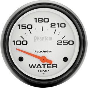 |
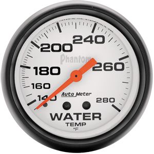
Temperature Gauge Of course, it's important that you be able to monitor the performance of your cooling system, so a high quality gauge is a must. Not being an article on gauges and instrumentation, I won't go into all the details of selecting gauges here, except the following important considerations. From my aviation experience, it is a good idea to have the normal operating condition of all gauges appear at a consistent location on the gauge, normally at the 12 o' clock position. This way, a quick glance is all that is required to verify that all "temperatures and pressures are in the green" (meaning all OK). |
|||||||||||||||
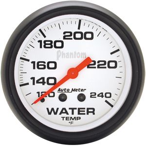 |
Different gauges have different temperatures at the 12 o' clock position, as can be seen from the accompanying photographs. Depending on the designed operating temperature of your engine, when selecting a gauge, along with other considerations you should consider selecting a gauge that displays the correct operating temperature at the 12 o' clock position. The gauges pictured here appear in order from coolest to warmest in terms of the temp indicated at the 12 o' clock position; in order 180° F, 200° F, and 230° F. |
|||||||||||||||
 |
This leads me to the other point. We often talk, as I have done here, as if the temperature on the gauge were the temperature of the engine, but this isn't entirely accurate. What the gauge reads is the temperature of the water, or coolant, at the position of the sensor or sending unit - it's even marked right there on the gauge "WATER TEMP". This can be an important consideration when selecting where to mount the sensor or sending unit. We must also understand the distinction between this water temp and the actual temp of the engine. |
|||||||||||||||
| Coolant temperatures do not accurately reflect actual metal temperatures in the engine. The metal can be several hundred degrees hotter than the adjacent coolant.
This means, depending on the gauge sending unit location, coolant temperatures may read "normal" while the actual temp of the cylinder heads, for example, may be excessive. Therefore, the location of the gauge's sending unit or sensor must be chosen carefully
- somewhere in the cylinder head is often a good choice.
Assuming the gauge sending unit is properly located, an engine typically runs most efficiently when the coolant temperature is kept around 200° F. This comes back to maintaining the proper operating temperature again. At this temperature, the combustion chamber is warm enough to completely vaporize the fuel mixture for improved combustion, and the oil’s viscosity is at the right point so that it can properly lubricate the engine and present minimal parasitic drag. An engine that is too cold is no good! Do not try to design your cooling system so that your engine runs all day at 160°F! For most "normal" engines, 250°F is about the greatest water temp indication you should tolerate. Beyond this and the engine should be shut down or allowed to idle until it cools down. Incidentally, this is another advantage to electric fans. Because an electric fan can continue to run when the engine is not running, and because hot coolant will rise and be replaced by cooler coolant, and because the rad inlet is at the top and the engine inlet at the bottom - coolant will circulate and you can actually cool the engine even when it isn't running. |
||||||||||||||||
How to Build a Killer Cooling SystemOK, so now we know all the basics - what the parts are, what they do, how the system flows and is plumbed, what pressure does for us, etc. Now - what distinguishes a good, capable cooling system from a lousy, inadequate one? How do you begin to design or build a cooling system for your rig? The quick answer is, you should maximize:
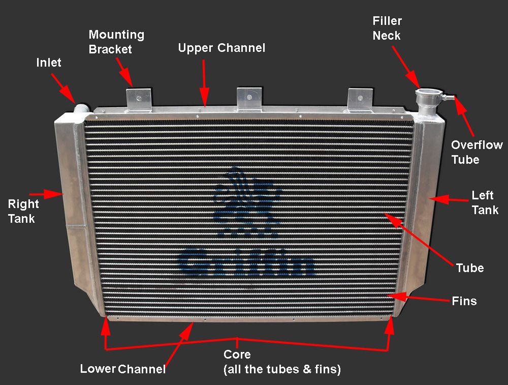
Here are Griffin's "10 Commandments for Maximum Cooling". I agree with them all (I'm sure they'd be relieved to hear that ;-) as they apply to most normal, street-driven vehicles. For race or other high-performance vehicles the only exceptions I would take are with regards to the the pressure of the rad cap and the percentage of Ethylene Glycol or Propylene Glycol in the coolant, as we have discussed. Now we will cover some tech details and advice on selecting the main components for any cooling system, but focusing especially on a cooling system for an offroad rig powered by a Gen III or IV GM V8 The RadiatorFirst - let's just go over the main parts of the radiator, because, as usual, some folks insist on using terms loosely or incorrectly which can lead to confusion.
The tanks are connected by the tubes. Coolant enters the tank with the inlet port, and flows between the tanks via the hollow tubes (which are actually very wide and thin in cross section, not round). Sandwiched between the tubes are the fins. The part that forms the actual joint between the rows of tubes and the tanks is called the header - you can't distinguish it in this pic, but you will see a pic of the header later when I show you a Griffin Rad being built. The combination of all the tubes and fins together is called the core. Thus, the two major components are the core and the tanks. The core will always have many rows of tubes between the top and bottom of the rad, but it may also have one or more rows of tubes (from front to back) for each "row" between the tanks. You can't easily tell this, because the rows of tubes would all be one behind the other. Some folks interchange the word "core" for "tubes" so that you may hear them say they have a "3-core rad". What they mean is that the core of their rad uses 3 rows of tubes, one in front of the other, for each "row" between the tanks - not that the rad has 3 complete cores!
There is no one magic formula to spec'ing, buying, or building a top quality radiator. There are many complicated inter-related factors at play and designing and building a great radiator is both art and science. Fortunately, this is something Griffin Thermal Products are very, very good at. Keep in mind, as you read the following considerations that a radiator is only as good as the sum of its parts, that there is a lot more to a quality radiator than meets the eye, and that there are few hard-and fast rules, despite what some would have you believe (for example, you can't say that a 3-row rad is always better then a single-row rad.) As you read this section, keep in mind that the job of the radiator is to expose as much hot coolant as possible to the inside surfaces of the rows of tubes that connect the radiator tanks. Heat is thus transferred from the coolant to the tubes. From the tubes, the heat is transferred to the fins. Airflow passing over the fins then dissipates the heat into the air. That said, here are some of the factors to keep in mind when selecting or spec'ing a radiator: MaterialThere is only one choice of material for a top-quality radiator today - aluminum. Not only does it have a very efficient rate of heat transfer - it also has far superior structural strength compared to an older copper core radiator. This means the radiator will be able to withstand higher system pressures. The greater strength of aluminum also means the aluminum radiator can be built with wider tubes which allow more direct contact between the coolant and the tube surface as well as more contact between the fins and tube, both of which increase the radiator’s capacity to dissipate heat. Because of these wider, more efficient tubes, an aluminum radiator with 2 rows of 1" tubes is equivalent to a copper radiator with 5 rows of 1/2" tubes! The greater structural strength of aluminum also means that radiators can be built with very wide cores without risk of collapse, which provides greater coolant capacity and greater cooling surface area. All things considered, an aluminum radiator will be more efficient, longer lasting, stronger, and lighter than a traditional copper radiator. Surface AreaSurface area is king. Get the biggest rad you can fit (length x width). In fact, if maximum cooling performance is your goal - consider getting a bigger rad than you can fit and then building the chassis around the rad. This is exactly what I did when building the cooling system for my 525HP LS2. I knew it made a lot of power. I knew power = heat. So I chopped off the whole front of the truck and built a new front end specifically around my Griffin rad. Surface area - yes, it's that important! There used to be an old-school rule that stated that a rad should be 1 square inch for every cubic inch of engine displacement. This was an old rule from back in the days when making 1hp per cu. in. was considered pretty high performance. These days engines are routinely making more than 1hp per cu. in. so the rule needs revising since cooling capacity is related to power and not just engine size. For high performance use - like offroad racing, my rule of thumb is to size a rad based on 1.1 sq. in. per hp produced. This is a fairly conservative rule of thumb, which works well for aluminum motors. Here are some common rad sizes and their areas in square inches:
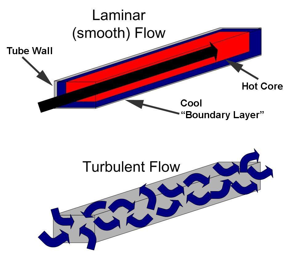
TurbulenceIt is very important that the coolant flowing through the radiator's tubes does so in a turbulent or "rough and tumbling" fashion. This is so that the maximum amount of hot coolant can come into contact with the surface of the tubes so maximum cooling can occur. If the flow is not turbulent, but instead is smooth or "laminar" in nature, a thin boundary layer of fluid will tend to "stick" to the inside walls of the tube, insulating the rest of the fluid from the cooling surfaces of the tube. The result is, the outer boundary layer cools, but the hot inner core never gets cooled. The following diagram illustrates the difference between laminar (bad!) and turbulent (good!) flow.
There are a number of ways a radiator or cooling system designer can achieve turbulent flow. They include:
ThicknessIf you have maximized the surface area and there's absolutely no way to go any bigger, then there may be some advantage to using a thicker rad. Adding thickness to a radiator does not increase its efficiency to the same extent as increasing its surface area does, but as long as there is sufficient airflow it will not decrease the efficiency. Thicker radiators do have slightly more airflow resistance than thinner radiators but the difference is minimal at speed when there is good airflow through the radiator. Where issues can crop up is at idle when the fan(s) alone must supply the needed airflow. Use of a quality, properly shrouded fan or fans is a must to produce the required airflow at idle and slow-speed conditions. Of course, this is true to some extent in all case, but especially so with particularly thick radiators. RowsOne row? Two rows? Three rows? (Or erroneously, single-core? Double core? Triple core?) Which is the best? There is no hard and fast rule here. The number of tubes in each row (from front to back) is only a part of a radiator's overall design. One cannot say that two rows are always better than one. It all depends on the size and profile of the tubes, as well as all the other design features of the radiator - not the least of which is the overall size. The best bet is to choose or spec a radiator using the other criteria for which there are firm guidelines (aluminum, largest area possible, etc.) and then leave the other design elements, such as the number of rows, to a trusted expert such as Griffin. Fin DensityNormally, the greater the density of fins between the tubes, the more surface area there is to be subjected to cooling airflow. However, there is a limit - more is not always better and too much of a good thing becomes a bad thing. Imagine a fin density so high it was almost a solid - obviously that would not be optimal for cooling as no airflow could pass. Another factor involved in the optimal fin density calculation is the operating conditions to which the radiator will be subjected. Dirty, clogged fins are inefficient and even useless, and extremely dense fins are very difficult to keep clean. Not only that, but the fins are fairly delicate and cleaning them can sometimes cause damage that again reduces their efficiency or renders them useless. For these reasons, often the best choice for an off-road rig is a slightly less dense fin count compared to a street or track car - and the overall result will be better real-world, in-service cooling. Griffin understands this and, unlike some others, will not just sell you the product that sounds best on paper (highest fin density). Rather, they will take the time to understand your application and will either design a custom product for you or sell you an off-the-shelf product best suited to your actual needs. Flow - cross and downAlmost all radiators today are "cross-flow". This simply means that the tanks are on the sides of the core, and that the coolant flows horizontally through the tubes from one tank to the other. |
||||||||||||||||
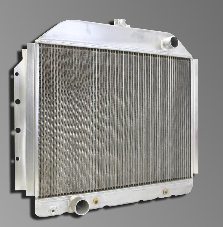
 |
A cross-flow radiator with tanks on the sides of the core. | |||||||||||||||
| Years ago, most radiators were "down-flow" design where one tank was on top of the core and one was below so that the coolant flowed down, vertically, from the top tank to the bottom. This style is still popular today in some circles such as the hot-rod scene. | ||||||||||||||||
 |
A down-flow radiator with tanks above and below the core. | |||||||||||||||
Many, many myths and old wives' tales can be traced back to the old down-flow style radiators and their design and construction. We will deal with them in a separate section. For now, unless you are trying to reproduce a classic hot-rod look or are intent on replicating the factory setup in a rig that originally used a down-flow radiator, know that a cross-flow radiator is the better design because:
Flow - single-, dual-, triple-pass |
||||||||||||||||
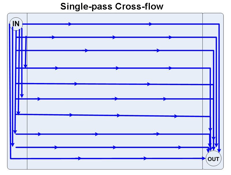 |
The diagram at left depicts the flow in a single-pass cross-flow radiator. The tanks are completely open inside and coolant flows horizontally, in one direction only, from the inlet (high pressure) side to the outlet (low pressure) side. This results in the inlet and outlet being on opposite sides of the radiator. If a rad cap is mounted on a single-pass rad, it is located on the low pressure (outlet) side. |
|||||||||||||||
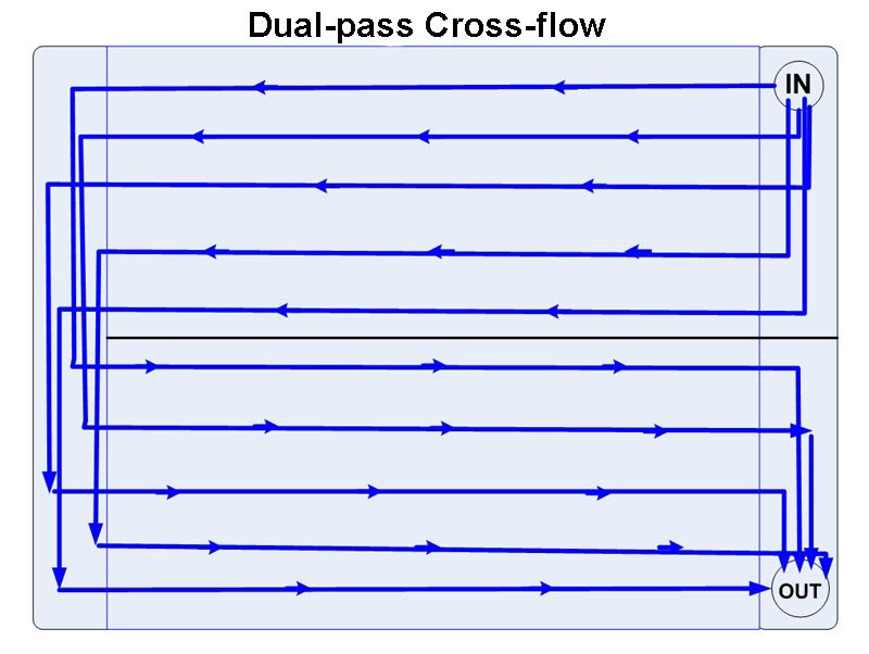 |
Pictured at left is a dual-pass cross-flow radiator. In this configuration, the inlet and outlet are located on the same side of the radiator, and the tank to which they attach is separated in half vertically. This forces the coolant to flow from the inlet to the opposite side tank, then back through the rad to the outlet, as pictured. This essentially doubles the length of the tubes between inlet and outlet, halves the cross-sectional area for flow, and results in:
|
|||||||||||||||
| Let's take a closer look at why all this is so and what it means to our cooling system performance.
Many people mistakenly believe that a dual-pass radiator cools better because the coolant "goes through the rad twice" and therefore "spends longer in the rad and cools more". We know that this is not the case, because "time spent in the rad" is not a defining factor of how well a rad cools, and that flow, turbulence, and delta-T have a far greater effect on cooling efficiency than time. In addition, there are a great many aspects of radiator design, including tube width, tube height, number of tubes, tube construction, and fin count that, in addition to flow pattern, all combine to determine the cooling efficiency of a radiator. So, the question is - does a dual-pass rad cool better or worse than a single cross-flow rad? The answer is "it depends". To understand why this is the case, we need to recall the principles of Pump Performance Curve and Total System Pressure Drop and apply them to the dual-pass rad to see what is happening. We already know that pressure and flow are related, and therefore how increasing the effective length of the cooling tubes with a dual-pass rad increases pressure drop (backpressure). If we examine the pump performance curve, we can also see how the increased head required by the increased backpressure of the dual-pass rad also causes a reduction in flow because the pump always performs somewhere on its curve, and since its head has increased, the flow it produces will be less. The following diagram illustrates the concept, but once again the values are not intended to be representative of any real-world conditions (I just made them up to illustrate the concept).
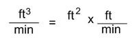
How large an effect on pump flow the increased head required for a dual-pass rad has, depends on the specific pump's performance curve and how large a part of the overall system pressure drop the rad is. Now, to understand the dual-pass rad's effect on coolant velocity, we need to introduce one last equation that relates flow, area, and velocity. Flow in a pipe (or radiator tube) is equal to the cross-sectional area of the pipe multiplied by the velocity of the fluid. If that concept is difficult to grasp, it may help to think of the units involved, as in: Flow (q) = Area (A) x Velocity (V); or cubic feet per minute = square feet x feet per minute
(note: 1 cu ft = 7.48 US gallons) This makes sense - the larger the pipe and/or the faster the fluid is moving - the greater the flow (the more fluid will pass through the pipe in a given time). Now, since q=AxV, this means that if you decrease the area or the velocity, the flow decreases; and by the same token, if flow remains constant and area is reduced, the velocity or speed of the fluid must increase. In a dual-pass rad like the one pictured above, the coolant only has half the number of tubes to flow through at a time - that is, the cross sectional area is halved. And because q=AxV, since the area has halved, for a given flow produced by the pump, the velocity of the coolant doubles. Because velocity increases, so does turbulence. Velocity also has a beneficial effect on the heat-transfer coefficient (how well the radiator sheds the heat in the coolant). Lastly, in a dual-pass radiator, the delta-T (temperature difference) between the coolant and the airflow will be less on the second pass than it is on the first pass - which means heat transfer from the coolant to the air will be less on the second pass than the first. So again, in general, when compared to a single-pass rad, the dual-pass rad has some degree of:
Of course, all this is also a circular process. Area is reduced -> velocity goes up -> pressure drop goes up -> head goes up -> flow goes down -> velocity goes down (remember q=AxV at all times) -> pressure drop goes down -> head goes down -> flow goes up -> and so on (the system quickly reaches a point of balance or equilibrium, it just isn't easy to calculate with a simple equation). There are two final considerations with regards to a dual-pass radiator compared to a single-pass:
How all these factors balance out and therefore the overall effect on cooling system performance of replacing a single-pass rad with a dual-pass rad depends on which, if any, of these factors is the limiting factor on that system's performance. Attempting to calculate and quantify this is a complex problem requiring advanced knowledge of fluid dynamics and thermodynamics and advanced modelling techniques. It is likely well beyond the ability of any enthusiast. The best we can do is understand the general principles at play, and then consult the experts as to whether or not a dual- or even triple-pass rad can or will be beneficial to your cooling system. One cannot definitively say that a dual-pass rad always cools better than a single-pass rad or vice-versa, but there are certainly cases where a dual-pass radiator can be very beneficial if applied to a properly engineered cooling system. The best advice I can offer is: before considering a dual-pass or triple-pass radiator for your vehicle be sure to consult cooling system professionals like those at Griffin Thermal Products. Inlets and OutletsInlets and outlets should be chosen to match the diameter of the water pump inlet and outlet. In the case of the "LS" motors the water pump outlet is 1.25" and the inlet is 1.5". They can be placed on either side of the rad, either together (as in a dual-pass radiator) or on opposite sides (as in a single-pass or triple-pass radiator). For older conventional V8's, Chevy engines normally had the rad inlet on the left and the outlet on the right. In Fords they were reversed with the inlet on the right and the outlet on the left. On the older gen I GM V8's the water pump outlet was usually 1.5" and the inlet 1.75". Filler Neck / Rad Cap LocationAs has been covered, if you are going to use a radiator with a filler neck and mount the rad cap to the radiator, the filler neck should always be placed on the low-pressure tank - i.e. the one that doesn't have the radiator inlet. Additional Ports & PlugsDue consideration should be given to the location and size of steam ports and surge-tank vent ports. Remember they should be located on the low pressure side, just below the rad cap. Most high performance rads do not incorporate a built-in drain plug at the bottom since this can create an unnecessary potential leak point and most racers wouldn't use a drain port for maintenance since the whole system usually comes apart for inspection and replacement as necessary when maintenance is scheduled. Griffin does not normally install a drain in their race radiators since most racers don’t use a drain, and, given the wide variety of chassis a race radiator can be used in, it would be impossible to find a location for the drain that would suit every possible application. AirflowThe best radiator does no good without adequate airflow. Airflow is measured in cubic feet per minute, or CFM. In your design, be sure to allow for adequate airflow at both high and low vehicle speeds. Airflow design for low speeds is fairly easy - you need one or more good quality, powerful fans and a good, complete shroud. Without a shroud you can loose as much as 50% of the CFM you would otherwise have. Ensuring good airflow at higher speeds is more difficult, because high-speed airflow can do weird and wonderful things and you need to account for aerodynamic flow and different air pressure zones. Rather than teach a class on aerodynamics, here are some basic tips:
FansAs previously mentioned, electric fans offer superior flow, mounting flexibility, and computer control compared to mechanical fans. Years ago, it used to be that mechanical fans offered the best performance, but today that isn't so. Mechanical fans are subject to problems with vibration due to air turbulence when run at high RPM. This can lead to premature wear on the water pump. Mechanical fans can also consume up to 20 or more horsepower. Viscous thermo-clutches used to control mechanical fans can be inconsistent and unreliable and offer no computer control. Mechanical fans are limited in the airflow they can provide at idle and slow speeds because they are turning at low RPM. Because the mechanical fan attaches to the engine and not the radiator, clearance must be maintained so that any chassis or engine-mounting flex doesn't cause the fan to eat the radiator (which is bad for cooling!). This makes shrouding a mechanical fan a more difficult and cumbersome affair that consumes valuable under-hood space. |
||||||||||||||||
|
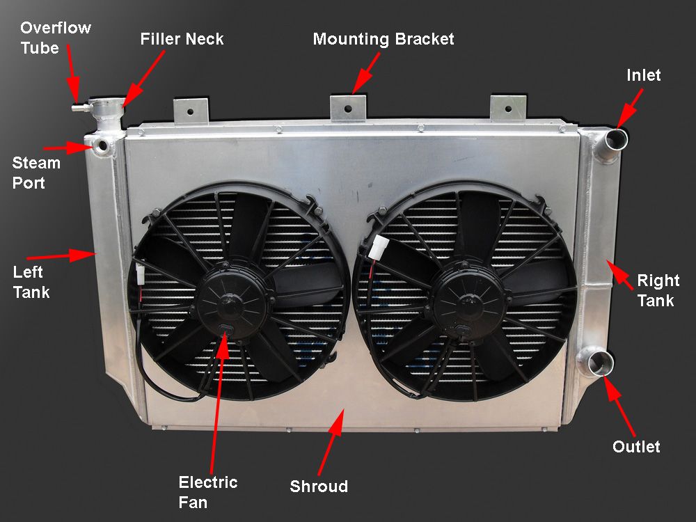
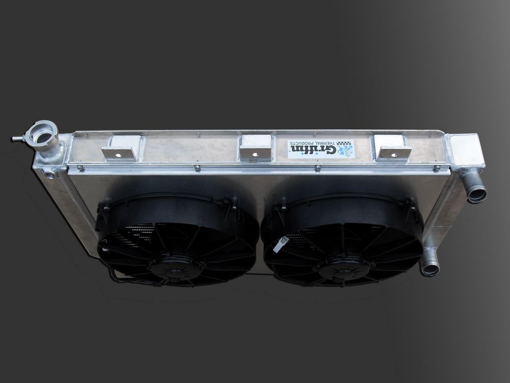
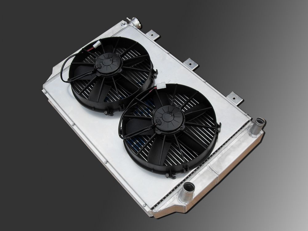
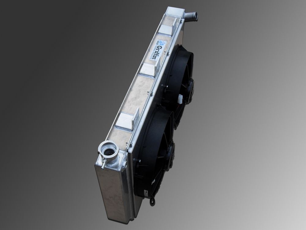
By contrast, electric fans can be very neatly packaged and integrated with the radiator and shroud. Because they aren't coupled to engine speed, electric fans can produce full airflow all the way down to idle. Quality fans like those from SPAL are rugged and reliable with sealed waterproof motors and tough plastic housings. Because they are electrically powered, electric fans can be computer controlled by the engine`s ECM or thermostatically controlled via a thermistor (a temperature sensitive switch installed in the coolant flow). Electric fans are available in a large variety of styles and sizes to fit any size or shape radiator. I like to run two smaller fans in an offroad rig simply for redundancy`s sake - that way, if one quits, you still have one operational. You don't get this choice with a mechanical fan. "Puller" style electric fans that mount behind the radiator and pull air through the radiator, as shown here, are the best choice because they are both more efficient (move more air for given fan RPM) than pusher fans, and they obviously don't block airflow from the front of the rad like a "pusher" style fan does.
|
|||||||||||||||
|
||||||||||||||||

|