 |
Brake Basics By Bill "BillaVista" Ansell |
IntroductionThis article is adapted from a version I wrote in 2008 that was aimed at an audience who build rock-crawling, rock-racing, and off-road buggies, often from complete scratch (custom tube frames). As such, not all will be applicable to our 124 Spiders...however, I am re-publishing it with anything that I think might be useful technical / background information for those seeking to understand braking systems prior to maintaining, troubleshooting, or upgrading them. |
.jpg) |
|||||||||||||||||||||||||||||||||||||||||||||||||||||||||||||||||||||||||||||||||||||||||||||||||||||||||||||||||||||||||||||||||||||||||||||||||||||||||||||||||||||||||||||||||||||||||||||||||||||||||||||||||||||||||||||||||||||||||||||||||||||||||||||||||||||||||||||||||||||||||||||||||||||||||||||||||||||||||||||||||||||||||||||||||||||||||||||||
So, my aim with this article is to help you better understand brake systems and the factors affecting brake performance; to dispel the many common myths and misconceptions, and to address some factors that you don't often find covered by other sources. By the end I hope that you will be able to:
That said, this article isn’t a beginner’s guide to brakes – it is assumed that you are already familiar with the basic components. It’s also not aimed at maintenance – how to replace the brake pads on this or that model car – there are many factory and aftermarket repair manuals that cover the topic well. Also, I won’t be covering aerodynamic braking or down force. Finally, if for no other reason than I detest the damn things, I will not be covering drum brakes, but instead focusing on disc brake systems. Actually, there are a number of good reasons why disc brakes are far superior to drums, including:
Basic Brake ComponentsEach component in a properly functioning brake system must work in harmony with the other components for us to achieve maximum braking performance. We will cover each component; it’s selection, modification, and integration into the ‘system’ as a whole. For now, the basic components of a 4-wheel disc-brake system are:
How Brakes WorkIt seems pretty simple – the driver presses on the pedal and the car stops. But there’s quite a bit going on, and understanding it more fully (yes, including a little physics and math, sorry!) can really help us get the most out of our brake system. Here’s what’s going on: The driver presses on the brake pedal, actuating the piston in the master cylinder (MC). The piston in the master cylinder displaces the hydraulic fluid in the brake lines. Because the system is sealed, the displacement (movement) of the hydraulic fluid moves the piston(s) in the brake callipers. The moving callipers bring the brake pads into contact with the rotor. At this point, because there is no more movement possible in the system, pressure begins to build, and the pads are pressed harder and harder against the rotor, creating friction, and stopping the car.
In summary, in order to stop a car, the brakes must have three properties. They must:
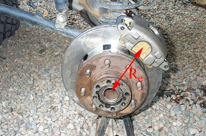
Brake TorqueBrake torque in in-lbs (for each wheel) is the effective rotor radius in inches times clamping force times the coefficient of friction of the pad against the rotor. Brake torque is the force that actually decelerates the wheel and tire. There are two components – how hard the pads clamp the rotor (clamping force) and how far that clamping takes place from the center of the wheel hub. The larger the effective rotor radius, the further the clamping takes place from the wheel center, and the more torque generated by this longer “lever effect”. This is very similar to the manner in which a longer handle on a ratchet generates more torque than a short handle (for the same input). To increase brake torque it is necessary to increase the hydraulic pressure, the calliper piston area, the coefficient of friction between pad & rotor, or the effective rotor diameter. Clamping ForceThe clamping force that a calliper exerts, measured in pounds, is the hydraulic pressure (in psi) multiplied by the total piston area of the calliper (in a fixed calliper) or two times the total piston area (in a floating calliper), in square inches. To increase the clamping force it is necessary to either increase the hydraulic pressure or the calliper piston area. Increasing the coefficient of friction will not increase clamping force. Coefficient of FrictionThe coefficient of friction between pad & rotor is an indication of the amount of friction between the two surfaces. The higher the coefficient, the greater the friction. Typical passenger car pad coefficients are in the neighbourhood of 0.3 to 0.4. Racing pads are in the 0.5 to 0.6 range. “Hard” pads have a lower coefficient but wear less, “soft” pads have a higher coefficient but can wear quickly. With most pads, the coefficient is temperature sensitive - which is why sometimes racers need to “warm up” the brakes before they work well, and also why most brakes will “fade” when they overheat – the coefficient of friction is reduced as the temperature rises. For more info in coefficient of friction, see section on pads. Thermal CapacityThe brake rotors must be capable of absorbing the heat generated by the brakes as they convert the moving car’s kinetic energy into heat. The amount of kinetic energy a car has (and, therefore, the amount of heat the rotors must be able to absorb) depends on the weight of the car and the square of the speed of the car. The rotor’s ability to absorb this heat depends on its mass (weight), and on how well it cools. Exposed as they are to cooling airflow, this is one area where discs are superior to drums.
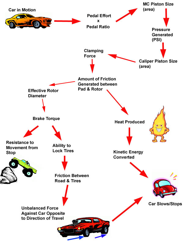
OK, so much for physics and math. Let’s move on now to the more practical side of how the braking system works. Recall that brakes need to be able to do 3 things:
And they must do all three with good and consistent feel! The following “flow-chart” presents a stylized summary of the brake system and its interrelated components / factors. Following it, we will examine each component in more detail:
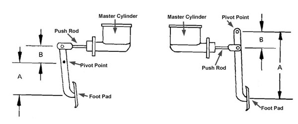
The PedalAs we have discussed, in order to apply the brakes the driver must be able to both move and pressurize the hydraulic fluid. That is, the master cylinder piston has the job of moving the brake fluid through the lines in order to bring the brake pads into contact with the rotor, and of pressurizing that fluid create clamping force. The job of the pedal is to allow the driver to actuate the brakes, and also to multiply the driver’s input through a lever effect called the “pedal ratio.” In other words, the pedal transfers movement & force from the driver’s foot to the master cylinder piston. This is a key concept – that brakes require both movement and force to operate, as the two are largely inversely proportional (that is: as one goes up the other goes down, and vice-versa) – we will return to this concept many times so keep it in mind. The force the driver applies to the pedal when braking is called the “pedal effort”. This amount of force, measured in pounds, is usually insufficient to operate the brakes - values ranging from 50-100 lbs are common. As such, pedals are designed to operate like a lever, multiplying this force before it is applied to the master cylinder piston. The amount by which any particular pedal design does so is called the “pedal ratio.” The pedal ratio is calculated as the distance between the pedal’s pivot point and the centre of the foot pad, divided by the distance between the pivot point and the master cylinder push rod, as shown in the following diagrams.
Pedal Ratio = A / B As can be seen from the diagram – the longer the pedal, the higher the pedal ratio, and the greater the mechanical advantage - meaning the lower the pedal effort required. However, there are trade-offs. First, longer pedals are harder to fit – especially in cramped small-car cockpits. Also, the longer the pedal, the greater the pedal stroke required to move the master cylinder piston – i.e. the further the driver must press the pedal. The best design is a trade-off that will depend on many factors including desired pedal effort, master cylinder and calliper piston diameters, and the room available. As far as pedal effort is concerned, 75 lbs is common for high-performance race-car brakes, 100 lbs feels hard, and 50 lbs is common in power-assisted brakes. Common pedal ratios range from 3 or 4:1 for power brakes up to 6 or 7:1 for manual brakes. Of course, if you are using a stock pedal, you are pretty much stuck with the ratio it has, and must design the rest of the system to accommodate. Just remember – the longer the pedal, the greater the ratio, the less leg force required but the greater the pedal travel required. Longer pedals tend to deflect more under hard use, which can lead to a “spongy” feeling to the brakes. You should always strive to use a pedal that will go from fully retracted to fully applied in as short a distance as possible – usually less than about four inches. Any more than this, and there will not be sufficient travel in the drivers leg to fully apply the brakes under emergency conditions where travel is suddenly increased – such as during brake fade or when there is air in the fluid. Keep in mind that total brake pedal travel includes not only the stroke of the master cylinder piston, but also includes all slop and deflection of all parts in the system. Designing and fabricating a good pedal set up requires engineering far beyond the scope of this article – especially since the brakes are such a critical safety system on the car. My advice is to either incorporate a rugged stock pedal system, or use one of the pre-fab systems available (in a variety of ratios) from many aftermarket vendors. Choose a ratio that will work with the rest of your system and your personal preference for how the brakes will feel. Common ratios are 3:1 for power brakes and 5:1 for manual brakes – but, you may desire a more custom ratio – like 7:1 for manual brakes if using a large diameter master cylinder. One final word on pedal effort: You can design a brake system for any value of pedal effort (values ranging from 50-100 lbs are common), and the pedal effort will largely determine how the brakes “feel” to the driver (excepting problems like brake fade and fluid boil). For this reason, in the following discussion, assume, unless stated otherwise, that we are discussing the brake system with a “consistent and acceptable pedal effort”. For example, if we say, changing to a larger bore master cylinder (all other things remaining the same) will decrease pedal travel but reduce braking power, we mean “with the same pedal effort.” No matter what the system, or mod's we make to it, we always have the option of just increasing pedal effort, but this is rarely experienced by the driver as an acceptable solution. i.e. one “could” design a system with undersize callipers and an oversize MC that could still stop the car effectively if only we would push on the pedal with 300lbs – but clearly this would not be suitable. Brake HydraulicsOK, now we’re getting to the good stuff. Recall that the brake’s hydraulic system must supply movement and force. The movement must be enough to take up all slop, clearance, and deflection of parts as well as move the calliper pistons sufficiently to bring brake pads into firm contact with the rotors. The force must be enough to create enough friction between pad and rotor to stop the car. It is the piston of the master cylinder that provides both the movement and the force, and the brake fluid that transmits both to the callipers. Keep in mind, as you read this section, that the goal is to have a system that provides maximum force with small movement – i.e. we want to be able to brake hard without excessive pedal travel. Force applied to the MC piston creates pressure in the brake fluid. The pressure is the force applied, DIVIDED by the area of the piston. Therefore, the smaller the master cylinder piston, the greater the pressure created.
Recalling that the pressure created is a direct factor in how much clamping force and therefore brake torque is developed, it may seem that for the most powerful brakes, we would want to use a small MC piston. But, the trade-off is the other component required of the brake system – namely movement. Because the fluid is incompressible, any movement in the MC piston translates into movement of the calliper pistons (excluding expansion of hoses and lines, which should be minimal in a properly working system). This movement in a hydraulic system is known as displacement and is calculated as the area of the MC piston multiplied by its stroke. Displacement is a volume, measured in cubic inches. Therefore, the smaller the master cylinder piston, the less displacement created.
Now we can clearly see that there is a trade-off between force and movement in selecting a MC piston size. The smaller the piston, the greater the pressure created but the less displacement produced (and therefore greater pedal travel required.) So far, we have considered only the effect of the size of the MC piston, but of course in a brake system there are two pistons – the MC piston and the calliper piston (for calculations, the total area of all pistons in a multi-piston calliper act the same as a single piston of equivalent area in a single-piston calliper.) There is, of course, a relationship between the pistons in the system that affects both force and movement. Because the brake hydraulic system is a closed, sealed system, and brake fluid cannot be compressed, there is a law of hydraulics that we make use of to multiply force – that is, to apply more force at the callipers than the driver applies to the MC piston. It is quite simple, and quite possibly the most important concept in this entire article. It is this: In a closed hydraulic system, pressure is equal over all surfaces of the containing system. In our discussion of brake systems we will refer to the MC piston as the “input” piston and the calliper piston as the “output” piston. The above law means that whatever pressure is created by the input piston is applied equally to the output piston. Because the output (calliper) piston is of much larger area than the input (MC) piston, this has the effect of multiplying force in the brake system. The amount of force-multiplication thus achieved is known as the brake’s “Hydraulic Ratio” Hydraulic Ratio can be calculated or expressed a number of ways. It is the ratio of fluid displacement by the master cylinder to fluid displaced in the calliper pistons. It is also equal to the ratio of force applied to the MC piston to the force generated by the calliper pistons. Hydraulic ratio is an important factor in the pedal effort equation, the higher the ratio, the less pedal effort is required (and the longer the pedal travel to achieve a given clamping force). The stiffer the calliper and the stiffer the pad, the higher the hydraulic ratio that can be employed. For example, suppose we apply 100 lbs of force to a ½” diameter MC piston, we develop approx. 500 psi. This 500 psi acts evenly on all other surfaces in the system, including the calliper pistons. Suppose the calliper piston has a diameter of 3 inches. Multiplying our 500psi by the area of the calliper piston (~ 7 sq. in), we develop nearly 3500 pounds of clamping force at the brake pads.
Brilliant! From the equation we can see that, for a given input force (pedal effort), in order to increase the force at the calliper (what we’re after) we can either increase the area of the calliper piston(s) or decrease the area of the master cylinder piston (or both). Of course, nothing is ever as easy as that! We can’t forget the other factor – movement. Of course, there is once-again, a trade-off. Unfortunately, both actions that increase force (good!) also increase pedal travel (bad!). That is, if we decrease the size of the MC piston we decrease its displacement - requiring us to increase its stroke to compensate – increasing pedal travel required. Similarly, as we increase the size of the calliper piston, we increase the clamping force, but we also increase the volume of fluid (the displacement) required to move the piston a given distance – the distance it must move to bring the pads into contact with the rotor – this also demands an increase in pedal travel.
So, we can see that, in order to increase the movement of the calliper piston without affecting pedal travel (Mmc), we would have to either increase the size of the MC piston, or decrease the size of the calliper piston – both actions that will decrease force!
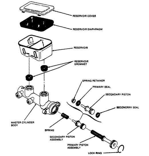
It’s my considered opinion that this interrelationship between force and movements in a 2-piston hydraulic system such as brakes is not very well understood. Consider as evidence the following scenario – a guy swaps rear disc brakes in place of drums on the rear of his car. The resulting brake performance is predictably inadequate – obviously the calliper pistons are much larger than the previous drum-brake wheel-cylinder pistons – meaning that more fluid must be displaced to actuate them. The common advice found is to “swap in a larger master cylinder.” That’s great from a movement perspective – the larger MC piston will displace grater fluid, moving the calliper pistons further for a given amount of pedal travel. BUT – we now know that the result will ALSO be a decrease in force at the calliper pistons (including the front callipers) than was achieved with the smaller MC. So, what are we to do? We really have only two options – either careful compromise – or power assist. The beauty of power assist is that it allows us to substantially increase input force while maintaining pedal effort. This, in turn, enables the production of adequate force at the callipers while allowing the use of larger MC pistons and smaller calliper pistons, decreasing pedal travel. This is particularly important when you consider that most often, a single MC piston must actuate two callipers, (usually one for each of the front or rear wheels). That single MC piston must displace enough fluid to move two or more large-diameter pistons in the callipers. Making it large enough to do so without requiring way too much pedal travel means we compromise the force multiplication in the hydraulic system. The result is, we either accept sub-optimal force (and resulting brake torque), or we must make up for the lack of hydraulic force multiplication by increasing input force. And the only way to significantly increase input force without requiring much greater pedal effort is to increase pedal ratio or add power assist. Given that cockpit space availability place a very real upper limit on how much pedal ratio we can practically achieve – the answer becomes power assist. Master CylindersThe master cylinder is the heart of the brake system. Actuated by the pedal, its piston provides the force and the movement required to apply the brakes. When the pedal is released, an internal return spring returns the piston to its resting position. Initially, as the pedal is pushed, the piston moves forward and fluid volume is displaced, taking up all clearances in the system. This fluid movement actuates the calliper pistons which extend and bring the brake pads into contact with the rotors. Because the fluid is incompressible, once the pads are in contact with the rotor, fluid movement stops and pressure rises. The harder the pedal is pushed, the greater the pressure achieved, the more brake torque is developed. How hard the driver can push the pedal, and therefore how much braking is achieved, is a function of input force (leg strength), combined with pedal ratio and any power assist. The critical specs of a master cylinder are its bore (diameter of the piston) and stroke (how far the piston can travel – and therefore how much fluid it can displace when applied). Common values for bore range from 5/8” to 1-1/2”, and stroke from 1” to 1.5”. Matching both to the requirements of your system is the key to satisfactory performance. Remember that, for a given input (pedal effort) the smaller the bore, the more pressure is generated but the less fluid displaced. Similarly, the longer the stroke the more fluid is displaced, but the greater the pedal travel required. As with most things, the best result is achieved through carefully considered compromise.
Effects of Pedal Ratio and Bore Size on Hydraulic Pressure Output
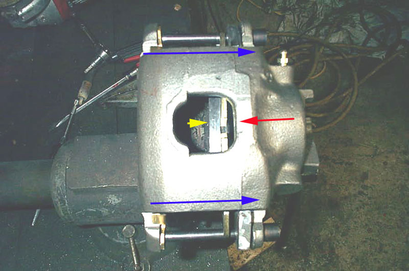
Assuming a pedal ratio of 5:1 - Note that going from a 1" to 7/8" MC bore increases the pressure to the callipers by almost 50% !!! ValvingResidual Pressure ValveA residual pressure valve is a simple, one-way, spring-loaded valve installed either in the master cylinder, or inline between the MC and the callipers/wheel cylinders. They operate by keeping a predetermined amount of pressure in the brake lines, even with the brakes released. The internal spring determines the amount of residual pressure kept in the brake lines – normally 2 PSI or 10 PSI. There are two distinct uses of residual pressure valves: 10 PSI: Drum brakes only. Because drum brakes don’t use callipers and are therefore not self-adjusting there are springs installed to retract the brake shoes away from the drum. A 10 PSI residual pressure valve is used in drum brakes to keep a little pressure in the lines to balance the return-spring force so that the shoes are maintained in close proximity to the drums. Without the residual pressure valve, the return springs would retract the shoes so far from the drums that excessive pedal travel would be required before the brakes are applied. 2 PSI: Disc brakes only. In many race cars and hot rods, the master cylinder is installed at a level below that of the callipers. As such, gravity will draw the fluid from the callipers, causing it to drain back into the MC. The result is a “spongy” feeling pedal and excessive pedal travel. A 2 PSI residual pressure valve is installed in the brake line between MC and calliper to maintain slight pressure in the line and prevent fluid drain back. Note: This valve should only be needed if the MC is lower than the callipers. I have often read where people have advised the use of a residual pressure valve to cure some other problem - spongy pedal or excessive pedal travel (usually caused by insufficient volume from a too-small MC). In cases like this, it may feel as if the RPV has cured the problem, but it is only a band-aid, masking the real problem. Use an RPV only for drum brakes or MC lower than callipers. Do not use an RPV as a band-aid. Find and fix the real problem! When converting from drums to discs, you will need to remove any RPV in the rear circuit. Metering ValveBecause of the return springs present, drum brakes take more movement (pressure and volume) to initially apply than disc brakes whose self-adjusting callipers keep the pads almost or lightly touching the rotors. As such, in disc/drum brakes, a metering valve is used to prevent application of the front disc brakes below a pre-set pressure in the hydraulic system – usually about 75-150 psi – to allow the rear drum brakes to catch up. This allows the front and rear brakes in a disc/drum setup to work more evenly. A metering valve is also known as a “hold-off” valve. When converting from drums to discs, you will need to remove any metering valve in the circuit. Proportioning ValveAs a car brakes, weight is transferred from the rear to the front (ahh – Newton and his Law of Inertia again!). Because braking force should be applied to each wheel in proportion to the weight on it (more weight - more braking force should be applied), there is a requirement to “balance” the braking forces to front and rear wheels. Failure to do so will result in premature lock-up of lightly loaded rear brakes and resulting skid and loss of control. In fact, in hard braking the front brakes perform up to 85% of the braking! In properly balanced brakes, neither the front nor rear breaks will lock up first – braking force is “proportioned” so that they lock up together. Combination ValveA combination valve is found in many OEM vehicles and may combine the functions of the metering valve, the proportioning valve, and a brake pressure warning-light switch. Pressure Limiting ValveUsed on some disc/drum vehicles, a pressure limiting valve performs a similar function to a proportioning valve except that instead of reducing the rate at which pressure to the rear increases, it simply limits the maximum pressure available to the rear. That means, unlike with a proportioning valve, once you achieve that maximum pressure, no matter how hard you press the brake pedal, no more rear braking is possible. Inflexible, non-adjustable, and only marginally useful on very nose-heavy vehicles, they generally suck and should be avoided. Brake Tubing and HosesI’ll keep this section short and sweet. Use rigid hydraulic brake tubing as much as possible, and flexible hose only where necessary (to allow for suspension and steering movement). Even the best flexible hose expands more under pressure than steel hydraulic tubing. Hose expansion gobbles up that limited and valuable pedal stroke. Stock-type rubber flex hoses are OK to use, but Teflon-lined, stainless-steel braided hoses are best. They swell and expand less, giving a firmer pedal. They’re available in custom lengths too. For tubing, use only copper-lined steel hydraulic brake tubing conforming to SAE J524 specs. Use of anything else invites failure. Trust me! Inadequate tubing, especially plastic tubing, is subject to work-hardening, fatigue-cracking, heat damage, excessive corrosion (especially internally, where you can’t see it) and mechanical damage. DO NOT ever use compression fittings or single flares in rigid brake tubing – use only proper fittings and double-flares (be they SAE or ISO – matched to your fittings, of course). AN or JIC fittings of appropriate quality and rating and from a reputable source are suitable for flex hoses and flex hose to rigid tube connections. Most tube today is 3/16” or ¼”. 3/16” is stiffer, lighter, and easier to bend. It and its associated fittings are also the most common. ¼” has less internal friction (less resistant to fluid flow) and is easier to handle without damaging. Note that ¼” DOES NOT “provide more volume” to actuate the callipers more quickly as I have read more times than I care to remember. The MC piston’s bore and stroke determines the fluid volume displaced and therefore the pedal stroke required to apply the brakes. The tubing is sealed and full – its diameter has nothing to do with it (within reason) and you certainly won’t notice the difference between ¼” and 3/16” – except maybe the placebo effect coz your buddy said so! I personally like to use ¼” simply because it’s easier to handle – you can get away with a less-than-perfect bend that you wouldn’t be able to with 3/16” tube. Secure tubing to frame with proper size tube clamps to avoid possible fractures and to prevent fittings from loosening and leaking. Use grommets or some other means to protect brake lines that pass through the frame or body panels. Make sure fittings and connections are in good condition and are properly tightened. Check regularly. 3/16” hardline fittings are 3/8-24 thread, ¼” hardline fittings are 7/16-24 thread. Brake CallipersFixed or FloatingCallipers are either of “fixed” or “floating” design. Fixed callipers are mounted rigidly to the axle and employ one or more pistons on either side of the calliper to press the pads against the rotor. A floating calliper, common on production vehicles, has a piston or pistons only on the inboard side of the calliper. The floating calliper is mounted on pins or slides so that when the piston extends and presses the inboard pad against the rotor, the whole body of the calliper slides on its pins or guides in the opposite direction, bringing the outboard pad into contact with the rotor. Each design has its advantages and drawbacks as follows: Floating callipers are smaller, lighter, and easier to package. They are also cheap, readily available, and easy to mount. Fixed calliper is bigger and heavier than floating calliper. It will also overheat less readily and be more rigid than a floating calliper. Floating callipers cool better as the fluid and piston are only on the inboard side of the rotor. Floating callipers have fewer moving parts and seals to leak or wear out. Fixed callipers tend to apply the pads more evenly, preventing uneven brake pad wear Floating calliper design more easily incorporates a cable-operated parking brake.
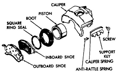
Single or Multi-PistonFixed callipers are, by definition, multi-piston, but floating callipers can also have more than one piston. In addition, fixed callipers may have more than two pistons. Recall that, because pressure is equal on all surfaces inside the brake hydraulic system, the more calliper piston area we have, the more force is exerted for a given input. In other words – we want the most piston surface area possible. One method of achieving this is to use multiple callipers on each rotor – but this approach presents packaging problems inside the wheel. The other alternative is to use either a very large single piston, or multiple pistons. The problem is that using a very large single piston necessitates a huge calliper body – again presenting problems with packaging in the wheel. Thus, multi-piston callipers can be used to achieve greater TOTAL piston area than you could fit with a single piston. That said – a multi-piston calliper is only “more powerful” if the total area of its pistons is greater than the alternative. I.e. – if your buddy is bragging about his bling “multi-piston” callipers, but each has an area of only two square inches, and you have an old truck calliper with a single huge piston of four square inches area, you can comfortable laugh in his face! With floating callipers, effective piston area is the area of the actual piston(s), multiplied by two, because of the sliding action bringing the other side of the calliper into contact. Another advantage of the multi-piston calliper is that it can more evenly press the pads against the rotor, achieving better, more consistent breaking and more even pad wear. Sealing and RetractionCalliper pistons are normally sealed with an O-ring that has a square cross-section. This O-ring stretches when the brakes are applied and the piston extends towards the rotor. When the pedal is released, the O-ring relaxes and retracts the piston. Because the rotor and brake pad surfaces are flat and aligned (or at least should be!) it takes very little movement to obtain pad-to-rotor clearance.
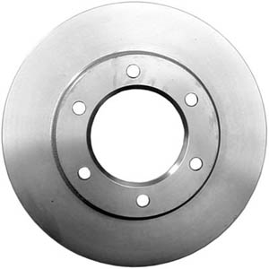
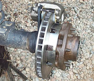
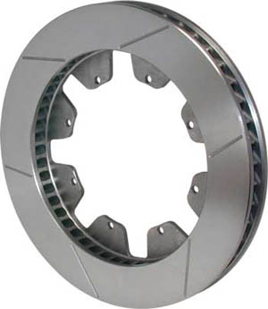
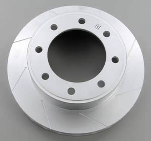
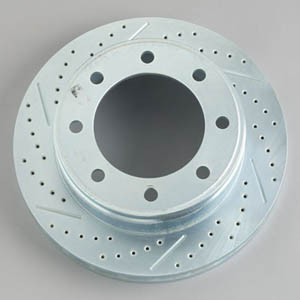
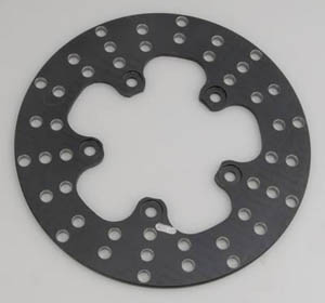
RotorsRotors make me laugh. Actually, the things people do to, and say about, rotors makes me laugh. Rotor size is specified by diameter and thickness (the thickness between the two pad-contact surfaces on either side). Rotors can be solid, vented , cross-drilled, grooved, or some combination thereof. Too many people to count, including many experts, do not understand the true purpose (and consequences) of each of these design factors. Allow me to clarify. Solid – small, solid rotors are adequate for small, light, or slow vehicles. Vented – many medium-to-large rotors are made with radial cooling passages in them to act as an air pump to circulate air from the rotor center to the outside of the rotor. Depending on design, vented rotors may be directional. If the vent passages are curved, they will be more efficient at cooling, but will work in only one direction. If you use curved-vent rotors – make sure you install hem on the correct side of the vehicle! Cross-drilled and slotted rotors – this is the bit that makes me laugh. Way too many people think the drilled holes or machined slots are for cooling. They are not. In very high-performance braking (i.e. race car) hot gas and friction material dust can build up between the pads and rotors as the brakes are used hard, heat and cool rapidly, and the pads wear fast. Rotors can be cross-drilled or slotted to help this dust and gas escape – otherwise it can build up under the pads and reduce friction between pad and rotor, reducing braking. These techniques are really only effective in racing where pads are large and wear quickly and temperatures are very high. Reducing the rotor mass, thereby reducing it’s thermal absorption capacity (remember TR = Kc / 77.8 * Wb ??) Increasing the chance of fatigue and thermal-induced stress cracks in the rotor Reducing the contact area between pad and rotor, thereby reducing braking. In all honesty, cross-drilled rotors on a rock-crawler are pretty funny – unless it’s done purely for weight saving and with the knowledge that it does nothing to enhance braking. Ultimately, slotted rotors work well, and judiciously drilled rotors do too – but if you see a Swiss-cheese rotor it most likely means the designer/builder doesn’t actually understand how brakes work.
PadsIt all comes to a head at the brake pads. Pads need to be clean, even, and have a high coefficient of friction against the rotor for maximum braking performance. Disc brake pads are available in a dizzying array of compounds - all claiming certain benefits. One thing that is consistent is that the pad's compound will have a different coefficient of friction depending on whether it is cold or hot. Race car folks are familiar with this as it is often heard that the brakes must be "warmed up" before they work well. As a general rule of thumb, the following compounds exhibit the following coefficients of friction: Organic – cold 0.44, hot 0.48 semi-metallic – cold 0.38, hot 0.40 Metallic – cold 0.25, hot 0.35 Synthetic – cold 0.38, hot 0.45 The higher the coefficient of friction, the "softer" the pad is said to be. Keep in mind that there are other factors to consider when selecting pads, such as noise and wear. The softer the pad is, the more rapidly it will wear. All DOT legal brake pads (OEM and road-car aftermarket) are mandated by law to be marked with a two-letter code, called the "DOT Edge Code" that represents the coefficient of friction when a 1" square piece of friction material is subjected to varying conditions of load, temperature, pressure and rubbing speed on a test apparatus known as the Chase machine. The first letter of the code, sometimes known as the "cold" code, represents the normal friction coefficient. This is defined as the average of four test data points measured at 200, 250, 300 and 400 degrees Fahrenheit. The second letter of the code, sometimes known as the "hot" code, represents the hot friction coefficient based on a fade and recovery test. Recovery is basically the period where the brakes are gradually cooling off. The hot friction coefficient is defined as the average of multiple data points: 450, 500, 550, 600 and 650°F on the first recovery cycle of the pad; and 500, 400, and 300°F on the second recovery cycle. The range of friction coefficients assigned to each code letter are as follows: C = less than 0.15. D= 0.15 to 0.25. E= 0.25 to 0.35. F= 0.35 to 0.45. G= 0.45 to 0.55, and H= over 0.55. Each letter grade spans a range of coefficients, but the combination of the two letters and the order in which they come can be a useful indicator of pad performance as it demonstrates the change in coefficient of friction for that pad from cold to hot (and vice versa). For example, an FE pad will grab better when cold (i.e. tends to fade when hot) whereas an EF pad would not grab well when cold (i.e. would need to be warmed up for max performance). Note that the coefficient of friction of steel on steel is 0.25, so EE pads grab only marginally better than no pads at all! FF pads are usually considered the minimum for a high-performance brake pad. Some example Edge Code's are:
Any good aftermarket racing pad should be sold with a precise coefficient of friction identified for both cold and warm performance, or even a curve showing coefficient of friction vs. temperature. Whichever pad you use, the type of lining, edge code, or exact spec can be useful in determining the coefficient of friction to use when making brake system calculations. Bedding-in Brake PadsWhen new brake pads are installed, they should be "bedded-in". Bedding-in brake pads is a process of breaking them in before severe use, similar to the way an engine or set of gears must be broken in. To perform the “break-in”, follow the steps listed below: Step 1: Make 10 stops from 30 mph (50 kph) down to about 10 mph (15 kph) using moderate braking pressure and allowing approximately 30 seconds between stops for cooling. Do not drag your pads during these stops. After the 10th stop, allow 15 minutes for your braking system to cool down. Step 2: Make 5 consecutive stops from 50 mph (80 kph) down to 10 mph (15 kph). After the 5th stop, allow your braking system to cool for approximately 30 minutes. This completes the “break-in” of the pads to the rotor surface. Full seating of new brake pads normally occurs within 1000 miles. Brake Performance and LimitsThere should be only one limit to how well your brakes work – traction. The traction between tire and road should always be the limiting factor to how quickly you can stop. Exceeding the traction limit causes the tires to lock-up and skid. If you can do this under all conditions, with reasonable and comfortable pedal effort, then your brakes are adequate. If not, some other factor is limiting their performance, and maintenance or modification will be required. The other, undesirable, limiting factors are: Force LimitAt force limit, you push as hard as possible on the brakes but can’t stop any quicker. If you could push harder, the vehicle would stop quicker. Force limit can be altered by reducing master cylinder size, using different brake pads, adding or upgrading power assist, increasing pedal ratio, increasing calliper piston area, or increasing effective rotor diameter. Deflection LimitAt the deflection limit, the pedal hits the floor or the MC piston hits its internal stop before max brake force is generated. I.e. – the combination of designed clearance and unwanted deflection in the system exceeds the available travel. Clearance is determined by the volume of fluid required to be displaced to bring the pads into contact with the rotor, and is chiefly determined by the size of the calliper piston(s). Unwanted deflection can come from pedal and pedal-mount flex, MC mount flex, calliper bracket flex, calliper flex, hose expansion, trapped air, unevenly worn pads or rotors, and other worn components such as wheel bearings. Assuming all air is bled from the system and all components are in good working order, deflection limit can be altered by increasing MC piston diameter, decreasing calliper piston diameter, upgrading flex hoses, reducing the length of flex hose used, or using stiffer callipers, brackets, and pedals. Wear LimitThe brakes effectiveness can be limited by worn components. If pads or rotors are worn excessively, or if any seal, tube, hose, bracket, or fitting is damaged, worn, or leaking, a reduction in performance, or worse, brake failure, can result. The likelihood of reaching the wear limit can be reduced by using different (higher quality) pads and/or rotors, using larger callipers and rotors, or increasing brake cooling. Good inspection and maintenance practices can prevent reaching the wear limit. Temperature LimitWhen brakes overheat, you reach one of the other limits (force, deflection, or wear) much more quickly. That is, hot brakes can cause lack of braking force (commonly called brake fade), increased deflection (excessive pedal travel), or rapid component wear – ranging from pad/rotor wear to boiling fluid and cooking seals. The keys to avoiding a temperature limit are: Using sufficiently large/heavy brakes. Sufficient brake cooling. Selection of components designed for the temperatures encountered – including pads, rotors, callipers, and fluid. Brake Fade and other complaints - Design TroubleshootingThe previous section covered the technical aspects of brake limits – but even I wouldn’t expect you to chat with a supplier or fellow driver and say “Yea, the brakes aren’t great - I think I have a deflection limit with occasional intermittent force limit.” Well, actually, I might say that – but then Charley would mock me for hours – much to everyone else’s amusement. To avoid this situation, let’s examine the most common brake performance complaints in every-day language. (I was going to say “every-day parlance” but that would have been too ironic, I think!) This section is focused on problems that occur after system modifications or design. That is, it helps you diagnose problems in your brake system design. If your brakes worked satisfactorily at one point, but no longer do, see the following section titled “Maintenance Troubleshooting”. In the following tables, I have included a column entitled “compromises” because, as we know, changing one aspect of a system often affects the others. For the sake of brevity I have included only the compromises affecting the operation of the brakes – it may be assumed that added complexity, cost, and decreased availability of parts are always possible outcomes. For example, if the solution to a particular problem is to install a stiffer calliper this will likely be more expensive, complicated and time-consuming - if such a part is even available – however there are no drawbacks or compromises in the operation of the brake system itself to using stiffer callipers – in this case, the “compromises” column will be blank. Brake Fade“Brake fade” generally refers to any loss of braking caused by overheating. In fact, there are three very distinct forms of “brake fade”, and it is useful to distinguish between them, as their symptoms and solutions are entirely different. Pad Fade.Pad Fade is caused by the temperature of the brakes exceeding the maximum temperature limit of the brake pad friction material. When the maximum temperature limit is reached (and even before, as it is approached), brake pads can expel gases when heated, gasses that act as a lubricant between pad and rotor. When pad fade occurs, the pedal will feel “normal” (high and firm) but there will be very little stopping power. Pumping the brakes will not help. Solutions to pad fade are:
Fluid BoilWhen the temperature of the calliper exceeds the boiling point of the brake fluid, tiny bubbles are formed in the brake fluid. As a result, the pedal goes soft and perhaps even to the floor as the fluid is no longer incompressible. Once this has happened, the fluid must be replaced. Over time brake fluid can absorb water vapour, and the more water vapour in the fluid, the greater its susceptibility to fluid boil. Solutions to fluid boil include: flush and fill with new brake fluid, use a brake fluid with a higher boiling point, improve cooling of the calliper, or use a calliper with an insulated piston. Green FadeGreen fade occurs only with new brake pads if they are not “bedded-in” properly after having been installed. Bedding-in brake pads is a process of breaking them in before severe use, similar to the way an engine or set of gears must be broken in. Green fade is caused by gas or liquid boiling off the organic pad lining on initial heating. The gas or liquid not only acts as a lubricant between pad and rotor, but can also “glaze” the surface of the pads by cooling and re-solidifying into a hard slick surface with a very low coefficient of friction. The solution to green fade is to bed in brake pads. To do so, follow the steps outlined in "Bedding-in". Hard Pedal“Hard Pedal” is the term used to describe brakes that require excessive pedal effort – i.e. the driver must push too hard on the pedal for the brakes to work. This condition “feels” to the driver like the brake pedal is very “hard”. Complaint: Pedal feels hard
Low Pedal“Low Pedal” is the term used to refer to a brake pedal that requires an excessively long stroke to fully apply the brakes. What we are experiencing with low pedal is a deflection limit. In some cases, the brakes work only after being “pumped” a few times. What’s happening here is that the driver is able to displace more fluid more quickly than the callipers retract, and is therefore able to provide the volume required by pumping the brakes. This is usually a symptom of incorrect valving, such as lack of required residual pressure valve. Complaint: Pedal travels too far / only works when pumped
Spongy PedalOften present with, but not to be confused with, low pedal; a spongy pedal starts high and doesn’t travel too far – but it doesn’t feel firm and solid. Instead, the brakes feel soft, squishy, and spongy when applied. Complaint: Pedal feels spongy
Overly SensitiveBrakes that develop enormous clamping force (usually by generating high pressure) with very little pedal effort will feel overly sensitive to the driver. They are hard to modulate, particularly for med- to high-speed work, and are generally unpleasant to drive. Exactly the point at which this occurs will be a matter of driver preference combined with the vehicle’s use. Personally, I like brakes on the more sensitive side as it allows tip-toe control in serious vertical and off-camber situations – which can be very useful, particularly when the drive is also occupied with managing selectable lockers, three transfer case levers, a clutch, and cutting brakes. Complaint: Pedal feels overly sensitive / brakes lock-up too easily
Brake System DesignThe following are some general guidelines for designing a brake system from scratch. Although they are presented in a particular order, some juggling may be required. That is, you may come to a certain point (say, pedal-ratio determination) find out that you are limited by some other factor (room available for pedal) and have to juggle both prior and remaining decisions (calliper piston size, master-cylinder size, power booster selection) to work around the limitation. Following the discussion I have included an Excel spreadsheet (.xls) that will aid in the calculations and can be used to more easily see the affects of playing with the different variables. Step 1: Decide on disc brakes or drums. The answer is discs. Go on to step 2. Step 2: Choose and check rotor. While the rotor you use is often determined by the axle you have chosen, if you have a choice: Choose the largest diameter rotor that will fit in the wheel (to make room for the calliper, this is usually about 3 in. smaller than the wheel diameter – i.e. 12” for a 15” wheel) If possible, always choose a vented rotor If you plan to use the brakes hard, a lot, (as in racing) consider directional-vented rotors as well as slotted and/or cross-drilled rotors. Don’t overdo the cross-drilling for the sake of appearances! Step 3: Check thermal capacity of chosen rotor Using the equations in this article, check that each rotor is at least massive enough to be able to absorb the kinetic energy from a single stop from maximum speed at maximum weight without exceeding 1000°F If you plan to use the brakes hard, a lot, (as in racing) re-do the above calculation assuming the rotor’s initial temperature is 500°F rather than ambient temperature. Step 4: Choose calliper Normally, the choice of rotor will dictate the calliper used – either from the same make/model of vehicle or as a matched set from a high-performance company. However, if choice is available: Select the stiffest calliper available, with the highest maximum pressure rating. Select a calliper with the largest total piston area possible. If wheel & suspension clearance and mounting brackets allow – consider using a fixed calliper – most high-performance callipers are of fixed design. Consider use of multi-piston callipers – depending on availability and total piston area (you may find that one large piston affords more are than two small, depending on design) Step 5: Determine brake torque required using equations given in this article TBr = Friction Force on Tire x Rolling Radius of Tire Step 6: Calculate required hydraulic system pressure: Once the rotor and calliper are chosen, you have all the information required to calculate the hydraulic pressure required to operate the brakes at maximum capacity – that is, the pressure required to achieve maximum brake torque, as calculated above in step 5. The equation is: PM = TBr / (µL x AT x RE ) Where PM = Maximum hydraulic pressure (psi) TBr = Brake Torque Required (ft-lbs) AT = Total effective area of calliper’s pistons (sq. in.) RE = Effective rotor radius (in.) – measured from the center of the rotor to the canter of the brake pad. The answer will probably vary from several hundred to perhaps as much as fifteen hundred PSI. At this point, check that the components you are using, especially the callipers, are rated for this pressure. If you cannot find a calliper rated for this pressure, you have three choices: Use a calliper with more total effective piston area (larger and/or more pistons) Use a larger diameter rotor (to increase rotor effective diameter) – hey – didn’t I already tell you to use the largest diameter rotor possible! Use more than one calliper per wheel. Two identical callipers on the same rotor will halve the pressure, but double the displacement, required to achieve max brake torque. Step 7: Decide on desired pedal effort Pedal effort desired to stop the vehicle at maximum deceleration is a personal choice. In a race-car it may be as much as 100 lbs – which feels like a pretty hard push. In road cars it is normally less. If you are not sure, 75 lbs is a good starting point. Step 8: Decide on power or manual brakes. Unless space or weight is at an extreme premium, I would always recommend power brakes – especially in a big or heavy car, or one with large tires. Without power brakes, you are faced with a direct trade-off of pressure (brake power) vs. displacement (pedal travel). The beauty of power brakes is that they allow you to use a pedal and MC combination that is large enough to have a nice, short travel but still develop the required pressure without excessive pedal effort because of the power assist. Except for a little extra space required and minor expense, it adds to your brake system performance without any drawback or compromise. Step 9: Determine desired pedal ratio, master cylinder size (piston area), and power assist to achieve max braking with desired pedal effort. The three factors of pedal ratio, master cylinder size, and any power assist must be calculated and juggled together as they all affect one-another. Where one factor is fixed or beyond your control (e.g. using a stock pedal assembly), adjustments or compromise in the other factors will be necessary. Pedal ratio: Pedal ratios range from 3:1 to 7:1. When selecting a pedal ratio, consider the mounting space required, not only for the length of pedal, but also for the stroke required at the footpad (will the pedal hit the floor before the full master cylinder stroke is used?). Remember too, that the greater the pedal ratio, the longer the pedal, and the more susceptible it will be to flex or twist, introducing unwanted deflection. Even without flexing, a longer pedal can “feel” spongy to the driver. Also, the longer the pedal, the more pedal travel the driver will feel as the foot pad swings through a larger arc. If in doubt, start with 4:1 for power brakes and 6:1 for manual brakes. Calculate MC pushrod force Multiply your desired pedal effort by the pedal ratio to obtain the manual force on the MC pushrod. If pedal ratio is 5:1 and pedal effort is 75 lbs, the force on the pushrod is 5 x 75 = 375 lbs. Select required MC size With the pushrod force known, we can now calculate the MC piston size required to achieve the desired hydraulic pressure previously calculated. In order to do so, divide the pushrod force by the pressure to get the area of the MC piston, and then convert that area to a diameter using the formula for the area of a circle (A = pi(d/2)^2) or the accompanying chart. If the exact area you need is not available, you will have to use the next closest available size, and recalculate the actual pressure achieved. Remember that, as the MC area (diameter) gets smaller, pressure (and force) go up, but so does travel required. Table of Master Cylinder Sizes and their Piston Areas
e.g. If we require 1000psi hydraulic pressure, and have decided on a pedal effort of 75lbs and a pedal ratio of 5:1: A = F / P Where A = Area of master cylinder piston required So MC area = 375lbs / 1000psi = 0.375 Square Inches. Referring to the table, we find that aren’t likely any master cylinders available with this exact area. The closest is an 11/16” diameter MC piston, which gives an area of 0.3712 sq. in. If you find that the MC size you want is not available, or isn’t available in a configuration you desire, you will have to use the closest size available and recalculate. In this example, let’s assume we can’t find an 11/16” MC we want to use, so we settle on ¾” – which ha an area of 0.4418 Sq. in.. Check the hydraulic pressure generated with this MC using the equation: P = F / A P = 375 lbs / 0.4418 sq. in. Immediately we can see that using a ¾” MC will not allow us to generate sufficient hydraulic pressure to maximally apply the brakes. At this point, we have a decision to make – We can: Use a pedal with a higher pedal ratio Accept an undesirably high pedal effort Reduce the pressure required by going all the way back to calliper / rotor choice and either Increasing the diameter of the rotor, and/or Increasing the size/ number of calliper pistons. Option (1) may be a viable alternative, but what if we have limited space or are already set on a particular pedal assembly and don’t want to fabricate or buy a custom pedal? Option (2) is really out of the question, as it defeats the purpose of the whole exercise. Finally, option (3) is not only unlikely to yield the magnitude of change required, but it’s very likely that we’re already using the maximum size rotor and calliper. So what are we to do? The solution here is power brakes. By adding power brakes, we can dramatically increase the MC pushrod force without having to alter any of the other variables. Not only will this let us choose a MC in a more commonly available size, but will also allow us to use a larger MC so as to keep pedal travel down. Calculating the exact factor by which a power brake booster will multiply pushrod force is difficult to do as modern vacuum and hydraulic boosters are both fairly complicated in design and often not sold with an exact boost specification. Boost factors will depend on the size and design of the booster and will range from about 2 to 5 or more. This makes exact calculations with power brakes more complicated, but experience has shown that, with power brakes, one should normally use a pedal ratio of about 4:1 and a master cylinder with at least a 1” diameter. Step 10: Check displacement of fluid with chosen components, verify that pedal travel will be acceptable, and juggle / recalculate as required. The final thing to consider, now that we have chosen a master cylinder, is the effect the MC bore size will have on pedal travel. Unfortunately, precise calculations are complicated, as it is difficult to know the amount of travel consumed by all the deflections (both design and unwanted) in the system. We can calculate the displacement of the MC by multiplying the area of the piston by its stroke to arrive at a value in cubic inches. (Good aftermarket master cylinders should always specify the stroke, but with stock replacement or OEM parts it may not be as easy to come by. One foolproof method is to measure the stroke with the master cylinder out of the vehicle – values from 1 to 1-3/4 inches are common.) In theory, we could then compare this to the volume required by the calliper pistons. The volume required by the callipers would be calculated as the area of the piston multiplied by the travel required to bring the pads into contact with the rotor. This last variable is difficult to measure or calculate. Not only that, but the result would only be valid for maximum stroke of the pedal (and therefore master cylinder piston) and we surely want the brakes to apply well before the end of the pedal stroke. Ultimately, we may have to rely on experience and/or testing to achieve the right balance between braking power/pedal effort, and pedal travel. Again, power brake boosters are an enormous asset here, as we can select a large bore MC that will displace a large volume of fluid (and therefore minimize pedal travel), and still produce sufficient pressure. As a rule of thumb, 4-wheel disc brakes require a master cylinder of at least 1” bore, and frequently 1-1/8” or more. Step 11: With all components selected, calculate actual maximum brake torque developed and compare with calculation of brake torque required.
Maintenance TroubleshootingThis section provides troubleshooting advice for a brake system that at one time functioned acceptably, but no longer does. That is, it is focused on maintenance problems. If you are experiencing problems with a newly designed/modified/installed system – refer to the previous section titled “Brake Fade and other complaints.”
|
||||||||||||||||||||||||||||||||||||||||||||||||||||||||||||||||||||||||||||||||||||||||||||||||||||||||||||||||||||||||||||||||||||||||||||||||||||||||||||||||||||||||||||||||||||||||||||||||||||||||||||||||||||||||||||||||||||||||||||||||||||||||||||||||||||||||||||||||||||||||||||||||||||||||||||||||||||||||||||||||||||||||||||||||||||||||||||||||
|
|