|
Grizzly Accessory Fuse Panel By Bill "BillaVista" Ansell |
IntroductionOne of the most fun parts of ATV ownership is modifying it to your own personal needs and tastes - taking something stock and making it your own. Many of the most useful and popular accessories are electronic. I myself have big plans - heated grips, heated seat, winch, GPS, extra lights, stereo - the list is long. However, many ATVs, including the Grizzly, don't come from the factory optimized for adding aftermarket electronics. And cobbling them on one at a time can lead to a spaghetti mess of spliced and tapped wires that can be a mess at best and at worst lead to poor performance of your electronics or even unsafe wiring. |
 |
That's why one of my first mods was to add a small auxiliary fuse panel, powered through a 40 amp relay that is activated by the main ignition switch. Now I have a tidy little system that tucks neatly under the hood amongst the stock wiring. It has six available accessory slots, each individually fused, uses standard automotive ATC-type fuses, and the whole thing powers up or down with the key (main switch) so that there's no fear of accidentally draining the battery by unintentionally leaving accessories on. Here's how I did it. Overview |
|
 |
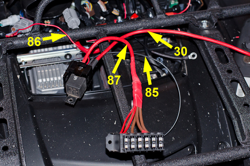
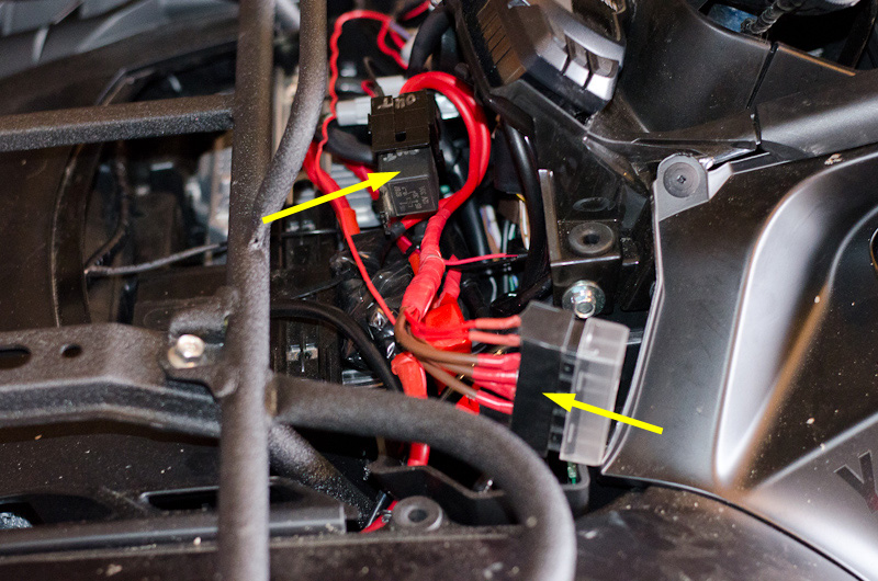
This is a shot of the finished product. The left yellow arrow indicates the relay and the right is pointing to the aux fuse panel. |
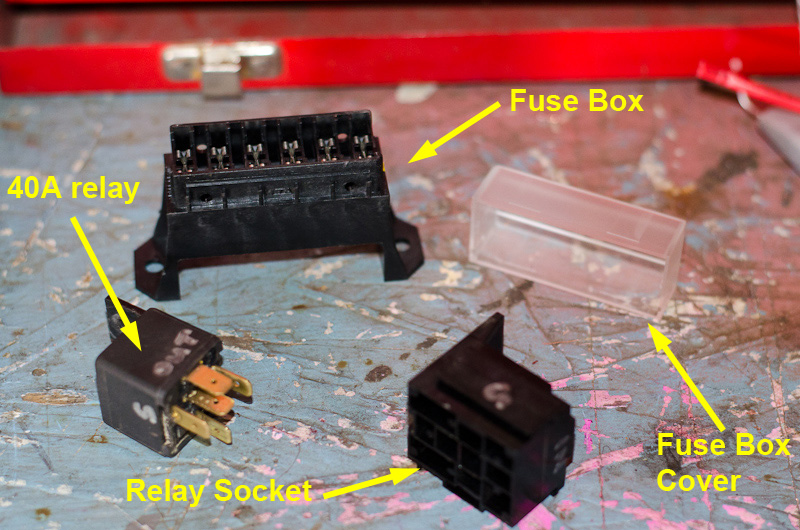 |
These are the main parts that will be installed. |
Fuse Panel |
|
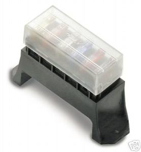 |
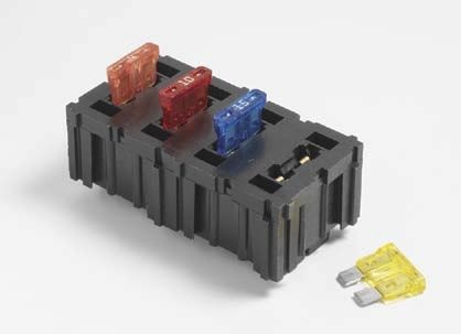
This is a shot of the fuse panel that I used, with fuses and the cover installed. It has standard male blade terminals underneath to which you connect the power wire in to the fuse and the power wire after the fuse, for each of this six circuits / fuse slots. |
 |
These are the ATC-style automotive blade-type fuses that it uses. |
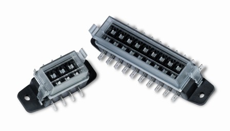 |
There are may other small fuse panels that you could use, including this one that has the blade terminals on the side rather than underneath. The main criteria is that it fit into the very limited space available. Personally I don;t particularly like this style because the terminals on the sides are pretty exposed. |
 |
This is yet another style that is available in a small package. |
RelayA relay is a remote-controlled electrical switch. It allows a low current control circuit to control (turn on and off) a second high current circuit. Using a relay can therefore allow you to isolate the the high power (current) demand of some accessories from the switch that is used to turn the accessory on or off. This means the the actual switch that controls the accessory needs only to carry a fraction of the current that the accessory itself requires. As such, smaller, more ergonomic, and cheaper switches can be used to control even the highest power accessories. If it weren't for relays, high power accessories would have to be controlled by very large, heavy, and expensive switches capable of handling 40, 50, or even 100 amps. Other advantages to using a relay include:
How it worksInside a relay is a small electromagnetic coil. When a small control current is passed through the coil a magnetic field is created. This magnetic field pulls a set of contacts together and thus the high current now flows through these closed contacts and to the device being powered. When the control current is removed the magnetic field collapses and a small spring applies force and holds the main contacts open until the control switch is switched on again and control current once again flows through the coil. A relay can be controlled with an electrical current as small as 150 milliamps (at 12 volts DC). Depending on the rating of the relay, the device being powered through the relay (the switched output of the relay) can be as high as 30, 40, or even 75 amps. |
|
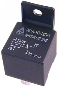 |
This is a typical automotive style relay. This one with a built-in mounting tab. The circuit schematic is printed on the top, which we shall look at momentarily. Not also that the specification (current carrying capacity) is also printed on it. This is where it says: NO: 40A / NC: 30A 12VDC This means that its capacity is 40 amps through the "normally open (NO)" circuit, and 30 amps through the "normally closed (NC)" circuit, both ratings at 12 volts direct current (12VDC) - which is the voltage your car and ATV work on. We;; look at what the "normally open (NO)" circuit and the "normally closed (NC)" circuit are shortly. |
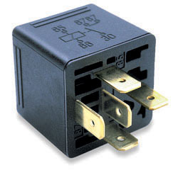 |
Another view of the typical 40A automotive relay, showing the terminals to which the wiring is attached. Note that this one also has the circuit diagram stamped on it - this time on the side. This style of relay is also commonly known as a "Bosch Relay", so named after the company that popularized its use. If you look carefully at the bottom, beside the blade terminals, you will see small numbers stamped next to each terminal. This is then umber of the terminal, and each number corresponds to a number on the circuit diagram. |
Note that both of these relays have five terminals, and therefore also five numbers in the schematic. This type of relay is known as a single-pole double-throw (SPDT) relay - it has both a normally-open contact and a normally-closed contact in the main high-current circuit. Let's just explain that terminology as it is quite useful to understand. Switch TerminologyFor all switches, whether they are simple mechanical switches (like a light switch in your house) or an electromechanical switch like a relay, the number of 'poles' indicates how many electrical circuits are controlled by the switch. The number of 'throws' indicates the number of positions of the switch that result in an electrical connection. Note that this means that, depending on the switch design, the number of throws can be either:
The following simple switch diagrams should help clarify this: |
|
 |
This is the schematic diagram for a single pole, single throw (SPST) switch, This is the simplest kind of switch. An example would be a simple on-off switch. It controls a single circuit (so "single pole") and there is only one switch position that results in a circuit connection - the "on" position (so "single throw"). Of course, this switch has two control positions: "on" and "off", so the number of throws is one less than the number of control positions In the diagram at left, the switch is seen in the "off" or "open" position - i.e. there is no circuit completed. |
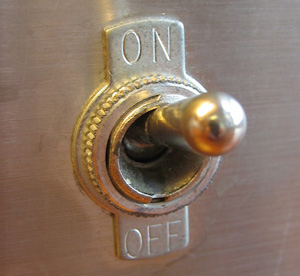 |
This is an example of an actual SPST switch. It is single pole - so It controls a single circuit (turns something ON or OFF) It has a single throw - so there is only one switch position (ON) that results in a completed electrical circuit. It has two control positions - ON and OFF |
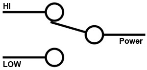 |
This is the schematic diagram for a single pole, double throw (SPDT) switch, This is also a simple and very common kind of switch. An example would be a selector switch where the user selects between two positions - a light switch with "HI" or "LOW" positions is an example. It controls a single circuit (so "single pole") and there are two switch position that can results in a circuit connection - the "HI" position or the "LOW" position - so "double throw"). This switch could have two or three control positions: It could be just "HI" and "LOW" and therefore always be in one or the other, or it could also have an intermediate "off" position, so depending on the actual switch design the number of throws could be either be the same as the number of control positions (in the case of "HI" or "LOW") or one less than the number of control positions (in the case of "HI" "OFF" "LOW") In the diagram at left, the switch is seen in the "HI" position. |
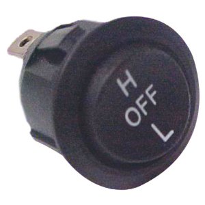 |
This is an example of an actual SPDT switch. It is single pole - so it controls a single circuit (turns something to HI, OFF, or LOW) It is double throw - there are two positions (H and L) that result in a completed electrical circuit. It has three control positions - H, OFF, and L |
Back to Relays |
|
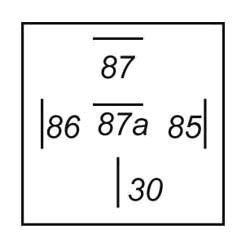 |
This is a schematic diagram of the five blade terminals on an SPDT relay. They are always in this orientation and always the same, regardless of the brand or rating - making them interchangeable. The terminals are as follows:
|
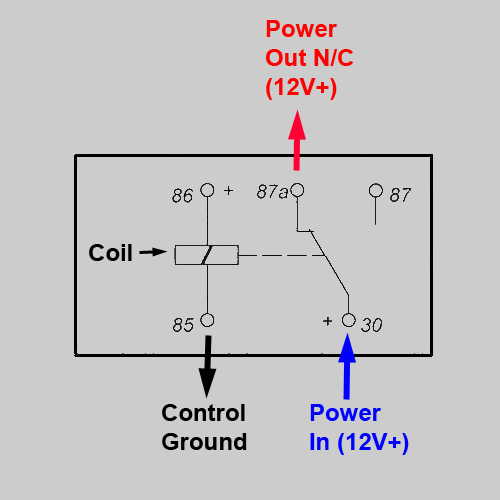 |
This is a schematic of an SPDT relay. The electromagnetic coil is illustrated in the middle. When there is no voltage across terminals 85 and 86, no current flows through the coil, therefore no magnetic field is produced, and the relay's movable contact (connected to terminal 30) is held, by spring tension, against the electrical contact which is connected to terminal 87a (the normally closed contact). In other words, when no voltage is applied to the relay coil, terminal 30 is connected to terminal 87a, and therefore high current 12V DC is available at terminal 87a, as shown in this schematic
|
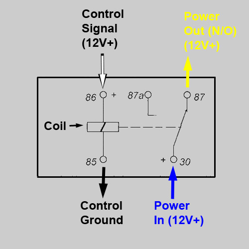 |
When 12 volts is applied to the relay coil (terminals 85 and 86), current flows through the coil, a magnetic field is created and thus the movable contact (connected to terminal 30) is pulled by the magnetic field into contact with the electrical contact which is connected to terminal 87. In other words, when voltage is applied to the relay coil, terminal 30 is connected to terminal 87, and therefore high current 12V DC is available at terminal 87, as shown in this schematic. |
So, in practical terms, what we do is wire terminal 86 to some source of switched 12V DC - that is, power that comes from either a small dash switch or even from the main key switch. Let's assume the key switch for this example. We connect terminal 85 to ground. We connect terminal 30 to a fused source of high current - say a nice fat 8 or 10 gauge wire from the battery or main distribution block. Now, when the key is off, terminal 87a will have high current 12V DC, and when we turn the key on, the relay switches, and high current 12V DC is available at terminal 87. So we can wire terminal 87 to a single high-current accessory, or in my case, to a small fuse panel, and now when we turn the key on our fuse panel is powered, and when we turn the key off power is removed from the fuse panel and any accessory wired to the fuse panel. It's not terribly common to wire anything to terminal 87a - the "normally closed" terminal, as anything so wired would be "on" when the key is off, and "off" when the key is on. Perhaps one example would be a small alarm warning light that you want to come on only when the key is off. But like I said, normally-closed connections are rare. So much so, in fact, that you can get relays without them. That is, instead of a SPDT relay, you can get an SPST relay! |
|
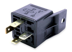 |
This is a 4-terminal SPST relay. It's the same as the SDT, except that there is no terminal 87a, so no contact where 12V DC is available when the relay is not energized (i.e. when the relay isn't getting current to terminal 86) Note the schematic is still stamped on the side, and that the terminal pin-out is exactly the same as the SPDT relay already shown except terminal 87a (the centre one) is missing . |
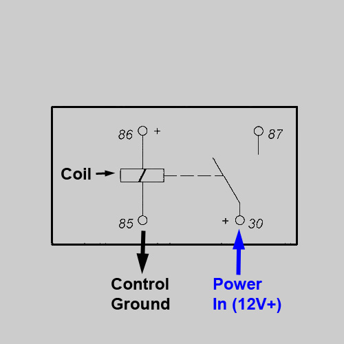 |
Schematic of SPST relay in de-energized (i.e. off) position. No current flows through the coil, the spring holds the moveable contact open, no current available at terminal 87. Essentially it's just a fancy electrical switch in the OFF position.
|
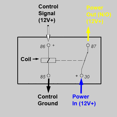 |
Schematic of SPST relay in energized (i.e. on) position. Current flows through the coil from terminal 86 to 85, the resulting magnetic field holds the moveable contact closed, terminals 30 and 87 are connected, high current available at terminal 87. Essentially it's just a fancy electrical switch in the ON position. |
For this project we only need a SPST relay, but I happened to use a SPDT because they;re more common and that's what I had lying around the shop. Either will work - just don't connect anything to terminal 87a if you use a SPDT relay as I did. Relay Specifications:There are two specifications that you must consider when selecting a relay for use on your ATV: the coil voltage and the current carrying capability of the contacts (i.e. the amp rating of the relay). The coil voltage required is 12 volts DC. The current carrying capability (rating) of the relay is how much current can be passed through the contacts without damage to the contacts. 30amp and 40amp ratings are common. Some SPDT relays will have different current ratings for the NC contacts (which are held together by spring tension) and the NO contacts (which are held together by the electromagnet). If so you may see the rating listed as 30/40A. In this case, the first (and almost always lower) number will be for the normally closed contacts (terminal 87a), and the second, larger rating will be for the normally open contacts (terminal 87). Make sure you choose a relay with a rating sufficient to carry all the current you will pass through it. In my case I chose a 40amp relay and so the combined power draw of all accessories wired to my mini fuse panel cannot exceed 40 amps. Relay SocketIn order to wire in a relay, you use a relay socket. |
|
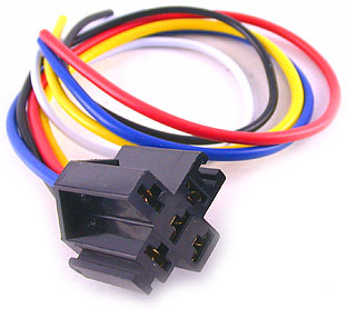 |
They are available pre-wired with female terminals and a multicoloured pigtail, like this one. The drawback to this style is that you are limited to the wire size use, which is normally a max of 14 gauge. Incidentally, the wire colours match a common standard (same colours indicated in the schematics above). |
The standard colours are:
|
|
|
Alternatively you can use a bare socket, like the one pictured here that I used... |
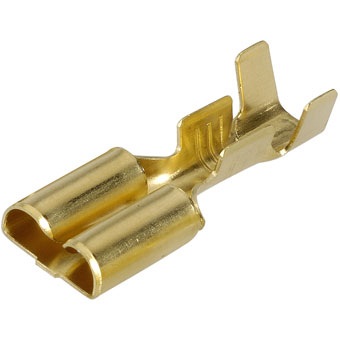 |
...and crimp on the required female terminals, like this one, using the wire gauge of your choice. So let's move on to the installation and see how that is done. |
Installation
|
|
 |
The battery and main wiring on the Grizzly 700 are located under this front panel that Yamaha call the "lid", but which I call the hood. |
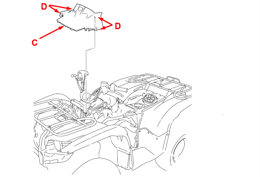 |
To remove the hood (C), you pull up and forward on the panel the four pins (D) disengage from their grommets. |
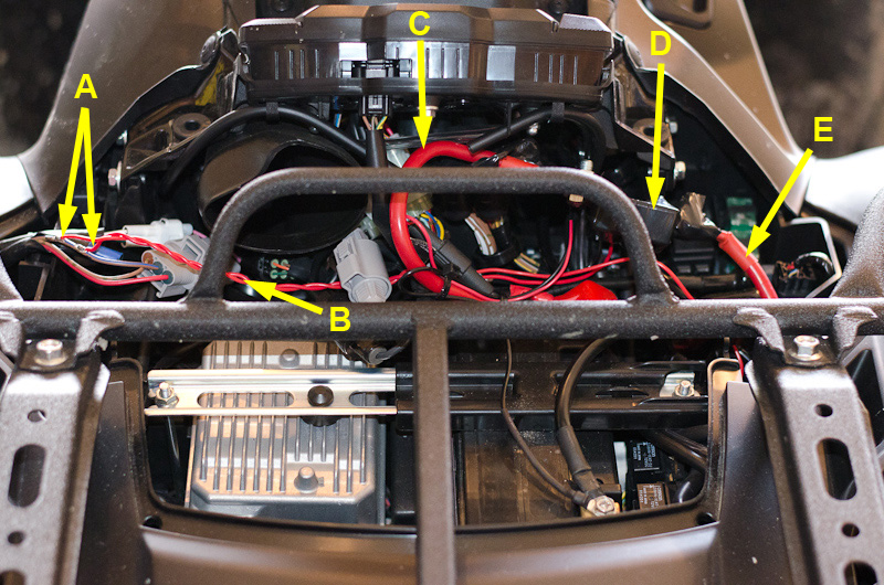 |
My Grizzly was delivered with a winch installed by the dealership, so here you can see: A - Location where the dealership spliced into the stock 12V+ wire (brown with blue stripe) that is hot when the key is turned on. B - The two red wires spliced into the brown/blue wire that carry power to the handlebar winch control and the fender-mounted remote winch control socket. C - Winch power wire - connects battery (+) terminal to winch circuit breakers D - Winch circuit breakers E - Winch power wire that connects the circuit breakers to the winch motor. |
 |
Before beginning any work, the first step is to disconnect the battery negative cable. |
 |
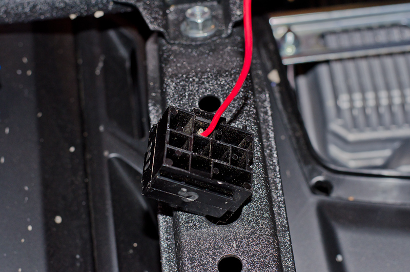
There are two wire bundles that enter the area under the hood from the right front fender. One has two wires and a white connector - it is the wiring for the factory 12V+ accessory socket mounted on the fender. The other has three wires and a larger grey connector. The wires are red, brown with green stripes, and brown with blue stripe. It is this last one, brown with blue stripe, that we are going to tap into to provide the control voltage to the relay (terminal 86). |
 |
As I mentioned, the dealership had already tapped into this wire when installing my winch. If you don't have such an arrangement, you can just carefully strip a little of the insulation off one side of the brown/blue wire to provide a solder connection for the relay control wire. I wasn't thrilled with the way the dealership had spliced directly into this wire for the winch controls and left then un-fused, so I decided I would remove these two connections and instead connect the two red winch-control wires to my fuse panel once installed. |
 |
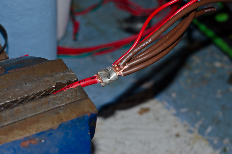
So I desoldered the winch control wires, covered one of the insulation gaps with liquid electrical tape (A), and then soldered on a new 16 gauge red control wire (B) that will turn the new relay on and off. This wire will only carry less than an amp (it takes well less than an amp to activate the relay), and will be fairly short as well, so virtually any gauge wire 22 or above will do. |
 |
Liquid electrical tape used to cover spliced connections. |
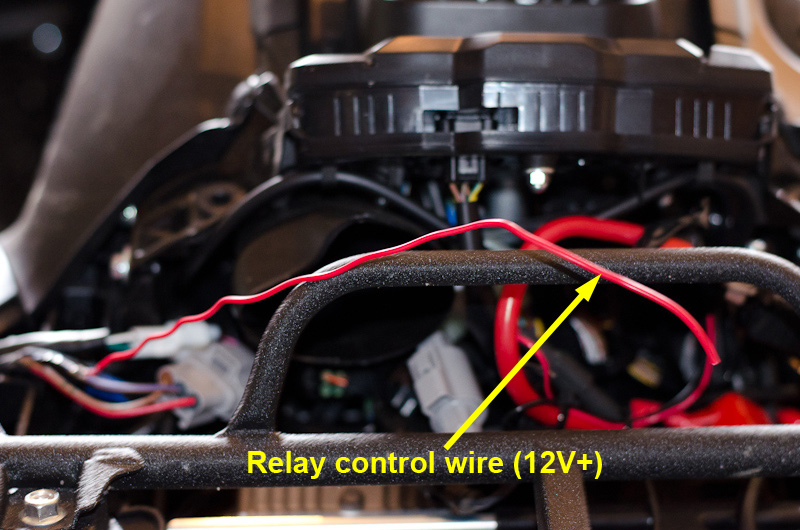 |
So now I have my first relay wire - the control power wire that will connect to terminal 86. |
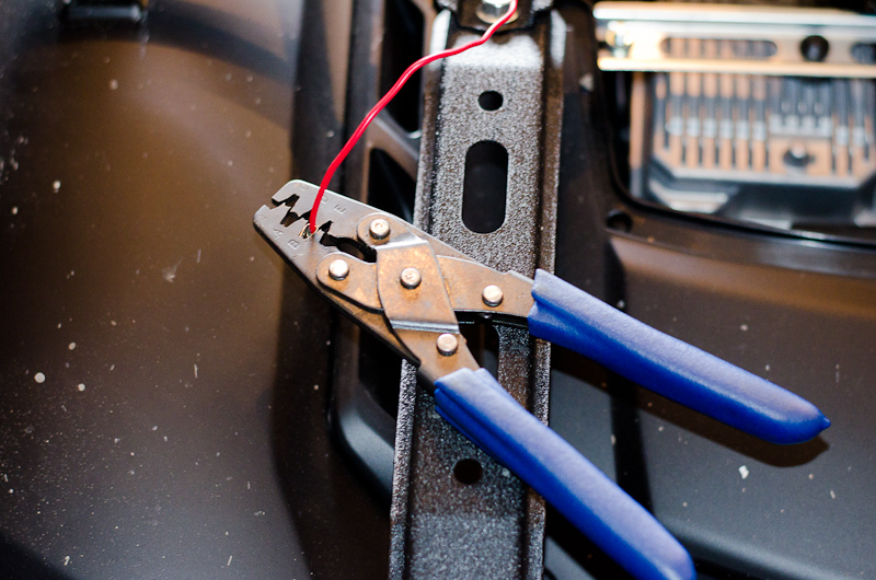 |
On the end of this wire I crimped a female spade terminal... |
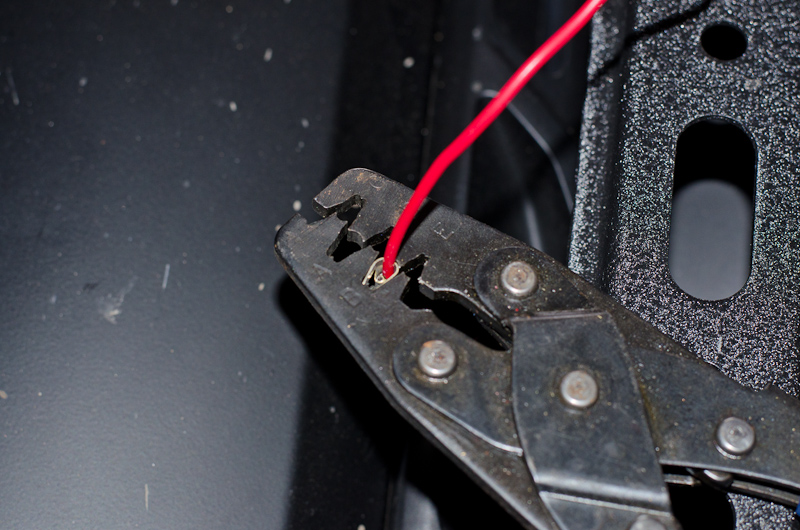 |
...using a tool known as a barrel crimper. You can get these fairly cheaply at auto parts stores, tool specialty shops, and online. However, if this is the only relay you will ever install, you can crimp on the terminals with patient and careful use of small needle-nose pliers, possibly backed up with a dab of solder. |
 |
Once the terminal is crimped on, you insert it into the back of the relay socket and it clicks in place. The terminals have a little tab that prevents them from being pulled back out. Make sure you insert the terminal into the correct numbered slot in the relay socket! I then did the same for the connections to terminal 85 and terminal 30. The other end of the wire connected to terminal 85 was then connected to the battery hold-down stud with a ring terminal to provide the relay ground.
|
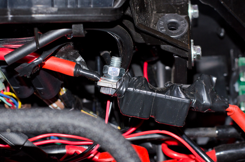 |
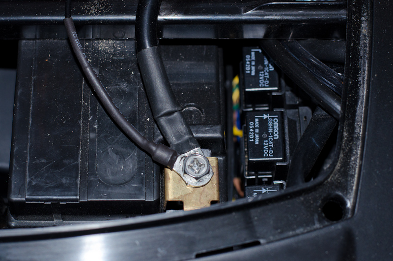
The other end of the wire connected to terminal 30 was then connected to the winch circuit breaker bolt with a ring terminal to provide the relay high-current power. I used 8 gauge wire for this connection. |
 |
|
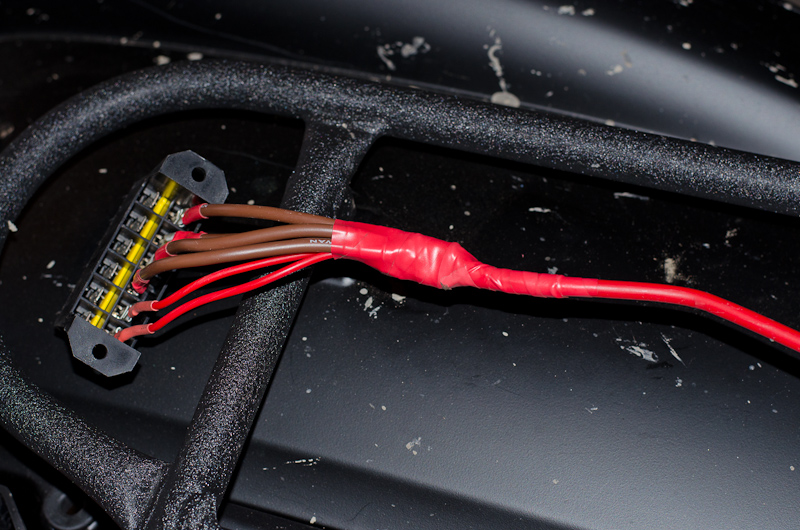 |
For the final relay connection, terminal 87, I crimped a relay terminal to another piece of 8 gauge wire and inserted this in the relay socket. Then, on the other end of this 8 gauge wire, I spliced six individual wires and connected each to one of the connections on the fuse panel using a female spade connector. |
|
All relay connections complete. |
 |
|
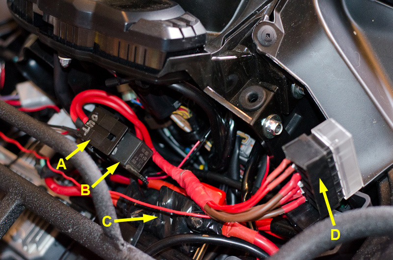 |
Relay switched mini fuse panel all wired up. A - Relay socket B - 40 amp relay C - Winch circuit breakers D - 6-slot mini fuse panel |
|
The last step was to wire the two winch control wires I originally removed from the brown/blue wire into one of the slots in the fuse panel and add a small 5 amp fuse. |
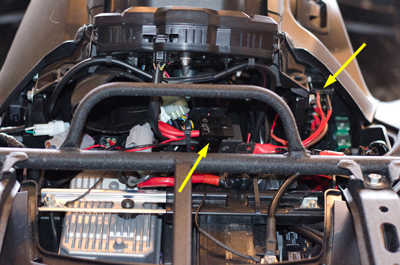 |
Here are the installed positions of the new components. The relay is zip tied down to the existing winch wiring. The new fuse panel fits neatly up under the left side panel. |
 |
And the hood snaps right back in place! Now I have a 6-slot mini fuse panel ready to accept all my electrical accessories as I add them, all controlled by the main key switch through the relay. |
|