|
Can-Am Accessory Fuse Box By Bill "BillaVista" Ansell |
IntroductionOne of the most fun parts of ATV ownership is modifying it to your own personal needs and tastes - taking something stock and making it your own. Many of the most useful and popular accessories are electronic. I myself have big plans - heated grips, GPS, extra lights, radio, phone charger- the list is long. However, many ATVs, including the Outlander, don't come from the factory optimized for adding aftermarket electronics. And cobbling them on one at a time can lead to a spaghetti mess of spliced and tapped wires that can be a mess at best and at worst lead to poor performance of your electronics or even unsafe wiring. |
 |
That's why one of my first mods was to add a small auxiliary fuse box, powered through a 40 amp relay that is activated by the main ignition switch. Now I have a tidy little system that tucks neatly under the seat. It has four available accessory slots, each individually fused, uses standard automotive ATC-type fuses, and the whole thing powers up or down with the key (main switch) so that there's no fear of accidentally draining the battery by unintentionally leaving accessories on. The text and pictures here are supplemental to the video article I made of this project, which appears at the end of this article. If you want to skip right to watching the video first (recommended), click here. Overview |
|
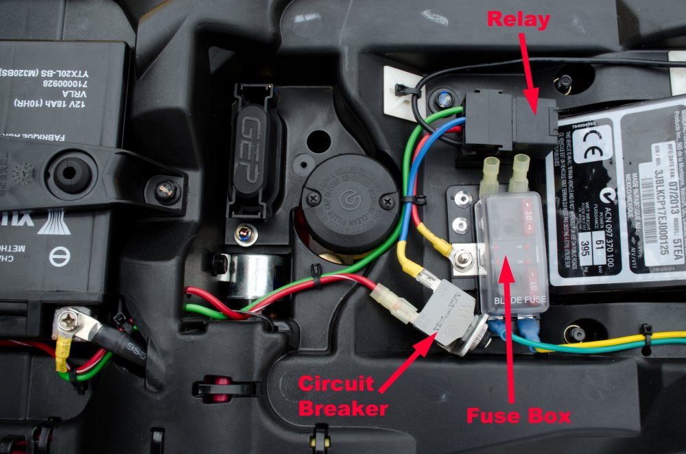 |
This is a shot of the finished product. The main components are a circuit breaker to protect the main 12V supply wire, a relay to power the accessory fuse box only when the key is turned on, and the 4-slot fuse box. The relay and fuse box are riveted to the black plastic "battery tray" under the seat. The small aluminum bracket the holds the circuit breaker uses the existing factory bolt that holds down the battery tray. |
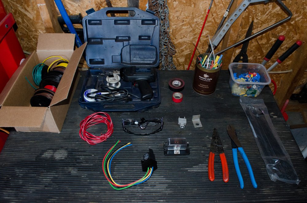 |
Most of the stuff I used in the project. Clockwise from top left:
|
Fuse Panel |
|
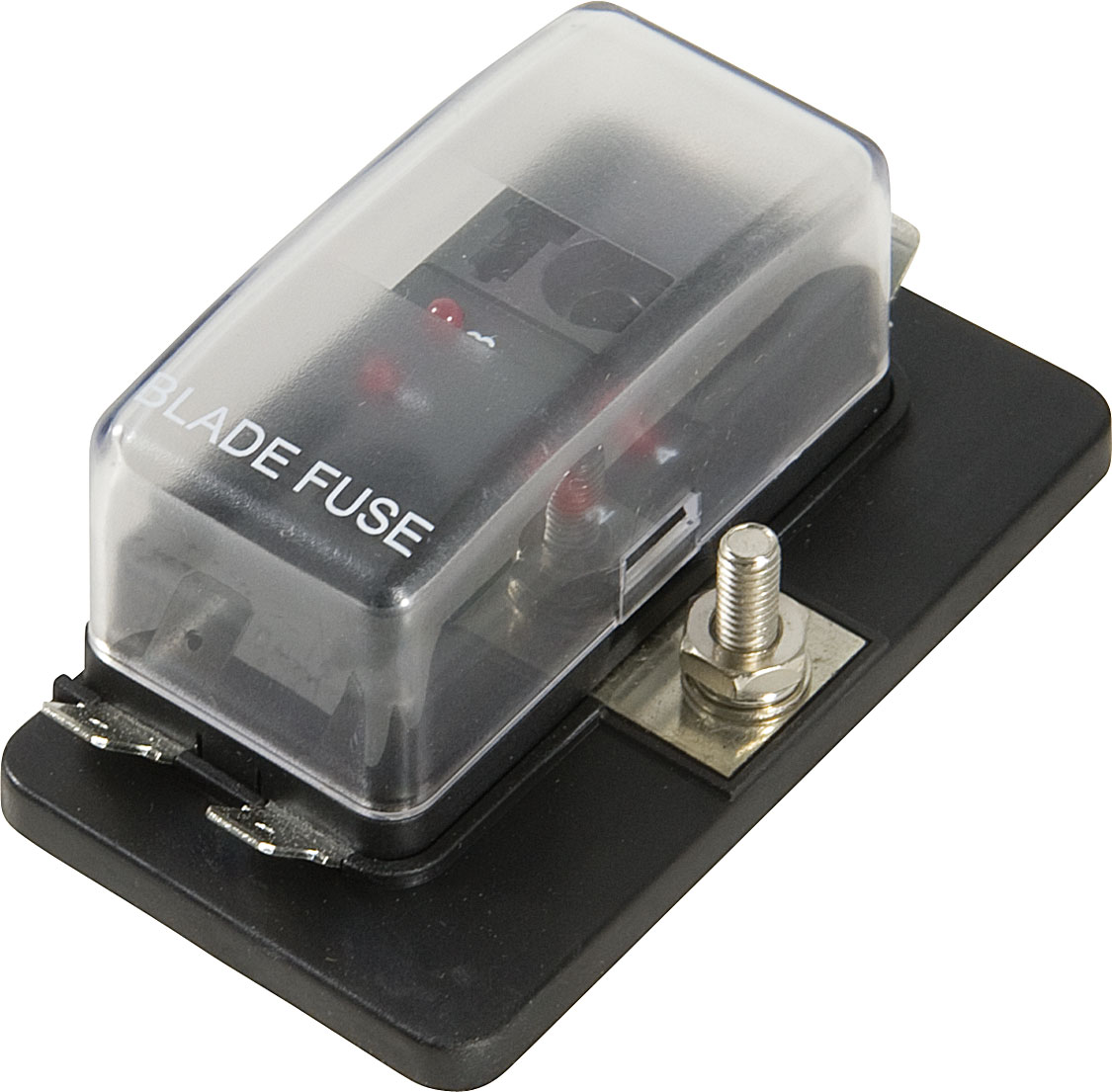 |
This is the fuse panel that I used. It has standard male blade terminals for each of its fused circuits (4 total). I bought it from Princess Auto, the sku is: 8479479. It was < $10 on sale and measures 6.5 x 3.8 x 1.5 in. The listing on their website is here. |
 |
These are the ATC-style automotive blade-type fuses that it uses. |
Installation
|
|
 |
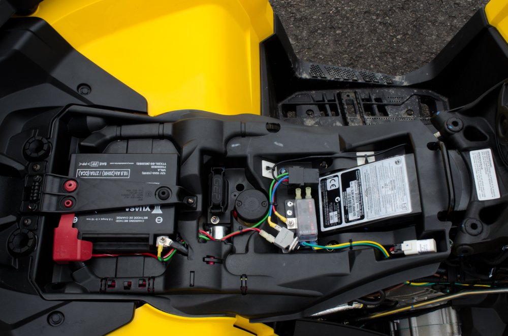
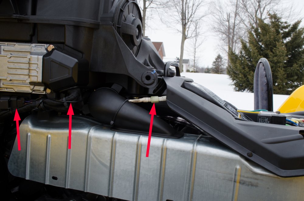
This is the area beneath the seat where most of the parts are installed. It was formerly occupied by the little Can-Am toolkit. |
|
This is an overview of the finished installation so you can see what we're aiming for. |
|
Close-up. |
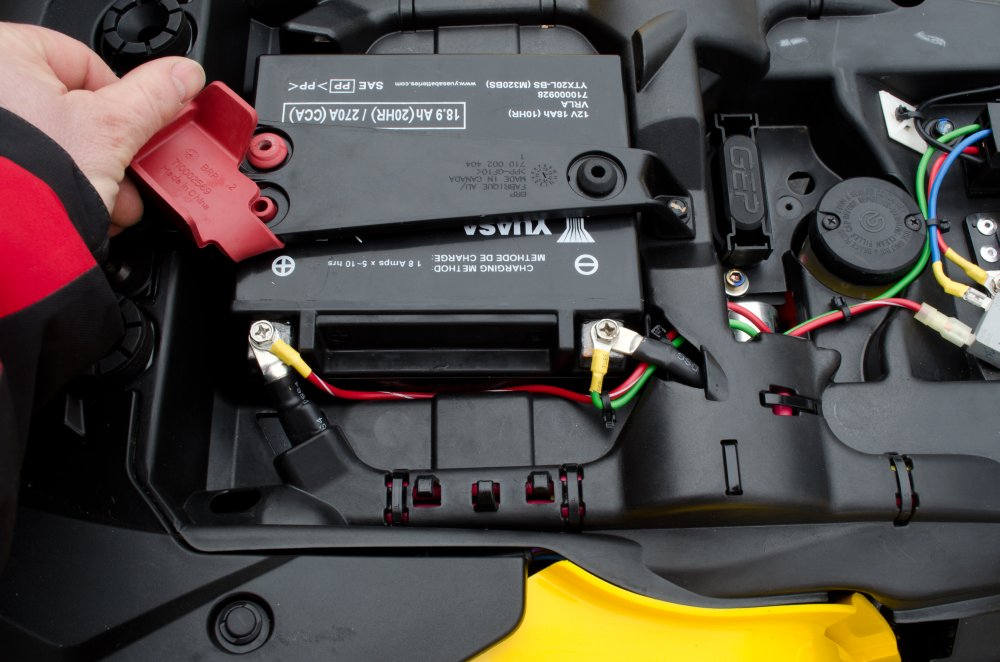 |
The main 12V supply for the fuse panel (through the circuit breaker) is wired directly to the battery (+) terminal. The Relay is also grounded directly to the battery (-) terminal. |
 |
I drilled two small holes to run the wires through. |
 |
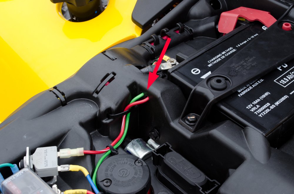
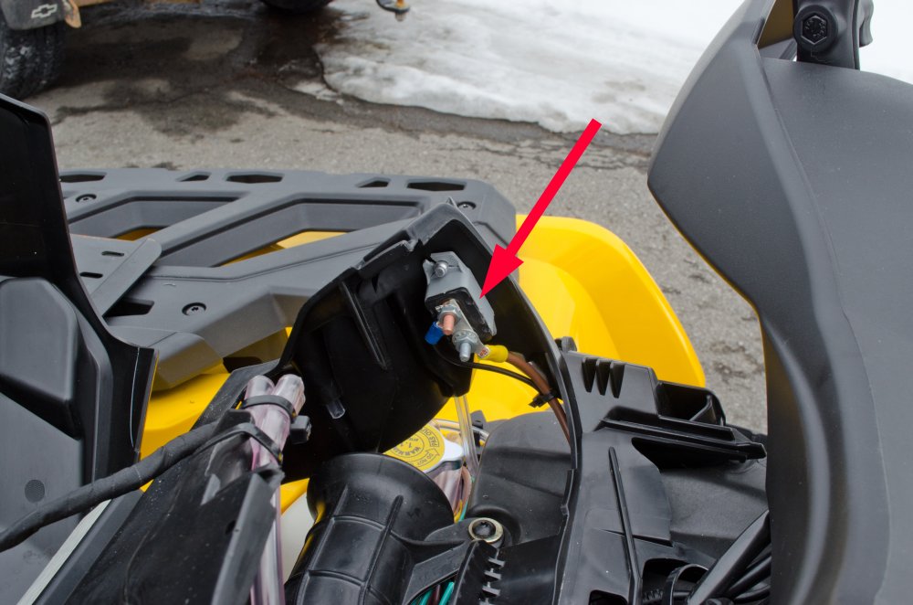
In order to turn the relay on and power the fuse box, a 12 volt "signal" is required. I wanted the relay to come on with the key so I chose to tap into the factory 12 volt accessory socket wire that is powered by the key. |
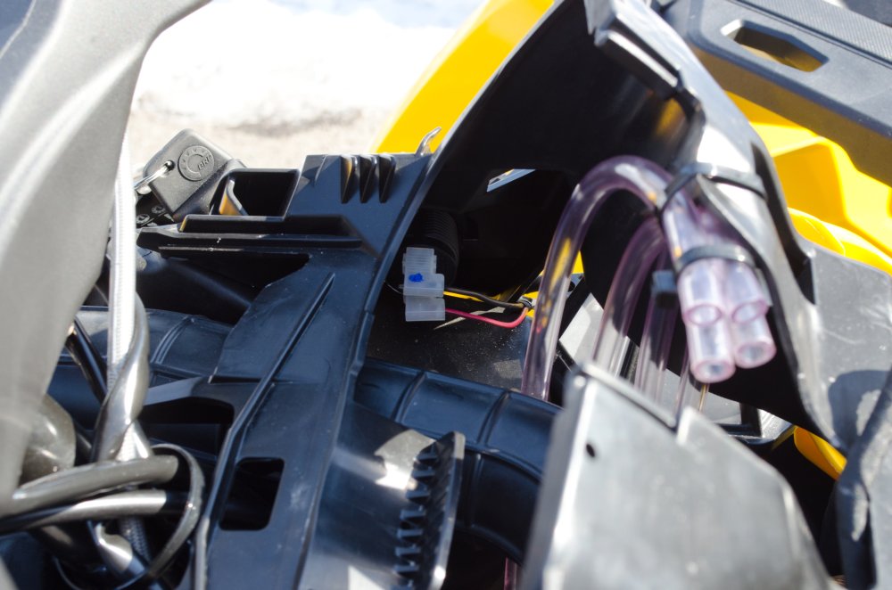 |
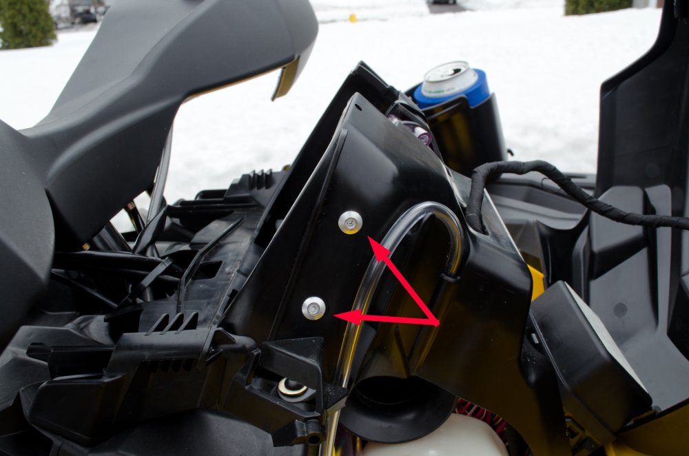
The power wire for the factory 12 volt accessory socket is the lower red wire. |
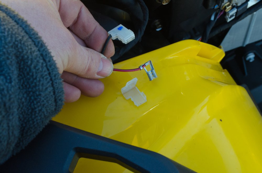 |
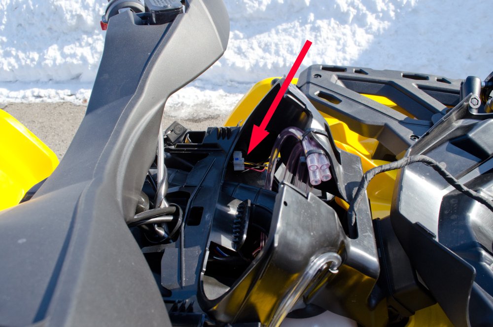
After disconnecting the wire from the socket, the little plastic cover unclips revealing a 90* female spade terminal (these are called "flag" terminals). |
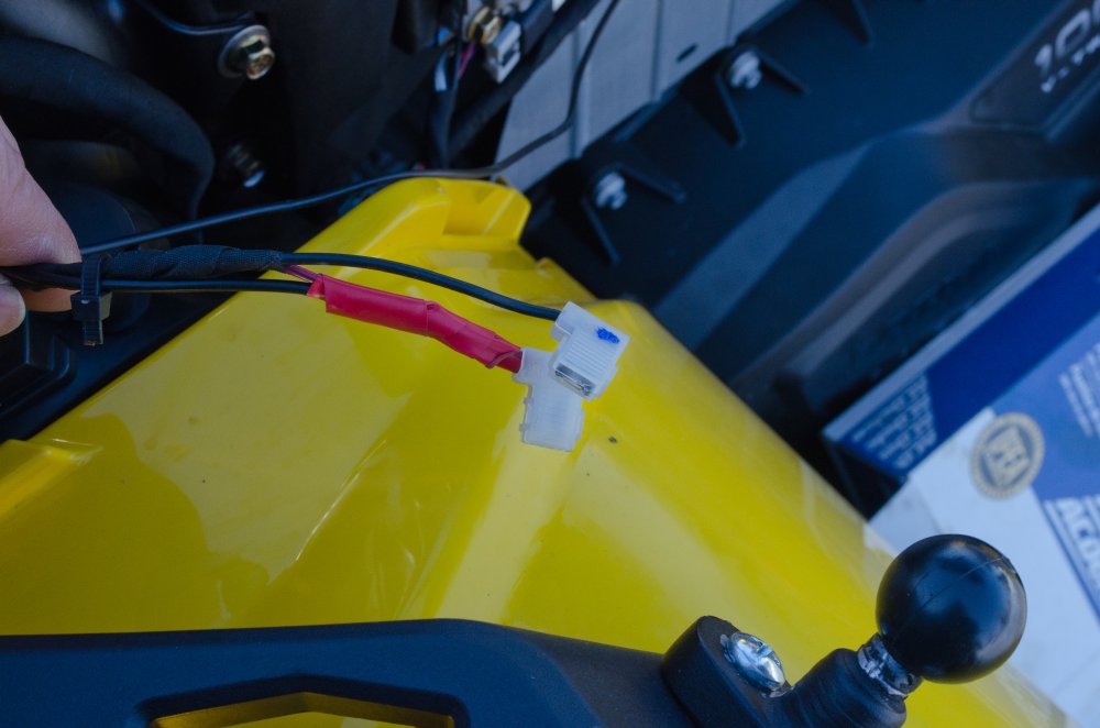 |
I clipped the original terminal off, twisted the original wire together with a new 18-gauge wire for the relay signal, crimped on a new flag terminal, and then re-installed the little plastic cover. The tape job looks very poor because it was -26*C when I did this and electrical tape does NOT want to stick well at that temperature. |
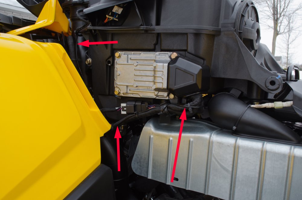 |
The new signal relay wire I ran alongside the existing wiring harness and secured it with zip ties. |
 |
I installed a male/female spade connector in the wire to ease removal / installation of parts if required. |
 |
I drilled a small hole in the plastic battery tray to run the wire through and to the relay. A couple of small stick-on clips with zip-ties are used to keep the wire neat and secure. |
 |
While I was running wires, I ran two from the fuse box up front to the pod. One powers my GPS and the other is just a spare ready for whatever my next electrical accessory is. |
 |
Since most electrical accessories will require power and ground up near the handlebars, while I was at it I decided to add a small ground block under the pod. This will allow me to easily access ground for my GPS and any future accessories. |
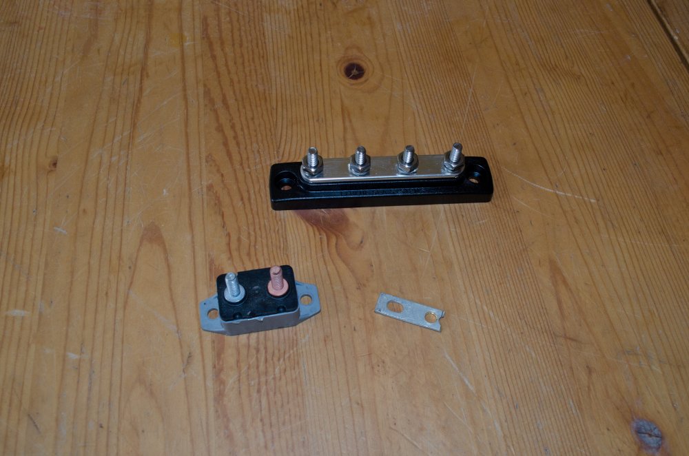 |
I didn't have a small enough bus-bar, so I decided to convert a small circuit breaker into one. The bus-bar in the top of the picture is a 100-amp marine unit, but it was both a little too large as well as being overkill for my needs at 100 amp capacity. |
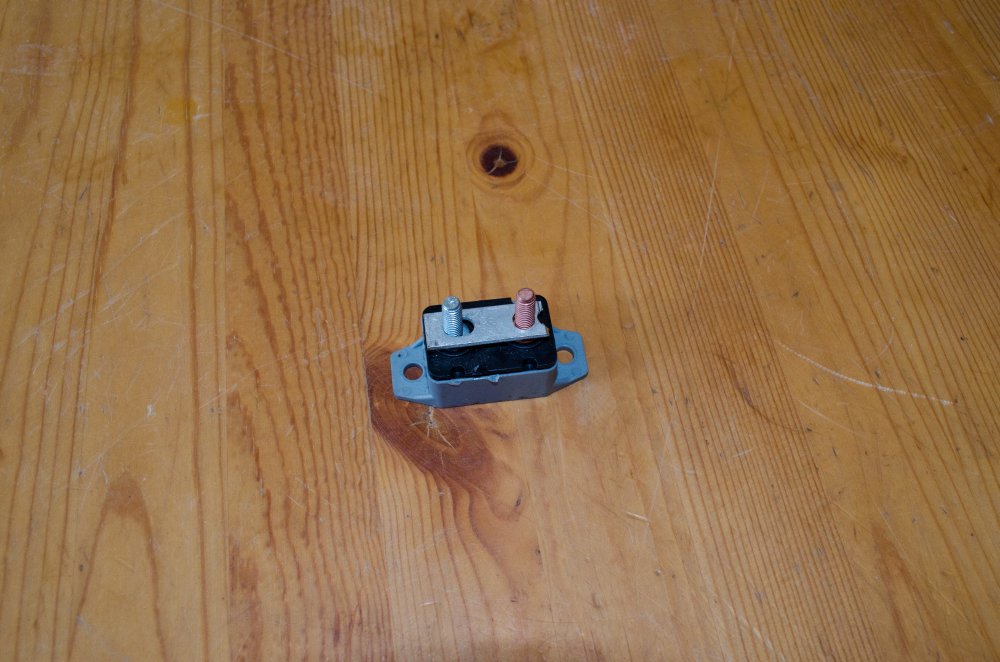 |
So I cut a small aluminum strip to permanently connect the two posts of the circuit breaker and turn it into a small bus bar. |
 |
This "bus bar" I riveted to the pod support so now I have easy access to ground connections up under the pod. |
 |
The ground for my mini bus-bar is supplied by a 10-gauge wire I connected with a bolt and ring terminal to the factory grounding plate on the frame. |
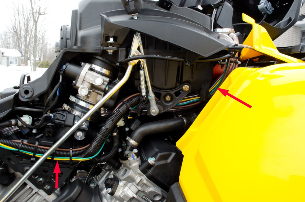 |
This ground wire as well as the two new power wires were again run alongside the factory wiring harness up to the pod, and secured with zip ties. |
 |
The green wire is just tucked down for future use... |
 |
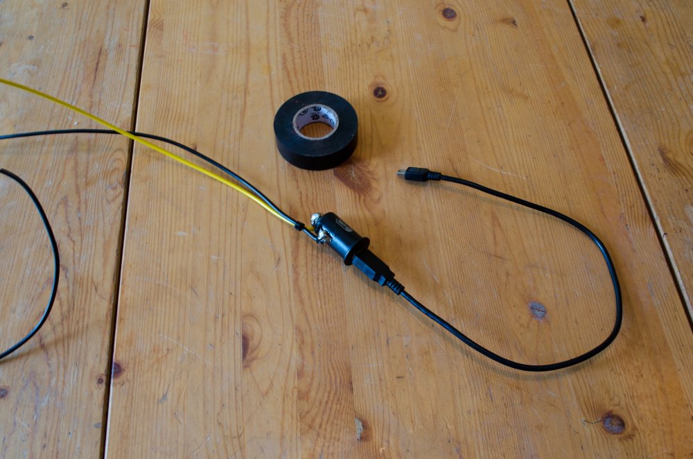
...but I had to make one more component to be able to power my GPS with the yellow wire. Since my GPS power input is a 5V mini-USB input, I needed to covert the 12V at the yellow wire into 5V USB input. |
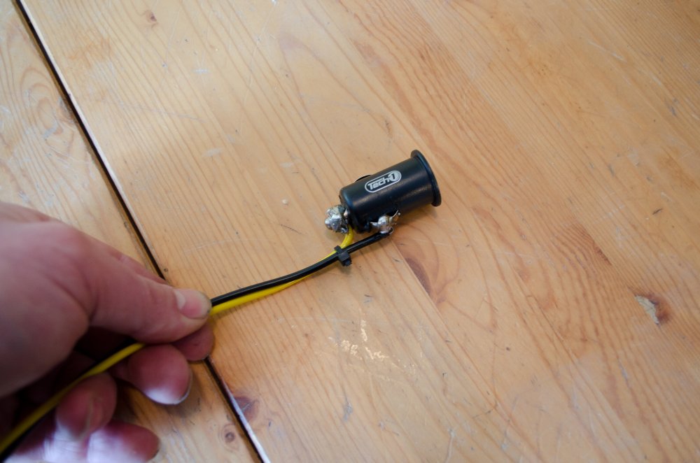 |
My solution was to take a small 12V to USB converter I bought at the dollar store (intended to be inserted in a cigarette-lighter socket) and solder the yellow 12V power wire to it as well as a ground wire. |
 |
Giving me a 5V USB power port. |
 |
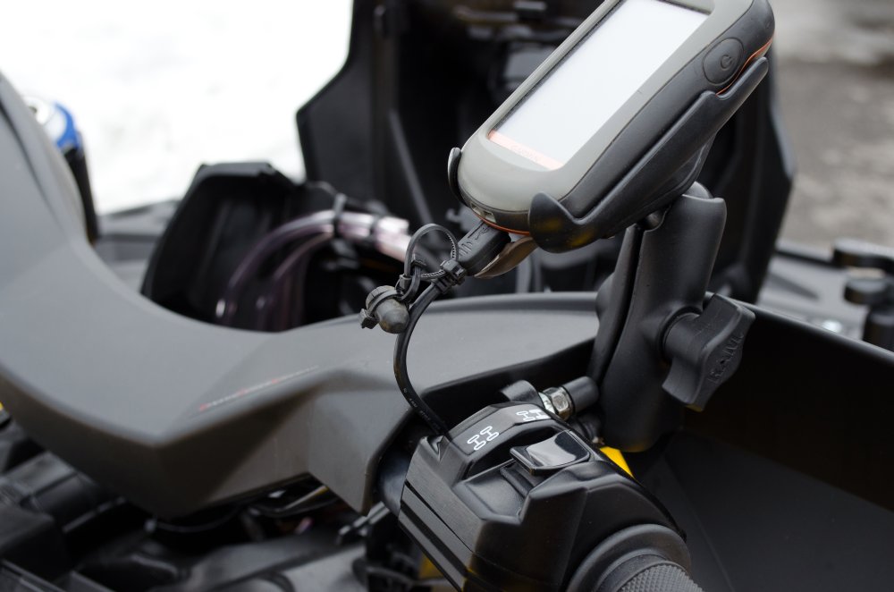
My GPS power cable now plugs into the USB socket... |
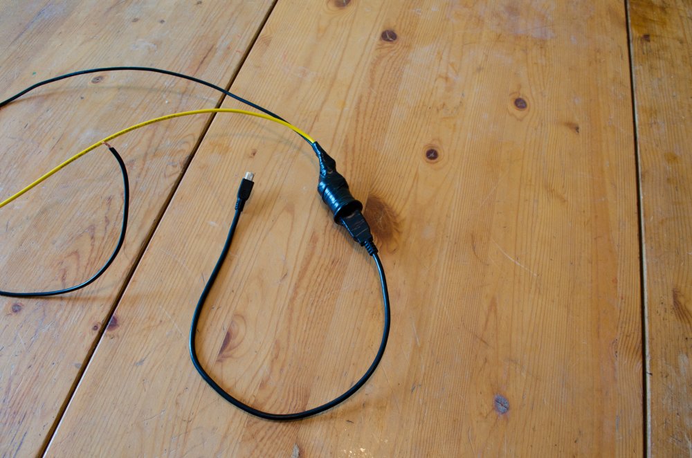 |
... and I taped the whole thing up and installed it under the pod. The ground wire I connected to my new ground mini bus-bar. |
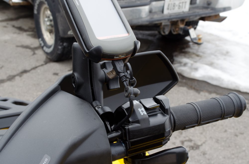 |
Everything tucks up neat under the factory panels and the result is neat GPS power right at the handlebars where I need it. |
Relay - Technical DetailsA relay is a remote-controlled electrical switch. It allows a low current control circuit to control (turn on and off) a second high current circuit. Using a relay can therefore allow you to isolate the the high power (current) demand of some accessories from the switch that is used to turn the accessory on or off. This means the the actual switch that controls the accessory needs only to carry a fraction of the current that the accessory itself requires. As such, smaller, more ergonomic, and cheaper switches can be used to control even the highest power accessories. If it weren't for relays, high power accessories would have to be controlled by very large, heavy, and expensive switches capable of handling 40, 50, or even 100 amps. Other advantages to using a relay include:
How it worksInside a relay is a small electromagnetic coil. When a small control current is passed through the coil a magnetic field is created. This magnetic field pulls a set of contacts together and thus the high current now flows through these closed contacts and to the device being powered. When the control current is removed the magnetic field collapses and a small spring applies force and holds the main contacts open until the control switch is switched on again and control current once again flows through the coil. A relay can be controlled with an electrical current as small as 150 milliamps (at 12 volts DC). Depending on the rating of the relay, the device being powered through the relay (the switched output of the relay) can be as high as 30, 40, or even 75 amps. |
|
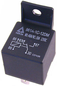 |
This is a typical automotive style relay. This one with a built-in mounting tab. The circuit schematic is printed on the top, which we shall look at momentarily. Not also that the specification (current carrying capacity) is also printed on it. This is where it says: NO: 40A / NC: 30A 12VDC This means that its capacity is 40 amps through the "normally open (NO)" circuit, and 30 amps through the "normally closed (NC)" circuit, both ratings at 12 volts direct current (12VDC) - which is the voltage your car and ATV work on. We;; look at what the "normally open (NO)" circuit and the "normally closed (NC)" circuit are shortly. |
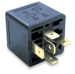 |
Another view of the typical 40A automotive relay, showing the terminals to which the wiring is attached. Note that this one also has the circuit diagram stamped on it - this time on the side. This style of relay is also commonly known as a "Bosch Relay", so named after the company that popularized its use. If you look carefully at the bottom, beside the blade terminals, you will see small numbers stamped next to each terminal. This is then umber of the terminal, and each number corresponds to a number on the circuit diagram. |
Note that both of these relays have five terminals, and therefore also five numbers in the schematic. This type of relay is known as a single-pole double-throw (SPDT) relay - it has both a normally-open contact and a normally-closed contact in the main high-current circuit. Let's just explain that terminology as it is quite useful to understand. Switch TerminologyFor all switches, whether they are simple mechanical switches (like a light switch in your house) or an electromechanical switch like a relay, the number of 'poles' indicates how many electrical circuits are controlled by the switch. The number of 'throws' indicates the number of positions of the switch that result in an electrical connection. Note that this means that, depending on the switch design, the number of throws can be either:
The following simple switch diagrams should help clarify this: |
|
 |
This is the schematic diagram for a single pole, single throw (SPST) switch, This is the simplest kind of switch. An example would be a simple on-off switch. It controls a single circuit (so "single pole") and there is only one switch position that results in a circuit connection - the "on" position (so "single throw"). Of course, this switch has two control positions: "on" and "off", so the number of throws is one less than the number of control positions In the diagram at left, the switch is seen in the "off" or "open" position - i.e. there is no circuit completed. |
 |
This is an example of an actual SPST switch. It is single pole - so It controls a single circuit (turns something ON or OFF) It has a single throw - so there is only one switch position (ON) that results in a completed electrical circuit. It has two control positions - ON and OFF |
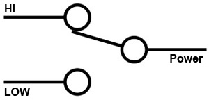 |
This is the schematic diagram for a single pole, double throw (SPDT) switch, This is also a simple and very common kind of switch. An example would be a selector switch where the user selects between two positions - a light switch with "HI" or "LOW" positions is an example. It controls a single circuit (so "single pole") and there are two switch position that can results in a circuit connection - the "HI" position or the "LOW" position - so "double throw"). This switch could have two or three control positions: It could be just "HI" and "LOW" and therefore always be in one or the other, or it could also have an intermediate "off" position, so depending on the actual switch design the number of throws could be either be the same as the number of control positions (in the case of "HI" or "LOW") or one less than the number of control positions (in the case of "HI" "OFF" "LOW") In the diagram at left, the switch is seen in the "HI" position. |
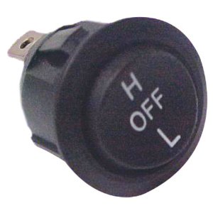 |
This is an example of an actual SPDT switch. It is single pole - so it controls a single circuit (turns something to HI, OFF, or LOW) It is double throw - there are two positions (H and L) that result in a completed electrical circuit. It has three control positions - H, OFF, and L |
Back to Relays |
|
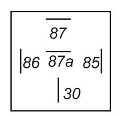 |
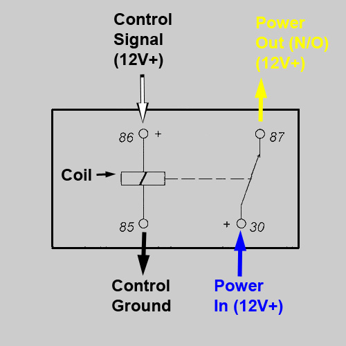
This is a schematic diagram of the five blade terminals on an SPDT relay. They are always in this orientation and always the same, regardless of the brand or rating - making them interchangeable. The terminals are as follows:
|
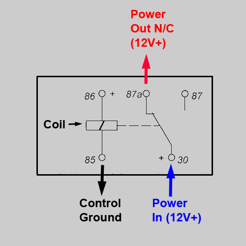 |
This is a schematic of an SPDT relay. The electromagnetic coil is illustrated in the middle. When there is no voltage across terminals 85 and 86, no current flows through the coil, therefore no magnetic field is produced, and the relay's movable contact (connected to terminal 30) is held, by spring tension, against the electrical contact which is connected to terminal 87a (the normally closed contact). In other words, when no voltage is applied to the relay coil, terminal 30 is connected to terminal 87a, and therefore high current 12V DC is available at terminal 87a, as shown in this schematic
|
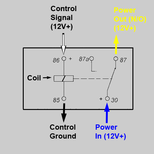 |
When 12 volts is applied to the relay coil (terminals 85 and 86), current flows through the coil, a magnetic field is created and thus the movable contact (connected to terminal 30) is pulled by the magnetic field into contact with the electrical contact which is connected to terminal 87. In other words, when voltage is applied to the relay coil, terminal 30 is connected to terminal 87, and therefore high current 12V DC is available at terminal 87, as shown in this schematic. |
So, in practical terms, what we do is wire terminal 86 to some source of switched 12V DC - that is, power that comes from either a small dash switch or even from the main key switch. Let's assume the key switch for this example. We connect terminal 85 to ground. We connect terminal 30 to a fused source of high current - say a nice fat 8 or 10 gauge wire from the battery or main distribution block. Now, when the key is off, terminal 87a will have high current 12V DC, and when we turn the key on, the relay switches, and high current 12V DC is available at terminal 87. So we can wire terminal 87 to a single high-current accessory, or in my case, to a small fuse panel, and now when we turn the key on our fuse panel is powered, and when we turn the key off power is removed from the fuse panel and any accessory wired to the fuse panel. It's not terribly common to wire anything to terminal 87a - the "normally closed" terminal, as anything so wired would be "on" when the key is off, and "off" when the key is on. Perhaps one example would be a small alarm warning light that you want to come on only when the key is off. But like I said, normally-closed connections are rare. So much so, in fact, that you can get relays without them. That is, instead of a SPDT relay, you can get an SPST relay! |
|
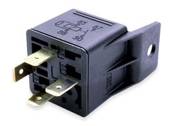 |
This is a 4-terminal SPST relay. It's the same as the SDT, except that there is no terminal 87a, so no contact where 12V DC is available when the relay is not energized (i.e. when the relay isn't getting current to terminal 86) Note the schematic is still stamped on the side, and that the terminal pin-out is exactly the same as the SPDT relay already shown except terminal 87a (the centre one) is missing . |
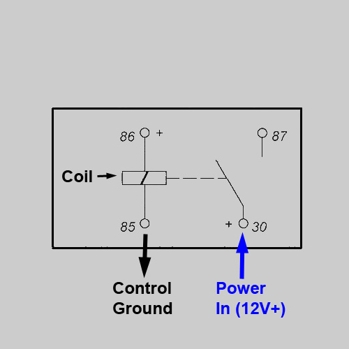 |
Schematic of SPST relay in de-energized (i.e. off) position. No current flows through the coil, the spring holds the moveable contact open, no current available at terminal 87. Essentially it's just a fancy electrical switch in the OFF position.
|
 |
Schematic of SPST relay in energized (i.e. on) position. Current flows through the coil from terminal 86 to 85, the resulting magnetic field holds the moveable contact closed, terminals 30 and 87 are connected, high current available at terminal 87. Essentially it's just a fancy electrical switch in the ON position. |
For this project we only need a SPST relay, but I happened to use a SPDT because they're more common and that's what I had. Either will work - just don't connect anything to terminal 87a if you use a SPDT relay as I did. Relay Specifications:There are two specifications that you must consider when selecting a relay for use on your ATV: the coil voltage and the current carrying capability of the contacts (i.e. the amp rating of the relay). The coil voltage required is 12 volts DC. The current carrying capability (rating) of the relay is how much current can be passed through the contacts without damage to the contacts. 30amp and 40amp ratings are common. Some SPDT relays will have different current ratings for the NC contacts (which are held together by spring tension) and the NO contacts (which are held together by the electromagnet). If so you may see the rating listed as 30/40A. In this case, the first (and almost always lower) number will be for the normally closed contacts (terminal 87a), and the second, larger rating will be for the normally open contacts (terminal 87). Make sure you choose a relay with a rating sufficient to carry all the current you will pass through it. In my case I chose a 40amp relay and so the combined power draw of all accessories wired to my mini fuse panel cannot exceed 40 amps. Relay SocketIn order to wire in a relay, you use a relay socket. |
|
 |
They are available pre-wired with female terminals and a multicoloured pigtail, like this one. Incidentally, the wire colours SHOULD match a common standard (same colours indicated in the schematics above), but they do not always. |
The standard colours are:
|
|
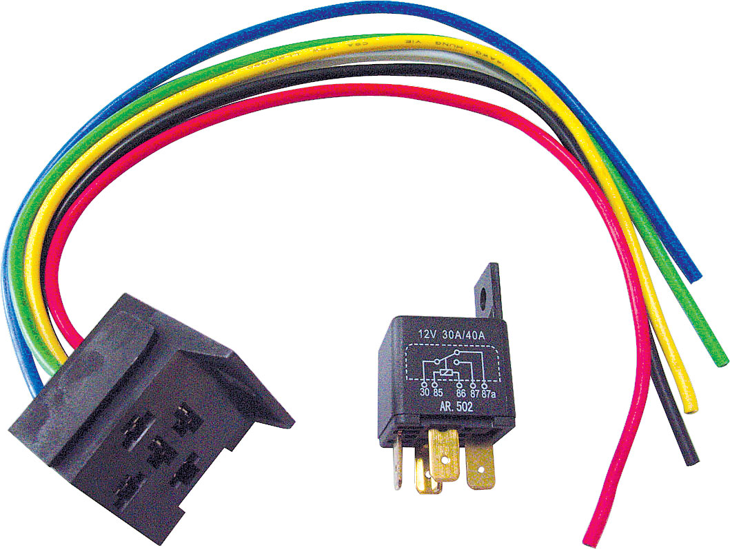 |
However, the Princess Auto relay I used has non-standard wiring colours, as follows"
All very confusing! But not that big a deal if you check the terminal numbers carefully before wiring it up. The Princess Auto sku for the relay is 8402042. Link to the item is here. |
Can-Am Accessory Fuse Box Video
|
|
|